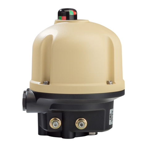
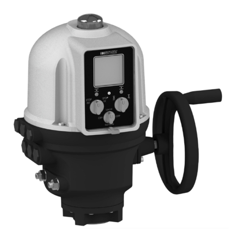
Bernard Controls SD Series Instructions for use

instructions de mise en service,
stockage et entretien
instructions for start-up,
storage and maintenance
anleitung für die inbetriebnahme,
lagerung und wartung
modèles / models / modelle :
oa, oap, as, asp, bs, sra, src, asm
TMS300_SD_revE_A/F/D
SD
Gamme
Range
Reihe

AS100/AS200/AS400
SRA/SRC/ASM
3
1 Sécurité Page 3
2 Montage Page 3
3 Commande manuelle et débrayage Page 3
4 Raccordement et test électriques Page 4
5 Réglage des butées mécaniques et des contacts de fin de course Page 5
6 Réglage du limiteur de couple Page 6
7 Potentiomètre de recopie de position (option) Page 6
8 Transmetteur de position type TAM (option) Page 7
9 Entretien et stockage des servomoteurs Page 8
Accessoires de la gamme SD Page 24
Autres gammes de produits Page 24
Schémas de câblage interne Page 25
Exemples de circuits de puissance Page 26
Exemples de réalisation de coffrets de commande Page 27
SOMMAIRE
1 Safety information Page 10
2 Assembly Page 10
3 Handwheel operation and declutching Page 10
4 Electrical connections and preliminary tests Page 11
5 Setting of mechanical stops and travel limit switches Page 12
6 Setting of torque limit switches Page 13
7 Position feedback potentiometer (option) Page 13
8 TAM position transmitter (option) Page 14
9 Maintenance and storage instructions Page 15
SD range accessories Page 24
Other products ranges Page 24
Internal wiring diagrams Page 25
Examples of power supply circuits Page 26
Control panel design examples Page 27
TABLE OF CONTENTS
1 Sicherheitsinformationen Seite 17
2 Montage Seite 17
3Handradbetätigung und Auskuppeln Seite 17
4 Elektrische Anschlüsse und Prüfungen im Vorfeld Seite 18
5 Einstellung der mechanischen Anschläge undWegbegrenzungsschalter Seite 19
6 Einstellung der Drehmomentbegrenzungsschalter Seite 20
7 Potentiometer für Positionsmeldung (option) Seite 20
8 TAM-Positionsmelder (option) Seite 21
9 Wartungsanleitung und Hinweise zur Lagerung Seite 22
Zubehör für die SD-Riehe Seite 24
Weitere Produktreihen Seite 24
Interne Stromlaufpläne Seite 25
Beispiele für Stromversorgungskreise Seite 26
Beispiele für Schalttafelausführungen Seite 27
INHALTSVERZEICHNIS
1 sécurité
Cet appareil répond aux normes de sécurité en vigueur. Toutefois, seule
une installation, une maintenance et une utilisation effectuées par
un personnel qualifié et formé permettront d’assurer un niveau de sécurité
adéquat.
Avant montage et démarrage, lire attentivement l’ensemble de ce document.
2 Montage
Le servomoteur doit être boulonné sur l’appareil à motoriser.
Les servomoteurs BERNARD peuvent fonctionner dans n’importe quelle
position. Cependant, les presse-étoupes ne devraient par être orientés
vers le haut (étanchéité) et le moteur de préférence pas placé en position
basse (condensation d’eau interne potentielle).
Note 1 : ne pas transporter les servomoteurs par le volant sous peine
d’endommager le couple roue et vis.
Note 2 : si le servomoteur a été fourni monté sur la vanne, les réglages
de base ont en principe été effectués ; se reporter alors aux
seuls § 3,4 et 9.
Note 3 : voir §.9 pour les précautions de stockage avant mise en route.
3 coMManDe ManueLLe et DeBraYage
Dans le cas général, le volant ne tourne pas pendant les manoeuvres
électriques. Si le volant tourne, il est alors plein et exempt de parties
saillantes et ne présente aucun risque pour l’opérateur.
De plus, pour les servomoteurs à couple élevé, le dispositif de limiteur
d’effort assure une protection complémentaire.
Modèles OA :
Ils sont équipés d’une commande manuelle débrayable manuellement.
Pour passer en mode manuel, il faut tourner le volant tout en tirant
dessus afin de l’engager mécaniquement.
Le débrayage du volant s’effectue en le repoussant en butée vers le carter.
Modèles AS100/AS200/AS400/SRA/SRC/ASM :
Ils disposent d’une commande manuelle à débrayage automatique
à priorité électrique.
Pour passer en mode manuel, aligner la flèche de la poignée d’ebrayage
avec le repère triangulaire situé sur le carter (il peut être nécessaire
de tourner le volant de quelques degrés pour dégager les crabots).
Le retour en mode électrique s’effectue automatiquement au démarrage
du moteur, ou bien manuellement si on le désire.
ATTENTION
Pour les servomoteurs antidéflagrants, veuillez aussi lire
attentivement les instructions spécifiques TMS1132 avant
de procéder au montage et au démarrage.

4 5
Modèles ASP/AS50/AS80 :
Certains de ces modèles sont équipés d’un levier de débrayage
du moteur monté sur un étage de réduction intermédiaire.
En fin de manoeuvre manuelle, ne pas oublier de réembrayer le moteur.
Sinon, celui-ci tournera à vide jusqu’à l’activation de la protection
thermique. Si cet incident se répète, un risque de détérioration du moteur
existe.
4 raccorDeMent et tests éLectriques
Si le servomoteur est équipé d’une commande type INTELLI, INTEGRAL,
POSIGAM, MINIGAM ou MINIGRAL, veuillez vous reporter aux documenta-
tions spécifiques.
Sinon, tous les fils électriques venant des différents éléments du servo-
moteur sont ramenés sur un bornier dont les bornes portent des numéros
correspondant aux schémas de câblage inclus dans ce document.
Le contact de protection thermique du moteur et les deux contacts
du limiteur de couple doivent être intégrés dans votre logique de commande
(cf. exemples de câblage) afin de limiter les risques de casse mécanique.
Une fois le câblage terminé, les points suivants sont à contrôler :
a) A partir des informations gravées sur la plaque d’identification du
servomoteur, vérifier que l’alimentation électrique utilisée est correcte,
b) Vérifier que les presse-étoupe ont bien été resserrés après câblage,
c) A l’aide de la commande manuelle, amener la vanne en position médiane
d) Actionner la commande électrique d’ouverture. Vérifier que le sens
de rotation du servomoteur est correct. Actionner manuellement
le contact de fin de course «OPEN» (ouvert) ; le moteur doit s’arrêter.
Vérifier de la même manière la commande électrique de fermeture
et le contact de fin de course «CLOSED» (fermé).
e) Tous modèles sauf OA : actionner la commande électrique d’ouverture.
Actionner manuellement le contact du limiteur d’effort «OPEN» ;
le moteur doit s’arrêter. Vérifier de la même manière le contact du limiteur
d’effort «CLOSED» pendant une manoeuvre de fermeture.
En cas de problème sur un de ces tests, vérifier l’ensemble du cablâge.
Pour les servomoteurs d’un couple supérieur à 300 Nm, après avoir
vérifié le sens de rotation, il est préférable d’alimenter seulement
le courant de contrôle, sans alimenter le courant de puissance, afin de
contrôler le branchement en toute sécurité.
5 réglage des butées mecaniQues et des contacts
de fin de course
Description et fonction des butées mécaniques (1/4 Tour uniquement)
Ce dispositif limite mécaniquement la course lors de la commande manuelle
de la vanne et de ce fait évite tout déréglage. Suivant les cas, les butées sont
localisées sur le servomoteur ou sur le réducteur 1/4 Tour.
Les servomoteurs sont réglés dans nos usines pour une rotation
de 90°. Un réglage est possible grâce aux vis d’arrêt dans la limite
de 2° à chaque extrémité.
Description et fonction du bloc à cames et des contacts fin de course
Les cames actionnant les micro-contacts forment un ensemble monobloc
dont les éléments peuvent être réglés indépendamment les uns des autres.
Les cames blanche et noire servent aux contacts fin de course.
Les autres cames sont pour des contacts additionnels optionnels
(2 à 4 selon version).
Les cames se manoeuvrent de la façon suivante :
a) Introduire un petit tournevis dans la fente entourée d’une bague
de la même couleur que la came à déplacer,
b) Appuyer légèrement pour libérer la came,
c) Tourner indifféremment dans un sens ou dans l’autre pour amener
la came dans la position recherchée,
d) Relâcher la pression en s’assurant que la tête est remontée
en position d’origine, ce qui verrouille automatiquement la came.
Mode opératoire de réglage des butées mécaniques et du bloc à cames :
a) Desserrer les deux butées mécaniques de 2 tours (1/4 Tour
seulement).
b) Amener la vanne en position fermée. Pour les appareils 1/4 Tour,
si l’on arrive en butée mécanique avant d’avoir atteint la fermeture
complète de la vanne, cela signifie que la tolérance de réglage de
2° maximum a été dépassée ; ne pas tenter de passer outre à cette
limite.
c) Régler la position de la came du contact de fin de course «CLOSED».
d) Revisser la butée jusqu’au contact et la desserrer d’un tour et demi ;
puis bloquer la vis de la butée avec le contre-écrou (1/4 Tour
uniquement).
Respecter la même procédure pour l’ouverture.
Effectuer une fermeture et une ouverture complète avec la commande
électrique. Il est impératif que l’arrêt du moteur sur fin de course
électrique intervienne avant l’arrivée en butée mécanique.

6 7
6 régLage Du LiMiteur De coupLe
IMPORTANT : Les microrupteurs limiteurs de couple donnent un contact
à impulsion. En option, il est possible de mémoriser électriquement
l’indication du limiteur d’effort par un système de relais incorporé
au servomoteur.
Les servomoteurs BERNARD sont réglés et vérifiés pour la valeur
des couples demandés à la commande. Un réajustement peut s’effectuer
si nécessaire en agissant sur les écrous qui compriment les ressorts
du limiteur de couple. Le couple préréglé peut-être augmenté ou diminué
en serrant ou desserrant les écrous. Nous consulter.
Dans le cas où des valeurs de couple précises n’ont pas été indiquées
à la commande, le jeu de ressorts livré est ajusté à la valeur du couple
maximum que le servomoteur peut fournir (valeur indiquée dans les tableaux
techniques de nos catalogues).
7 potentioMètre De recopie De position (option)
Le système de recopie de position est constitué d’un potentiomètre
entraîné par le bloc cames des fins de course.
Le 0% correspond à une vanne fermée. Le 100% à une vanne ouverte.
Version sur circuit imprimé
Pour monter l’ensemble potentiomètre sur la platine du servomoteur,
emboîtez-le sans l’indicateur de position et vissez-le sur la colonette
de maintien. Revissez l’indicateur de position.
Le réglage du zéro du potentiomètre s’effectue à l’aide de la vis repérée
«0% position».
Mettre le servomoteur en position fermée.
La mesure de résistance s’effectuera entre les bornes 16 et 17.
Tout en maintenant manuellement en position la pignonnerie située
juste sous la plaque marquée «0% position», tourner la vis du poten-
tiomètre jusqu’à obtenir une valeur de résistance qui dépasse 0 Ohm
et augmente régulièrement puis tourner en sens inverse afin de revenir
à une valeur proche de 0 Ohm.
Mettre le servomoteur en position ouverte et noter la valeur de résistance
pour le 100%.
Revenir en position fermée et vérifier que la valeur du 0% est bien répétable
et proche de 0 Ohm.
Version sur colonette (servomoteur modèle OA)
Pour monter l’ensemble potentiomètre sur la platine du servomoteur,
fixer la colonnette de maintien et engager le pignon d’entraînement
du potentiomètre avec la roue du bloc cames.
Le réglage du zéro du potentiomètre s’effectue à l’aide d’une petite
clé en desserrant l’écrou de maintien afin de pouvoir faire tourner
le potentiomètre.
Mettre le servomoteur en position fermée.
La mesure de résistance s’effectuera entre les bornes 16 et 17.
Tourner le potentiomètre jusqu’à obtenir une valeur de résistance
qui dépasse 0 Ohm et augmente régulièrement puis tourner en sens
inverse afin de revenir à une valeur proche de 0 Ohm.
Resserrer l’écrou en maintenant le potentiomètre en position.
Mettre le servomoteur en position ouverte et noter la valeur de résistance
pour le 100%.
Revenir en position fermée et vérifier que la valeur du 0% est bien répétable
et proche de 0 Ohm.
Remarques : Si l’équipement possède 2 potentiomètres, chaque poten-
tiomètre est réglé indépendamment l’un de l’autre.
Inversion du signal
Pour changer le sens de variation du signal, croiser les fils du potentiomètre
au niveau du bornier du servomoteur (exemple : pour un raccordement
16/17/18, inverser 16 et 18).
8 transMetteur De position tYpe taM (option)
Le TAM transmet à distance une position angulaire. Le signal de sortie
est un courant variant de 0 à 20mA ou de 4 à 20mA, suivant une loi
linéaire en fonction de l’angle de rotation de l’axe d’entrée d’un poten-
tiomètre.
Raccordement électrique
Effectuer le raccordement électrique conformément au schéma fourni
avec le servomoteur. Voir aussi des exemples de branchement typiques
ci-dessous.
L’alimentation doit être comprise entre 12 et 32V en courant continu
redressé filtré ou stabilisé et avec une charge maxi admissible précisée
dans le tableau.
Adaptation du signal au sens de rotation
Le transmetteur de position TAM qui équipe un servomoteur stan-
dard délivre un signal qui augmente de la position fermée à la position
ouverte, le sens d’ouverture de l’organe entrainé correspondant au sens
antihoraire.
Alimentation
VOLT Charge maxi
admissible Ohm
12 150
34 750
30 1050

8 9
Pour que le signal diminue de la position fermée à la position ouverte ou
si l’organe entrainé ouvre dans le sens horaire, le signal peut être inversé
en déplaçant les cavaliers : sens direct 1-3 / 2-4 , sens inverse 1-2 / 3-4.
Réglages
Brancher un milliampèremètre avec ou sans charge pour lire le courant
de sortie.
- Le réglage doit toujours commencer par le 0/4mA.
- Amener le servomoteur dans la position qui doit correspondre
au signal 0/4mA (en standard c’est la fin de manoeuvre de l’organe
entrainé dans le sens horaire ou position fermée).
- Tout en maintenant manuellement en position la pignonnerie
située juste sous la plaque marquée «0% position», tourner la vis
du potentiomètre jusqu’à atteindre la plage où le courant à sa valeur
minimale. Chercher la zone où le signal augmente régulièrement puis
tourner en sens inverse afin de revenir à la valeur minimale précé-
demment trouvée. Le potentiomètre est ainsi calé en début de piste.
- Régler précisément le 0/4 mA grâce à la vis du TAM marquée
«0/4mA».
- Amener maintenant le servomoteur dans la position qui doit correspondre
au signal 20mA (en standard c’est la fin de manoeuvre de l’organe
entrainé dans le sens antihoraire ou position ouverte).
- Tourner la vis de réglage repérée «20mA» pour lire exactement
sur le milliampèremètre 20mA.
- Revenir en position fermée et vérifier que la valeur du 0% est bien
répétable et proche de 0/4 mA.
9 entretien et stockage Des servoMoteurs
Entretien
Si le servomoteur est utilisé en atmosphère particulièrement humide,
il est préférable de vérifier une fois par an si de la condensation ne s’est
pas produite à l’intérieur du boîtier comportant les parties électriques.
Pour empêcher cette condensation, les servomoteurs peuvent être équipés
en option d’une résistance de chauffage, ainsi que d’un aérateur permettant
une circulation de l’air à l’intérieur du boîtier.
Nos servomoteurs sont graissés pour 100.000 manoeuvres environ.
En cas de renouvellement de la graisse d’origine, utiliser une graisse
de qualité au moins équivalente (voir tableau ci-après).
NOTA : lors du renouvellement de la graisse, veiller à l’extraction totale
de la graisse à remplacer.
Caractéristiques générales des graisses (performances de la graisse et non
du servomoteur données pour des conditions de service normales) :
• Température de service : -30°C à +135°C.
• Pénétration ASTM à 25°C : 265 - 295
• Point de goutte : 180°C
TABLEAU D’ÉQUIVALENCE DES GRAISSES
(conditions de service normales)
Stockage
Un servomoteur est composé d’éléments électriques et d’une partie
mécanique lubrifiée à la graisse. Malgré l’étanchéité de cet ensemble,
les risques d’oxydation, de gommage et de grippage peuvent apparaître
lors de la mise en service du servomoteur, si son stockage n’a pas été
correctement réalisé.
Servomoteur stocké en magasin
a) Les servomoteurs doivent être stockés sous abri, dans un endroit
propre et sec, et protégé des changements successifs de température.
Eviter le stockage à même le sol.
b) Pour les servomoteurs équipés de résistance de chauffage, alimenter
celle-ci dans le cas de présence d’humidité (tension standard 230
Volts, sauf précision particulière à la commande).
c) Vérifier que les bouchons plastiques provisoires des entrées
de câble soient bien en place. S’assurer de la bonne étanchéité
des couvercles et des boîtiers renfermant les éléments électriques.
d) Dans le cas de vanne dont la levée de tige est importante, vérifier
que le capot de protection est bien monté sur le servomoteur.
Sinon, monter celui-ci avec une pâte à joint.
Servomoteur installé mais en attente de raccordement électrique
Si une longue attente est prévue entre le montage du servomoteur
et les travaux de raccordement électrique:
a) S’assurer de la bonne étanchéité des presses-étoupe et des boîtiers
électriques,
b) Recouvrir la motorisation d’un film plastique,
c) Pour les servomoteurs équipés de résistance de chauffage, alimenter
celle-ci dans le cas de présence d’humidité (tension standard 230
Volts, sauf précision particulière à la commande).
Stockage des servomoteurs équipés de composants électroniques
Le stockage de long durée de composants électroniques hors tension
peut entraîner des risques de mauvais fonctionnement. Il est donc fortement
déconseillé de le pratiquer.
Dans les cas contraire, il y a lieu de faire réviser en usine les cartes
électroniques avant mise en service.
Contrôle après stockage
a) Contrôler visuellement l’équipement électrique,
b) Actionner manuellement contacts, boutons, sélecteurs, ... pour en vérifier
le bon fonctionnement mécanique,
c) Procéder à quelques manoeuvres manuelles,
d) Vérifier la bonne consistance de la graisse,
e) Pour les servomoteurs équipés de graisseurs, faire un apport
de graisse neuve,
f) Procéder à la mise en service du servomoteur suivant les instructions
jointes à chaque appareil.
TOTAL
MULTIS COMPLEX EP2
SHELL
ALVANIA EP2
MOBIL
MOBILUX EP2
ESSO
BEACON EP2

AS100/AS200/AS400
SRA/SRC/ASM
10 11
1 saFetY inForMation
This device complies to current applicable safety standards.
Installation, maintenance and use of this apparatus will have to be done
by skilled and trained staff only.
Please read carefully the whole document prior to mounting and starting-up.
2 asseMBLY
Actuator should be secured directly to the valve using proper bolts or via
a proper interface.
After assembly, the actuator can operate in any position. However, cable
glands should not be oriented upwards (loss of water tightness) and the
motor will preferably not be positioned at the bottom (potential internal
condensation trap)
Note 1 : do not handle the actuator by handwheel, it could damage
the gearworm.
Note 2 : if the actuator was delivered mounted on the valve, the basic
settings should have been done. In this case, refer to § 3,4 and
9 only.
Note 3 : see §.9 for details on storage precaution prior to starting-up.
3 HanDwHeeL operation anD DecLutcHing
In general, the handwheel does not turn during electrical operation.
Even if turning, the solid handwheel does not have any protruding part
and therefore does not present any risk of any kind for the operator.
Moreover, for the actuators with the highest torque, the torque limit
system brings an additional level of protection.
OA models:
These actuators are equipped with a manually declutchable handwheel.
To operate manually the actuator, turn while pulling the handwheel
in order to mechanically engage it.
To declutch the handwheel, just push it back towards the actuator body.
AS100/AS200/AS400/SRA/SRC/ASM models:
These actuators are provided with an automatic declutching handwheel,
with motor drive priority. In order to operate manually the actuator, turn
the arrow of the handwheel clutch button in front of the triangular sign
on the housing (it might be necessary to turn the handwheel by a few
degrees to release the claws). When the motor starts, it returns automa-
tically into declutched position.
WARNING
For explosionproof actuators, please also read carefully the special
instructions TMS1132 prior to mounting and starting-up
ASP/AS50/AS80 models:
Some of these actuators are equipped with declutchable intermediate
gears. By moving the clutch lever, the motor is physically disengaged from
the gears. Once the manual handwheel operation has been completed,
do not forget to clutch the motor back. Otherwise, once started-up,
it would run and heat up until the motor thermal protection switch closes.
If repeated, these conditions can generate a motor breakdown .
4 eLectricaL connections anD preLiMinarY tests
If the actuator is equipped with INTELLI, INTEGRAL, POSIGAM, MINIGRAL or
MINIGAM commands, please report to the specific documentation for wiring
details.
Otherwise, all components of the actuator are wired to a common
terminal strip. Remove the cover and pass the cables through the cable
glands (M20). Refer to the wiring diagram for details on the terminals
numbering system.
Both torque and travel limit switches must be integrated into your
control system (see wiring examples) in order to prevent potential
damage to the actuator or valve.
The following points must be checked:
a) Make sure that power supply voltage is in accordance with the data
engraved on the actuator nameplate
b) Check that all cable glands are correctly tightened,
c) Move the valve manually to an half-open position,
d) Operate an electrical opening and check that the motor rotates
in the right direction. Press manually on the «OPEN» travel limit
switch ; the motor should stop.
In the same way, check that the closing electrical command as well
as the «CLOSED» travel limit switch are working correctly,
e) All models except OA : operate an electrical opening. Press manually
on the «OPEN» torque limit switch ; the motor should stop.
In the same way, operate an electrical closing check that
the «CLOSED» torque limit switch is working correctly,
If any misfunction was detected at this stage, please check the overall
wiring.
For safer working conditions, we recommend that the power supply now
be switched off especially if the actuator output max. torque exceeds
300 N.m.

12 13
5 setting oF MecHanicaL stops anD traveL
LiMit switcHes
Mechanical stops description and function (1/4 Turn only):
These items avoid any over-travelling during handwheel operations.
The stops can be positioned either on the actuator itself or on the 1/4 Turn
worm gearbox if any.
Actuators and gears are supplied and tested for a 90° operation.
Fine adjustment of the stop screws position is possible within a limit
of ± 2° maximum.
Travel limit switches description and function:
The cams operating the limit switches are on a cylindrical block which
does not require any disassembly. Each cam can be set independently
of the others. The white and black cams are for open and close travel
limits. The other ones are for optional additional limit switches (2 or 4).
How to operate the cams:
a) Put a screwdriver in the slot of the button encircled by the same
color as the cam to be set,
b) Press lightly to disengage the cam of locked position,
c) By turning the screwdriver rotate the cam to the position in which
it can trip the limit switch,
d) Remove screwdriver and ensure that the button has come back to
its original position, thus locking the cam in chosen place.
Procedure of mechanical stops and travel limit switches setting:
a) Loosen stop screws by 2 turns (1/4 Turn only).
b) Manually drive the valve to the closed position. For the 1/4 Turn
devices, if mechanical stops are reached before the valve closing
is completed, it means that the 2° maximum adjustment tolerance
has been exceeded ; do not try to go beyond this limit.
c) Set the cam of the «CLOSED» travel limit switch.
d) urn stop screws clockwise to the mechanical contact, reloosen
1.5 turn, and secure by lock nut (1/4 Turn only).
Proceed in the same way in open position.
Perform complete electrical valve opening and closing operations.
It is mandatory that the motor stops on the travel limit switch and not
on the mechanical stop (check available extra travel to the stop with
handwheel).
6 setting oF torque LiMit switcHes
IMPORTANT: the torque limit switch design of BERNARD actuators gives
a short duration contact only. On request, relays holding this contact
maintained can be fitted into the actuator.
Actuators are set and tested in accordance with the torque stated
on orders. If no torque is specified, the actuator is supplied with torque
springs set to the maximum output (refer to our catalogue technical
datasheets).
If necessary, this torque setting can be readjusted by rotating the nuts
which compress the torque springs. So the torque can be increased
or decreased by tightening or loosening the nuts. Please consult us.
7 position FeeDBack potentioMeter (option)
The potentiometer used for actuator signal feedback is driven by the travel
cam block system.
The potentiometer has no mechanical stop and has a non-resistive area
(dead zone) at both the beginning and end of track.
0% position corresponds to a closed valve. 100% to an open valve.
Circuit board mounted version
To mount the potentiometer device on the switch plate, clip it without
the position indicator on the camblock and screw it on the support
column. Screw the position indicator back.
Setting of potentiometer zero is achieved thanks to the «0% postion»
screw.
Drive the actuator to the closed position.
Resistance value is measured between terminals 16 and 17.
Hold the pinion located just under the plate with the «0% position»
marking while driving the potentiometer screw. Adjust the potentiome-
ter so that the resistance value exceeds 0 Ohm and regularly increases
then turn backwards to reach a value as close to 0 Ohm as possible.
Drive the actuator to the open position and write down the resistance
value corresponding to the 100% position.
Come back to the closed position and check that, for the 0% position,
the resistance shows a close to zero repeatable value.
On support column mounted version (OA type of actuactors)
To mount the potentiometer device, screw the support column on the mounting
plate and engage the driving pinion into the camblock wheel.
To adjust the potentiometer resistance value, loosen the nut with the wrench
and rotate potentiometer until the signal requested is archieved.
To set the 0%, drive the actuator to the closed position.
Resistance value is measured between terminals 16 and 17.
Rotate the potentiometer so that the resistance value exceeds 0 Ohm
and regularly increases then turn backwards to reach a value as close
to 0 Ohm as possible.
Retighten nut after setting.

14 15
Drive the actuator to the open position and write down the resistance
value corresponding to the 100% position.
Come back to the closed position and check that, for the 0% position,
the resistance shows a close to zero repeatable value.
Note: If actuator is equipped with 2 potentiometers, each potentiometer
is set independently of the other.
Signal inversion:
To inverse the signal variation direction, invert potentiometer wires
on the actuator terminal board (e.g. for a connection on 16/17/18, invert
16 and 18).
8 «taM» position transMitter (option)
The TAM transmitter delivers a 0/4 to 20 mA signal linearly proportional
to the angular position of the valve.
Electric connections
Refer to the wiring diagram supplied with the actuator. See also some
typical wiring examples below.
FIltered or stabilised power supply should be provided within the 12 to
32 VDC range.
Maximum admissible ohmic load values are given in the table :
Signal direction inversion
The TAM transmitter, when supplied with a standard actuator, provides
a signal that rise from close position to open position, the standard
opening direction being counter-clockwise.
If an opposite signal variation is required, simply move 2 jumpers on the board
near the potentiometer.
Direct signal : jumpers on 1-3 and 2-4
Reversed signal : jumpers on 1-2 and 3-4
Energy Supply
DC (VOLT) Max. admissible
load Ohm
12 150
34 750
30 1050
Settings
Connect a milliampermeter at the place of burden.
- Always start by adjusting the 0/4mA.
- Drive actuator to the position corresponding to the 0/4 mA (closed
in standard),
- Hold the pinion located just under the plate with the «0% position»
marking while driving the potentiometer screw. Adjust the poten-
tiometer so that the output current reaches a minimum value. Turn
backwards until the current value regularly increases then turn
backwards again and stop as soon as the minimum value determined
here above has been reached.
The potentiometer is then positioned at the very beginning of its track.
- Then, use the TAM adjustment screw marked as «0/4mA» to adjust
the current to a value as close to the 0/4 mA as possible.
- Drive actuator to the position corresponding to the 20 mA (open
in standard),
- Turn the screw marked «20mA» in order to read exactly 20 mA
on the milliampermeter.
- Come back to the closed position and check that, for the 0% position,
the signal current shows a close to 0/4 mA and repeatable value.
9 Maintenance anD storage instructions
Maintenance
If actuators is correctly mounted and sealed, no special maintenance
is required. Check once a year function of motor and make sure that
switch compartment is condensation free. If environment is humid, we
recommend installation of an anti-condensation heater resistance and/
or breathers, thus protecting electric parts from alteration.
Actuators are lubricated with grease for about 100.000 operations. If the
grease requires to be renewed, use one of the products listed hereafter.
NOTE : When renewing the grease, first remove the integrality of the
old one.
General characteristics of lubricant ; grease specifications only (not ac-
tuator) given for standard duty conditions :
• Grease duty temperature : -30°C to +135°C,
• Penetration ASTM at +25°C : 265/295,
• Drop point : +180°C.
eQuivalent grease table
(normal conditions)
TOTAL
MULTIS COMPLEX EP2
SHELL
ALVANIA EP2
MOBIL
MOBILUX EP2
ESSO
BEACON EP2

16 17
Storage
The actuators includes electric equipment as well as grease lubricated
gear stages. In spite of the weatherproof enclosure, oxydising, jamming
and other alterations are possible if actuator is not correctly stored.
Actuators stored in a stock room
a) The actuators should be stored under a shelter, in a clean and
dry place and protected from wide temperature variations. Avoid
placing the actuators directly on the floor.
b) For actuators equipped with an heating resistance, it is recom-
mended to connect and power supply it especially if the storage
area is humid (standard 230 VAC, unless other specification).
c) Check that the temporary sealing plugs of the cable entries are well
in place. Make sure that the covers and the boxes are well closed
to ensure weatherproof sealing.
d) In the case of a valve with rising stem having a long stroke, verify
that the protection tube is well mounted on the actuator. If not,
fix it with sealing paste.
Actuators installed but waiting for electrical connection
If a long period of time is expected between the actuator mounting
and the electrical wiring works :
a) Visually check the tightness of electrical box cover and cable glands.
b) Cover the device with a plastic protective film.
c) For actuators equipped with an heating resistance, it is recom-
mended to connect and power supply it especially if the storage
area is humid (standard 230 VAC, unless other specification).
Storage of actuators equipped with electronic components:
Long term storage of electronic components which are not in service increases
the malfunction risk. This practice is therefore highly unadvisable.
If a long term storage is absolutely necessary, we strongly recommend
a revision of the electronic boards in our factory before actuator usage.
Control after storage:
a) Visually check the electric equipment,
b) Operate manually the microswitches, buttons, selectors, etc., to insure
the correct mechanical function,
c) Operate apparatus manually,
d) Verify the correct grease consistency,
e) For actuators equipped with grease nipple, remember to complete
with some fresh grease.
1 sicHerHeitsinForMationen
Das Gerät erfüllt die geltenden Sicherheitsstandards.
Die Installation, Wartung und Verwendung dieses Geräts darf nur durch
qualifiziertes und geschultes Personal erfolgen.
Lesen Sie sich vor der Montage und Inbetriebnahme das gesamte Doku-
ment sorgfältig durch.
2 Montage
Der Servomotor muss mithilfe von geeigneten Schrauben oder einem
geeigneten Zwischenstück direkt am Ventil befestigt werden.
Nach der Montage kann der Servomotor beliebig ausgerichtet wer-
den. Die Kabelverschraubungen dürfen jedoch nicht nach oben weisen
(Verlust der Wasserdichtigkeit), und der Motor sollte nicht am tiefsten Punkt
platziert werden (mögliche Ansammlung von internem Kondenswasser).
Anmerkung 1: Betätigen Sie den Servomotor nicht per Handrad, da dies
den Antrieb beschädigen könnte.
Anmerkung 2: Wenn der Servomotor bereits auf dem Ventil montiert
geliefert wurde, sind die Grundeinstellungen bereits
erfolgt. Beachten Sie in diesem Fall ausschließlich die
Absätze 3, 4 und 9.
Anmerkung 3: Details zu Vorsichtsmaßnahmen bei der Lagerung vor
der Inbetriebnahme finden Sie in Absatz 9.
3 HanDraDBetätigung unD auskuppeLn
In der Regel kommt es im elektrischen Betrieb zu keiner Drehung des
Handrades. Auch wenn es sich dreht, besitzt das massive Handrad
keine vorstehenden Teile, sodass davon keine Gefahr für den Bediener
ausgeht. Für die Servomotoren mit dem höchsten Drehmoment bietet
das Drehmoment-Begrenzungssystem zusätzliche Sicherheit.
OA-Modelle:
Diese Servomotoren sind mit einem manuell auskuppelbaren Handrad
ausgestattet.
Um den Servomotor manuell zu bedienen, drehen Sie das Handrad unter
leichtem Ziehen, somit wird es mechanisch eingerastet.
Um das Handrad auszukuppeln, drücken Sie es in Richtung des Servo-
motorgehäuses zurück.
WARNUNG
Lesen Sie bei Servomotoren für den Einsatz in
explosionsgefährdeten Bereichen vor der Montage und Inbetriebnahme
die besonderen Hinweise TMS1132 sorgfältig durch.

AS100/AS200/AS400
SRA/SRC/ASM
18 19
Modelle AS100/AS200/AS400/SRA/SRC/ASM:
Diese Servomotoren sind mit einem automatisch auskuppelnden Handrad
mit Priorität für den Motorantrieb ausgestattet. Um den Servomotor manuell
zu betätigen, drehen Sie den Pfeil auf dem Kupplungsknopf des Handrads
in Richtung des Dreiecksymbols auf dem Gehäuse (es kann erforderlich sein,
das Handrad um einige Grad zu drehen, um die Krallen zu lösen). Wenn
der Motor startet, kehrt er automatisch in die ausgekuppelte Position zurück.
Modelle OAP/OA15/ASP/AS50/AS80:
Einige dieser Servomotoren sind mit einem auskuppelbaren Zwischen-
getriebe ausgestattet. Wenn Sie den Kupplungshebel betätigen, wird
der Motor vom Getriebe getrennt. Achten Sie darauf, den Motor nach
der Betätigung des Handrades wieder einzukuppeln. Andernfalls
dreht der Motor beim Einschalten hoch, bis der Wärmeschutzschalter
anspricht. Bei fortgesetztem Betrieb kann dies den Motor beschädigen.
4 eLektriscHe anscHLÜsse unD prÜFungen iM
vorFeLD
Wenn der Servomotor mit INTELLI-, INTEGRAL-, POSIGAM-, MINIGRAL-
oder MINIGAM-Steuerungen ausgestattet ist, beachten Sie die spezi-
fische Dokumentation zum Stromlaufplan.
Andernfalls sind alle Komponenten des Servomotors an eine gemein-
same Klemmleiste angeschlossen. Nehmen Sie die Abdeckung ab, und
führen Sie die Kabel durch die Kabelverschraubungen (M20). Beachten
Sie den Stromlaufplan für Details zur Nummerierung der Klemmen.
Sowohl die Drehmomentbegrenzungsschalter als auch die Wegbegren-
zungsschalter müssen in das Steuersystem integriert werden (siehe
Beispiel-Stromlaufpläne), um möglichen Schäden am Servomotor oder
Ventil vorzubeugen.
Prüfen Sie Folgendes:
a) Stellen Sie sicher, dass die Versorgungsspannung den Angaben auf
dem Typenschild des Servomotors entspricht.
b) Prüfen Sie, dass alle Kabelverschraubungen ordnungsgemäß fes-
tgezogen sind.
c) Bringen Sie das Ventil von Hand in eine halbgeöffnete Position.
d) Führen Sie eine elektrische Öffnung aus, und prüfen Sie, dass
der Motor sich in die richtige Richtung dreht. Drücken Sie den Weg-
begrenzungsschalter “OPEN”; der Motor muss stoppen.
Prüfen Sie mit demselben Verfahren, dass die elektrische
Schließung und der Wegbegrenzungsschalter “CLOSED” ordnungsgemäß
arbeiten.
e) Alle Modelle außer OA: Führen Sie eine elektrische Öffnung
aus. Drücken Sie den Drehmomentbegrenzungsschalter “OPEN”;
der Motor muss stoppen.
Prüfen Sie mit demselben Verfahren, dass die elektrische Schließung
und der Drehm
Wenn dabei Fehlfunktionen auftreten, prüfen Sie die Verkabelung.
Um einen sicheren Betrieb zu gewährleisten wird empfohlen, die
Stromversorgung zu diesem Zeitpunkt zu unterbrechen, insbesondere
wenn das maximale Drehmoment des Servomotors 300 Nm übers-
chreitet.
5 einsteLLung Der MecHaniscHen anscHLäge
unD wegBegrenZungsscHaLter
Beschreibung und Funktion der mechanischen Anschläge (nur für
Geräte mit 1/4 Umdrehung):
Diese Elemente verhindern eine Überschreitung des Wegs bei Handra-
dbetrieb. Die Anschläge können entweder auf dem Servomotor selbst
oder, falls vorhanden, auf dem 1/4-Umdrehungs-Schneckengetriebe
platziert werden.
Die Servomotoren und Getriebe sind für den 90°-Betrieb vorgesehen
und geprüft. Die Feineinstellung der Position der Anschlagschrauben
ist für maximal ± 2° möglich.
Beschreibung und Funktion der Wegbegrenzungsschalter:
Die Nocken, die die Wegbegrenzungsschalter aktivieren, befinden
sich auf einem zylindrischen Block, der nicht zerlegt werden muss. Jede
Nocke kann unabhängig von den anderen eingestellt werden. Die weißen
und schwarzen Nocken sind zum Öffnen und Schließen von Wegbegren-
zungen vorgesehen. Die anderen Nocken sind für optionale zusätzliche
Wegbegrenzungsschalter vorgesehen (2 oder 4).
Betätigung der Nocken:
a) Führen Sie einen Schraubenzieher in den Schlitz des Knopfes
mit derselben Farbe wie die einzustellende Nocke ein.
b) Üben Sie leichten Druck aus, um die Nocke aus der gesperrten
Position zu lösen.
c) Drehen Sie mit dem Schraubenzieher die Nocke in die Position,
die eine Betätigung des Wegbegrenzungsschalters ermöglicht.
d) Ziehen Sie den Schraubenzieher heraus, und stellen Sie sicher, dass
der Knopf in die Ausgangsposition zurückkehrt, wodurch die Nocke
an der gewählten Position fixiert wird.
Verfahren zur Einstellung der mechanischen Anschläge und Weg-
begrenzungsschalter:
a) Lösen Sie die Anschlagschrauben um 2 Umdrehungen (nur für Geräte
mit 1/4 Umdrehung).
b) Bringen Sie das Ventil von Hand in die geschlossene Position. Wenn
bei Geräten mit 1/4-Umdrehung die mechanischen Anschläge erreicht
werden, bevor das Ventil vollständig geschlossen ist, wurde die
maximale Einstelltoleranz von 2° überschritten; versuchen Sie nicht,
dieses Limit zu überschreiten.
c) Stellen Sie die Nocke des Wegbegrenzungsschalters “CLOSED” ein.
d) Drehen Sie die Anschlagschrauben im Uhrzeigersinn in Richtung
des mechanischen Kontakts, lösen Sie sie um 1,5 Umdrehun-
gen, und fixieren Sie sie mit einer Gegenmutter (nur Geräte mit
1/4 Umdrehung).
Führen Sie dasselbe Verfahren in der offenen Position aus.
Führen Sie eine vollständig elektrische Öffnung und Schließung des
Ventils aus. Der Motor muss am Wegbegrenzungsschalter und nicht
an den mechanischen Anschlägen stoppen (prüfen Sie den verfügbaren
zusätzlichen Weg bis zum Anschlag mit dem Handrad).

Gleichstrom-
versorgung (VOLT) Maximal zulässiger
Lastwiderstand (OHM)
12 150
34 750
30 1050
20 21
6 einsteLLung Der DreHMoMentBegrenZungs-scHaLter
Wichtig: Die Drehmomentbegrenzungsschalter der BERNARD Servo-
motoren sind nur auf eine kurze Kontaktdauer ausgelegt. Auf
Anfrage können Servomotoren mit einem Relais ausgestattet
werden, das den Kontakt aufrecht erhält.
Die Servomotoren werden gemäß den bei der Bestellung angegebenen
Drehmomenten eingestellt und geprüft. Wenn kein Drehmoment ange-
geben wird, werden die Servomotoren mit auf die maximale Leistung
eingestellten Drehmomentfedern geliefert (beachten Sie die technischen
Datenblätter in unserem Katalog).
Bei Bedarf kann diese Drehmomenteinstellung durch Drehung
der Schrauben, die die Drehmomentfedern zusammendrücken, angepasst
werden. Das Drehmoment kann erhöht oder verringert werden, indem

die Schrauben angezogen oder gelöst werden. Weitere Informationen auf
Anfrage.
7 potentioMeter FÜr positionsMeLDung (option)
Das Potentiometer für die Signalrückmeldungen des Servomotors wird
vom Wegbegrenzungsnockensystem gesteuert.
Das Potentiometer verfügt über keinen mechanischen Anschlag und
besitzt einen widerstandsfreien Bereich (Totzone) am Anfang und Ende
des Weges.
Die 0 %-Position entspricht einem geschlossenen Ventil. Die 100 %-
Position entspricht einem geöffneten Ventil.
Auf Schaltplatte montierte Version
Um das Potentiometer auf der Schaltplatte zu montieren, klemmen
Sie es ohne den Positionsanzeiger auf dem Nockenblock, und schrauben
Sie es auf die Halterungssäule. Schrauben Sie danach den Positionsanzeiger
wieder auf.
Die Nulleinstellung des Potentiometers erfolgt mit der Schraube für
die 0 %-Position.
Bringen Sie den Servomotor in die geschlossene Position.
Der Widerstandswert wird zwischen den Klemmen 16 und 17 gemessen.
Halten Sie den Zapfen so, dass sich die Markierung “0% position”
direkt unter der Platte befindet, während Sie die Potentiometerschraube
drehen. Stellen Sie das Potentiometer so ein, dass der Widerstandswert
0 Ohm übersteigt und ordnungsgemäß zunimmt, und drehen Sie danach
die Schraube zurück, um einen Wert möglichst nahe an 0 Ohm zu erzielen.
Bringen Sie den Servomotor in die offene Position, und notieren Sie sich
den Widerstandswert für die 100 %-Position.
Bringen Sie den Servomotor wieder in die geschlossene Position und
prüfen Sie, dass der Widerstand für die 0 %-Position wiederholbar einen
Wert nahe an null ergibt.
Auf der Halterungssäule montierte Version (Servomotoren des Typs OA)
Um das Potentiometer zu montieren, schrauben Sie die Halterungssäule
auf die Montageplatte, und führen Sie den Antriebszapfen in das Noc-
kenblockrad ein.
Um den Widerstandswert des Potentiometers anzupassen, lösen Sie die
Schraube mit einem Schlüssel, und drehen Sie das Potentiometer, bis das
gewünschte Signal ausgegeben wird.
Bringen Sie den Servomotor für die Nulleinstellung in die geschlossene Position.
Der Widerstandswert wird zwischen den Klemmen 16 und 17 gemessen.
Drehen Sie das Potentiometer so, dass der Widerstandswert 0 Ohm
übersteigt und ordnungsgemäß zunimmt, und drehen Sie danach die
Schraube zurück, um einen Wert möglichst nahe an 0 Ohm zu erzielen.
Ziehen Sie die Schraube nach der Einstellung wieder fest.
Bringen Sie den Servomotor in die offene Position, und notieren Sie sich
den Widerstandswert für die 100 %-Position.
Bringen Sie den Servomotor wieder in die geschlossene Position und
prüfen Sie, dass der Widerstand für die 0 %-Position wiederholbar einen
Wert nahe an null ergibt.
Anmerkung: Wenn der Servomotor mit 2 Potentiometern ausgestattet
ist, muss jedes Potentiometer unabhängig vom anderen eingestellt werden.
Signalumkehr:
Um die Änderungsrichtung des Signals umzukehren, vertauschen Sie die
Potentiometerkabel auf der Klemmleiste des Servomotors (vertauschen
Sie z.B. bei einem Anschluss an 16/17/18 die Klemmen 16 und 18).
8 “taM”-positionsMeLDer (option)
Der TAM-Positionsmelder gibt ein Signal von 0/4 bis 20 mA linear proportional
zur Winkelposition des Ventils aus.
Elektrische Anschlüsse
Beachten Sie den mit dem Servomotor gelieferten Stromlaufplan. Beachten Sie
ebenfalls die nachstehenden Verkabelungsbeispiele.
Es muss eine gefilterte oder stabilisierte Stromversorgung im Bereich von 12 bis
32 V Gleichstrom bereitgestellt werden.
Die maximal zulässigen Widerstandswerte in Ohm entnehmen Sie bitte der Tabelle:

22 23
Signalrichtungsumkehr
Der TAM-Positionsmelder für Standard-Servomotoren gibt ein Signal
aus, das von der geschlossenen Position ausgehend zur offenen Position
hin zunimmt. Die Standard-Öffnungsrichtung ist gegen den Uhrzeigersinn.
Wenn eine umgekehrte Signalveränderung erforderlich ist, verschieben
Sie einfach auf der Platte die 2 Jumper neben dem Potentiometer.
Direktes Signal : Jumpers auf 1-3 und 2-4
Umkehrsignal : Jumpers auf 1-2 und 3-4
Einstellungen
Schließen Sie ein Milliamperemeter an die Lastposition an.
- Beginnen Sie stets mit der Einstellung des 0/4 mA-Werts.
- Bringen Sie den Servomotor in die Position, die dem 0/4 mA-Wert
entspricht (standardmäßig geschlossen).
- Halten Sie den Zapfen so, dass sich die Markierung “0% position”
direkt unter der Platte befindet, während Sie die Potentiometers-
chraube drehen. Stellen Sie das Potentiometer auf einen Minima-
lwert für den Ausgangsstrom ein. Drehen Sie die Schraube so, dass
der Stromwert zunimmt, und drehen Sie sie in Rückwärtsrichtung,
bis der oben festgelegte Mindestwert erreicht wurde.
Das Potentiometer wird am Anfang des Weges platziert.
- Verwenden Sie anschließend die TAM-Einstellschraube mit der Markierung
“0/4mA”, um den Strom auf einen Wert einzustellen, der so nahe
bei 0/4 mA wie möglich liegt.
- Bringen Sie den Servomotor in die Position, die dem 20 mA-Wert
entspricht (standardmäßig geöffnet).
- Drehen Sie die Schraube mit der Markierung “20mA”, bis exakt
20 mA auf dem Milliamperemeter angezeigt werden.
- Bringen Sie den Servomotor wieder in die geschlossene Position
und prüfen Sie, dass der Signalstrom wiederholbar einen Wert nahe
an 0/4 mA ergibt.
9 wartungsanLeitungunDHinweiseZurLagerung
Wartung
Wenn die Servomotoren ordnungsgemäß montiert und gedichtet sind,
ist keine besondere Wartung erforderlich. Prüfen Sie einmal jährlich die
Funktion des Motors, und stellen Sie sicher, dass sich im Schaltgehäuse
keine Kondensationsfeuchtigkeit gebildet hat. Für feuchte Umgebungen
wird die Installation eines Anti-Kondensationsheizwiderstands und/oder
Entlüftern empfohlen, um die elektrischen Teile vor Beschädigungen zu
schützen.
Die Servomotoren sind für ca. 100.000 Aktivierungen geschmiert. Wenn
das Schmierfett erneuert werden muss, verwenden Sie eines der nach-
folgend aufgeführten Produkte.
ANMERKUNG: Wenn Sie das Schmierfett erneuern, entfernen Sie
zunächst das vorhandene Fett vollständig.
Allgemeine Schmierstoffmerkmale; die Schmierfettspezifikationen (nicht
für Servomotoren) gelten für den Betrieb unter Normallast:
• Schmierfett-Betriebstemperatur: -30 °C bis +135 °C
• ASTM-Penetration bei +25 °C: 265/295,
• Tropfpunkt: +180 °C.
SCHMIERSTOFF-ÄQUIVALENZTABELLE
(normale Bedingungen)
Lagerung
Die Servomotoren umfassen elektrische Komponenten sowie fett-
geschmierte Getriebestufen. Trotz des wetterfesten Gehäuses kann es
zu Oxidierung, Festgehen oder anderen Schäden kommen, wenn der
Servomotor nicht ordnungsgemäß gelagert wird.
Lagerung von Servomotoren in Lagerräumen
a) Die Servomotoren sollten an einem überdachten, sauberen und
trockenen Ort gelagert werden und sind vor starken Temperaturs-
chwankungen zu schützen. Vermeiden Sie es, die Servomotoren
direkt auf dem Boden zu platzieren.
b) Für Servomotoren mit Heizwiderstand wird empfohlen, die
Stromversorgung anzuschließen und herzustellen. Dies gilt insbe-
sondere, wenn der Lagerbereich feucht ist (Standardmäßig 230 V
Wechselstrom, sofern nicht anders angegeben).
c) Prüfen Sie, dass die Dichtkappen an den Kabeleingängen ordnungs-
gemäß montiert sind. Stellen Sie sicher, dass die Abdeckungen und
die Kästen ordnungsgemäß geschlossen sind, um die wetterfeste
Dichtung zu gewährleisten.
d) Prüfen Sie bei Ventilen mit aufsteigendem Schaft und langem Hub
dass die Schutzröhre ordnungsgemäß auf dem Servomotor montiert
ist. Falls nicht, fixieren Sie sie mit Dichtpaste.
Installierte Servomotoren ohne elektrische Anschlüsse
Wenn zwischen der Montage der Servomotoren und der elektrischen
Verkabelung längere Zeit vergeht:
a) Prüfen Sie optisch den festen Sitz der Abdeckung des Kastens
für die elektrischen Anschlüsse und der Kabelverschraubungen.
b) Decken Sie das Gerät mit einer Schutzfolie aus Kunststoff ab.
c) Für Servomotoren mit Heizwiderstand wird empfohlen, die Strom-
versorgung anzuschließen und herzustellen. Dies gilt insbesondere,
wenn der Lagerbereich feucht ist (Standardmäßig 230 V Wechsels-
trom, sofern nicht anders angegeben).
Lagerung von Servomotoren, die mit elektronischen Komponenten
ausgestattet sind:
Die langfristige Lagerung von außer Betrieb befindlichen elektronischen
Komponenten erhöht das Risiko von Fehlfunktionen. Von einem derartigen
Vorgehen wird daher abgeraten.
Wenn eine langfristige Lagerung sich nicht vermeiden lässt, wird dringend
empfohlen, die elektronischen Komponenten vor der Inbetriebnahme
der Servomotoren in unserem Werk überprüfen zu lassen.
TOTAL
MULTIS COMPLEX EP2
SHELL
ALVANIA EP2
MOBIL
MOBILUX EP2
ESSO
BEACON EP2

24 25
Überprüfung nach der Lagerung:
a) Unterziehen Sie die elektrischen Komponenten einer elektrischen Prüfung.
b) Betätigen Sie die Mikroschalter, Knöpfe, Wählschalter usw. von Hand,
um die ordnungsgemäße mechanische Funktion sicherzustellen.
c) Aktivieren Sie das Gerät von Hand.
d) Überprüfen Sie die Konsistenz des Schmierfetts.
e) Denken Sie bei Servomotoren mit Schmiernippeln daran, frisches
Schmierfett nachzufüllen.
TAM
Transmetteur de position
Position Transmitter
Positionsmelder
MINIGAM - MINIGRAL+
Commande électronique
monophasée
One phase actuator
electronic controls
Elektronische Steuerungen
für einphasen Servomotor
INTEGRAL+
Commande électronique
Electronic controls
Elektronische Steuerungen
Systèmes à bielle
Lever systems
Hebelsysteme
ST INTELLI+
Servomoteurs multi-tours
intelligents
Multi-turn intelligent actuators
Intelligente mehrgängige
Servomotoren
Régulation / Modulating
Précision & usage intensif
High duty & precision
Hohe Leistung und Präzision
FQ
Sécurité positive à retour par ressort
Failsafe spring-return actuators
Ausfallsichere Servomotoren
mit Federkraftrückstellung
ACCESSOIRES DE LA GAMME SD / SD RANGE ACCESSORIES / ZUBEHÖR FÜR DIE SD-REIHE
SCHÉMAS CABLAGE INTERNE - INTERNAL WIRING DIAGRAMS - INTERNE STROMLAUFPLÄNE
AUTRES GAMMES DE PRODUITS / OTHER PRODUCTS RANGES
/ WEITERE PRODUKTREIHEN

26 27
EXEMPLES DE CIRCUITS PUISSANCE - EXAMPLES OF POWER SUPPLY WIRING
BEISPIELE FÜR STROMVERSORGUNGSKREISE
(*) pour les modèles OA pré-câblés, voir exemples de réalisation
de coffret de commande page suivante
(*) for pre-wired OA models, see examples of control panel design
on next page
(*) für vorverdrahte einphasige OA-Modelle siehe Beispiel für
Steuerungsausführung auf der nächsten Seite
version non pré-câblée (*) / not pre-wired version / nicht gültig für vorverdrahte Versionen (*)
Légende : C1 = contacteur ouverture ; C2 = contacteur fermeture
Legend : C1 = opening contact; C2 = closing contact
Legende : C1 = Öffnungsschaltschütz; C2 = Schließungsschaltschütz
3 PHASES / DREI PHASEN 1 PHASE / EINE PHASE EEX E D
Connection / Anschluß
Ouvert
Open
AUF
Fermé
Closed
ZU
E1 : Sectionneur + fusible
E2 : Relais thermique
C1 : Contacteur OUVERTURE
C2 : Contacteur FERMETURE
C3 : Contacteur DEFAUT
FCO : Fin de course OUVERTURE
FCF : Fin de course FERMETURE
LEO : Limiteur d'eort OUVERTURE
LEF : Limiteur d'eort FERMETURE
LT : Protection thermique moteur
TR : Transformateur
B1 : Bouton poussoir OUVERTURE
B2 : Bouton poussoir FERMETURE
E1 : Circuit breaker+ fuse
E2 : Thermal relay
C1 : OPENING Contactor
C2 : CLOSING Contactor
C3 : DEFAULT Contactor
FCO : OPEN travel limit switch
FCF : CLOSE travel limit switch
LEO : OPEN torque limit switch
LEF : CLOSE torque limit switch
LT : motor thermal protection
TR : Transformer
B1 : Opening push button
B2 : Closing push button
Defaut
Störung
Acquittement défaut limiteur d'eort
Torque limit default acknoledgement
Fehlerquittierung
Arrêt sur limiteur d'eort
à la fermeture : nous consulter.
Stop on torque limit switch
in the closing direction : please consult us.
Beispiele für das drehmomentabhängige
Abschalten in Schließrichtung auf Anfrage.
Exemple 1 - Arrêt en position ouverture et fermeture sur contact n de course avec limiteur d'eort en sécurité
avec réarmement. Schéma valable pour toute la gamme SD sauf OA monophasés pré-câblés (voir exemple 2).
Pour les servomoteurs modèle OA, non équipés de limiteurs d'eort : partie A du schéma seulement.
Example 1 - Stop on travel limit switch on closing and opening directions, torque limit switch in safety action with
manual reset. Diagram valid for the entire SD range excepted the pre-wired one phase OA model (cf. example 2).
For OA actuators, not equipped with torque limit switch : side A of the diagram only.
Beispiel 1 - Abschaltung in OFFENER und GESCHLOSSENER Position über Wegschalter. Die Drehmomentschalter
schalten bei Überlast ab. Schaltplan für die ganze SD Baureihe außer vorverkabelte einphasige OA Modelle verfügbar
(siehe Beispiel 2).
Für die OA Modelle, die mit Drehmomentschalter nicht ausgestattet sind : nur Teil A von dem Schaltplan
Servomoteur
Actuator / Antrieb
EXEMPLES DE REALISATIONS DE COFFRETS DE COMMANDE
CONTROL PANEL SAMPLE DESIGN / BEISPIEL FÜR STEUERUNGSAUSFÜHRUNG
Les servomoteurs sont représentés en position médiane / Actuators are represented in an intermediate position
Die Antriebe sind in Mittelposition dargestellt
Arrêt
Stop
Stopp
E1 : Hauptschalter / Sicherung
E2 : Motorschutzschalter
C1 : Motorschütz ÖFFNEN
C2 : Motorschütz SCHLIESSEN
C3 : Motorschütz FEHLER
FCO : Wegendschalter AUF
FCF : Wegendschalter ZU
LEO : Drehmomentschalter ÖFFNEN
LEF : Drehmomentschalter SCHLIESSEN
LT : Temperaturwächter Motor
TR : Transformator
B1 : ÖFFNEN
B2 : SCHLIESSEN
VECTORISE NON VECTORISE
fermé / closed / ZU
ouvert / open / AUF
CABLAGE CLIENT / CUSTOMER WIRING
KUNDE VERDRAHTUNG
OUVERT / OPEN / AUF
FERME / CLOSED / ZU
Alimentation monophasée
Single phase power supply
Einphasige Stromversorgung
10
11
Condensateur / Capacitor
Kondensator
CABLAGE SERVOMOTEUR / ACTUATOR WIRING / ANTRIEB VERDRAHTUNG
1
2
4
3
5
OUVERT / OPEN / AUF
6
Résistance de chauage
Heating resistance
Heizwiderstand
Contacts n de course /
Travel limit switches
Wegendschalter Kontakt
FERME / CLOSED / ZU
Protection thermique moteur
12
Motor thermal protection
Temperaturwächter Motor
Exemple / Example / Bespiel 2 :
Servomoteurs OA monophasés
pré-câblés - Arrêt en position
ouverture et fermeture sur n
de course.
Pre-wired one phase OA actuators
Stop on travel limit switch on both
opening and closing directions.
Vorverdrahte einphasige OA-Modelle
Abschaltung in OFFENER und
GESCHLOSSENER Position über
Wegendschalter.
VECTORISE
NON VECTORISE

BERNARD CONTROLS
4 rue d’Arsonval - BP 70091 - 95505 Gonesse Cedex - France
Tel: +33.1. 34.07.71.00 - Fax: +33.1.34.07.71.01
E-mail: mail@bernardcontrols.com
Internet: http://www.bernardcontrols.com
aUsTrIa
IPU ING PAUL UNGER
WIEN
Tel.: +43 1 602 41 49
belGIUm
BERNARD CONTROLS BENELUX
Info.benelux@bernardcontrols.com
BRUXELLES
Tel.: +32 (0)2 343 41 22
braZIl
JCN
SAO PAULO
Tel.: +55 11 39 02 26 00
cHINa
BERNARD CONTROLS CHINA
bcc.info@bernardcontrols.com
BEIJING
Tel.: +86 10 8739 77 27
cZecH repUblIc
FLUIDTECHNIK BOHEMIA s.r.o.
brno@fluidbohemia.cz
BRNO
Tel.: +420 548 213 233-5
deNmarK
ARMATEC A/S
GLOSTRUP
www.armatec.dk
Tel.: +45 46 96 00 00
eGYpT
ATEB
gm@atebco.com
ALEXANDRIA
Tel.: +203 582 76 47
FINlaNd
TALLBERG TECH OY AB
pekka.tontti@tallberg.fi
ESPOO
www.tallberg.fi/tallbergtech
Tel.: +358 0 207 420 740
GermaNY
BERNARD CONTROLS DEUFRA
bcd.mail@bernardcontrols.com
TROISDORF
Tel.: +49 22 41 98 340
Greece
PI&MS Entreprises Ltd
HALANDRI
Tel.: +30 210 608 61 52
HUNGarY
APAGYI TRADEIMPEX KFT
BUDAPEST
Tel.: +36 1 223 1958
IraN
ASIA INSTRUMENTS Co. Ltd.
TEHRAN
www.asiainstrumentsltd.com
Tel.: +98 21 8850 3065
ITalY
BERNARD CONTROLS ITALIA
info.it@bernardcontrols.com
RHO /MILANO
Tel.: +39 02 931 85 233
malaYsIa
ACTUATION & CONTROLS
ENGINEER
JOHOR BAHRU
Tel.: +60 7 23 50 277 / 23
50 281
mIddle-easT
BERNARD CONTROLS
MIDDLE-EAST
v.moussalem@bernardcontrols.com
DUBAI - U.A.E.
Tel.: +971 4 39 80 726
morocco
AQUATEL sarl
CASABLANCA
Tel.: +212 22 66 55 71
NeTHerlaNds
BERNARD CONTROLS BENELUX
NV
h.nobels@bernardcontrols.com
AN ZWAAG
Tel.: +31 (0)229-298083
NeW ZealaNd
MRCTRANSMARK NZ LTD
bill.sunley@mrctransmark.com
AUCKLAND
Tel.: +64 9 276 4149
NorWaY
KSB LINDFLATEN AS
firmapost@lindflaten.no
LYSAKER
Tel.: +476 71 29 900
polaNd
MARCO
WARSAW
Tel.: +48 22 864 55 43
porTUGal
PINHOL, GOMES & GOMES LDA.
[email protected]om.pt
CARNAXIDE
Tel.: +351 21 425 68 50
rUssIa
BERNARD CONTROLS RUSSIA
bernard@amotek.net
c/o AMOTEK - MOSCOW
Mob. : +7 916 990 48 35
Tel./Fax : +7 495 343 43 80
rUssIa
A.E.T. (agent)
ST PETERSBURG
Tel./Fax: +7 812 320 55 97
Mob.: +7 812 956 35 14
sINGapore
ACTUATION & CONTROLS ENG.
(ASIA)
SINGAPORE
Tel.: +65 65 654 227
spaIN
BERNARD CONTROLS SPAIN
bernardserv[email protected]
MADRID
Tel.: +34 91 30 41 139
soUTH aFrIca
A-Q-RATE AUTOMATION CC
BERTSHAM
Tel.: +27 11 432 58 31
soUTH Korea
RENTEC CO Ltd (Water market)
totor[email protected]om
GYEONGGI-DO
Tel.: +82 31 399 73 23
soUTH Korea
YOO SHIN E&I Co. Ltd
(Oil & Gas market)
SEOUL
Tel.: +82 2 406 62 78
sWITZerlaNd
MATOKEM AG
info@matokem.ag
ALLSCHWIL
www.matokem.ch
Tel.: +41 61 483 15 40
THaIlaNd
BERNARD CONTROLS
SOUTH-EAST ASIA
j.chounramany@bernardcontrols.
com
BANGKOK
Tel.: +66 2 640 82 64
TUrKeY
OTKONSAS
ISTANBUL
Tel.: +90 216 326 39 39
UNITed arabs emIraTes
EMIRATES HOLDINGS
emhold@emirates.net.ae
ABU DHABI
Tel.: +97 12 644 73 73
UNITed-KINGdom
ZOEDALE Plc
BEDFORD
Tel.: +44 12 34 83 28 28
Usa/caNada/meXIco
BERNARD CONTROLS Inc
bsales@bernardcontrols.com
HOUSTON - TEXAS
www.bernardcontrols.us
Tel.: +1 281 578 66 66
This manual suits for next models
8
Table of contents
Languages:
Other Bernard Controls Controllers manuals

Bernard Controls
Bernard Controls SQX Series Installation manual

Bernard Controls
Bernard Controls ST Series Installation manual

Bernard Controls
Bernard Controls AQ Logic Series User guide

Bernard Controls
Bernard Controls AT SWITCH RANGE User guide

Bernard Controls
Bernard Controls FSE Series User guide

Bernard Controls
Bernard Controls Gamme FQ Series Installation manual

Bernard Controls
Bernard Controls AQL Range User guide

Bernard Controls
Bernard Controls AQ SWITCH 150-1000 User guide

Bernard Controls
Bernard Controls AQ Logic Series User guide

Bernard Controls
Bernard Controls EZ Series Instructions for use