Bernard Controls Gamme FQ Series Installation manual

INSTRUCTIONS DE MISE EN SERVICE
INSTRUCTIONS FOR START-UP
BETRIEBSANLEITUNG
NR 1043_FQ_revD_A/F/D
Art: 5100022
FQ
Gamme
Range
Reihe

2
1 PRÉCAUTIONS D’UTILISATION
Attention : L’appareil renfermant un ressort sous tension ne peut être démonté qu’avec un outillage
approprié. Seul l’accès au boîtier de contrôle ne nécessite pas d’équipement particulier (voir croquis).
2 MISE EN SERVICE : COMMANDE ÉLECTRIQUE
• Vérifier la nature et la tension du courant.
• Ce servomoteur à rappel par ressort est, lorsqu’il est hors tension, en appui sur une des
butées quart de tour. Un démarrage du moteur dans le mauvais sens de rotation risque
d’endommager le matériel.
Il est donc impératif avant d’embrayer le moteur, de vérifier son
sens de rotation.
Pour ce faire :
• Ne pas brancher l’électro-frein (voir schéma de
câblage).
• Basculer le levier de commande manuelle lorsqu’il
existe, vers le servomoteur.
• Alimenter le moteur et vérifier son sens de rotation
(flèche indicatrice sur le moteur).
• Brancher les fins de course et vérifier leur fonction-
nement par action manuelle sur les microcontacts.
• Après ces vérifications, ne pas oublier de rebrancher
l’électrofrein.
3 RÉGLAGE DES BUTÉES MÉCANIQUES (QUART DE TOUR)
Hors tension, le servomoteur est en appui sur une des butées mécaniques. Pour modifier cette
position, visser ou dévisser la butée correspondante, accessible sur le côté de l’appareil.
4 RÉGLAGE DES FINS DE COURSE
Les cames actionnant les microswitches sont logées dans un bloc entraîné par l’arbre de sortie.
Mode opératoire :
1 - Placer un petit tournevis dans la fente correspondant à la came à déplacer.
2 - Appuyer légèrement pour libérer la came.
3 - Tourner indifféremment dans un sens ou l’autre pour amener la came dans la position
recherchée.
4 - Relâcher et s’assurer que la tête est remontée en position d’origine, ce qui verrouille
automatiquement la came.
Attention : La fin de course doit couper l’alimentation moteur avant d’arriver sur la butée mécanique.

3
5 RÉGLAGE DE L’INDICATEUR DE POSITION
Le disque indicateur de position est vissé sur un axe. Desserrer la vis et positionner la flèche en face
du repère correspondant du capot puis revisser.
6 MISE EN SERVICE : COMMANDE MANUELLE
En cas de manque de courant, une utilisation du servomoteur est possible grâce au volant de
commande manuelle (uniquement sur les modèles FQR).
Mode opératoire :
• Déverrouiller si nécessaire, le levier d’embrayage
(sur le côté de l’appareil) en enlevant le cadenas (en
option).
• Basculer le levier vers l’extérieur.
• Tourner le volant pour manoeuvrer la vanne.
Attention : Lorsque le levier est en position commande
manuelle, la fonction retour en position de sécurité
n’est plus assurée.
Pour ramener le servomoteur en position de sécurité, rabattre
le levier d’embrayage vers le boîtier. L’énergie emmagasinée
dans le ressort permet le retour automatique en position de
sécurité.

4
1 CAUTIONS BEFORE COMMISSIONING
Warning: This actuator includes one compressed spring which can be dismounting only with special
tools. The control box remains accessible without having to use special tools.
2 ELECTRICAL CONNECTIONS AND OPERATION
• Check the power supply type.
• When the power supply is OFF, the actuator is on one of its mechanical stops.
An incorrect electric motor rotation could damage the actuator.
Then check the electric rotation direction.
• Do not energize the brake.
• Pull down the declutch lever (when the actuator has
an handwheel).
• Put the power on the motor and check the right
rotation direction (arrow on the motor).
• Connect the travel limit switches and check by swit-
ching them if they are functioning correctly.
• After above controls, do not forget to plug (energize)
the brake.
3 MECHANICAL STOPS SETTING
When the power supply is OFF, the actuator is on one of its mechanical stops. To modify this position,
screw or unscrew the corresponding mechanical stop then lock the nut on the screw to keep
the position. The mechanical stops and nuts are located outside the actuator housing.
4 TRAVEL LIMIT SWITCHES SETTING
The cams actioning the microswitches are located in a block which is driven by the main shaft.
1 - Put a screwdriver in the corresponding slot of cam to set.
2 - Push slightly to engage and turn left or right according to the required cam position.
3 - Remove the screwdriver and ensure that the button has come back to its original
position, thus locking the cam in the chosen position.
4 - Make sure that the electric motor has stopped by the travel limit switch and not by the
mechanical stop.
Caution: The travel limit switches have always to cut off the motor power supply before to reach
the mechanical stops.
5 POSITION INDICATOR SETTING
The dial indicator is fixed on a shaft. Unlock the screw and position the arrow in front of the corres-
ponding position shown on the cover then lock the screw.

5
6 MANUAL OPERATION
In case of power failure the actuator can be used through the handwheel (only on types FQR).
Proceed as follows:
• Unlock if necessary, the clutching lever (on the side
of the actuator) by removing the padlock (optional equipment).
• Pull down the lever to engage the handwheel.
• Turn the handwheel to drive the valve.
Warning: When the lever is in a manual position, no fail-safe
action is available.
To bring the actuator back into its safe position, place the lever
in its original position. The remaining energy of the spring will
allow an automatic come-back in the safe position.

6
1 HINWEISE BEACHTEN
Wichtig : der Federrückstellungsantrieb beinhaltet eine komprimierte Feder, die nur mit Spezia-
lwerkzeug entfernt werden kann. Der Schaltraum kann ohne Spezialwerkzeug gefahrlos
geöffnet werden (siehe Abbildung).
2 ELEKTRISCHER ANSCHLUSS
• Prüfen Sie die Spannungsversorgung.
• Wenn keine Spannung angeschlossen ist, ist der
Antrieb durch die Federkraft auf die mechanische
Begrenzung gefahren. Falsche Drehrichtung des
Antriebs kann diesen zerstören.
• Prüfen Sie deshalb die Drehrichtung.
• Schließen Sie den Magneten nicht an
• Schließen Sie den Motor an und prüfen Sie die
Drehrichtung (siehe Pfeil auf dem Motor).
• Schließen Sie die Wegbegrenzungsschalter an und
prüfen Sie Ihre Funktion.
• Schließen Sie erst dann den Magneten an, wenn alle
vorherigen Punkte überprüft sind.
3 MECHANISCHE ENDANSCHLÄGE
Wenn keine Spannung angeschlossen ist, ist der Antrieb durch die Federkraft auf die mechanische
Begrenzung gefahren. Um die Position zu verändern, schrauben Sie die entsprechende Schraube
entweder weiter in den Antrieb oder dementsprechend heraus. Kontern Sie dann die mechanischen
Endanschläge in der gewünschten Position.
Schrauben und Kontermuttern der mechanischen Endanschläge sind außerhalb des Antriebs
angebracht
4 EINSTELLEN DER WEGBEGRENZUNGSSCHALTER
Die Nocken, die die Wegbegrenzungsschalter auslösen, sind in einem Block zusammengefaßt,
der von der Antriebswelle bewegt wird.
Einstellen der Nocken :
1 - Stecken Sie den Schraubendreher in den Schlitz der Nocke, die Sie verstellen wollen.
2 - Drücken Sie den Druckknopf zum Entriegeln der Nocke ein.
3 - Im eingedrückten Zustand wird die Nocke dann nach rechts oder links verdreht und
die Nocke entsprechend verstellt.
4 - Der Schraubendreher wird nun herausgezogen; dabei geht der Druckknopf in die
Ausganslage zurück und die Nocke wird automatisch verriegelt.
5 EINSTELLEN DER MECHANISCHEN STELLUNGSANZEIGE
Die Scheibe der mechanischen Stellungsanzeige ist auf einer Welle aufgeschraubt. Lösen Sie die
Schraube und ziehen Sie die Anzeigenscheibe vom Schaft ab und stecken Sie diese in die richtige
Position, die auf dem Gehäusedeckel ablesbar ist, zurück. Schrauben Sie dann die Anzeigenscheibe
wieder fest und schließen Sie den Deckel.

7
6 HAND-NOT-BETÄTIGUNG
Im Falle eines Stromausfalls kann der Antrieb mittels Handrad
notbetätigt werden (nur bei FQR).
Verfahren Sie wie folgt :
• Legen Sie den Kupplungshebel zum Einkuppeln um.
• Drehen Sie das Handrad zur Betätigung der Armatur.
Warnung : Wenn der Hebel in «Handbetätigung» steht, ist eine
Federrückstellung nicht möglich.

SUBSIDIARIES
BELGIUM
BERNARD CONTROLS
BENELUX
BRUXELLES
info.benelux@bernardcontrols.com
Tel +32 (0)2 343 41 22
CHINA
BERNARD CONTROLS CHINA
PEKIN
inquiry.asia@bernardcontrols.com
Tel +86 (0) 10 6789 2861
GERMANY
BERNARD CONTROLS DEUFRA
TROISDORF
bcd.mail@bernardcontrols.com
Tel +49 22 41 98 340
ITALIA
BERNARD CONTROLS ITALIA
MILAN
info.it@bernardcontrols.com
Tel +39 02 931 85 233
KOREA (REPUBLIC OF)
BERNARD CONTROLS KOREA
SEOUL
inquiry.asia@bernardcontrols.com
Tel +82 (0)2-553-5957
SINGAPORE
BERNARD CONTROLS SINGAPORE
SINGAPORE
bcsg.info@bernardcontrols.com
Tel +65 65654227
BERNARD CONTROLS SPAIN
MADRID
info.spain@bernardcontrols.com
Tel +34 91 30 41 139
UNITED STATES
BERNARD CONTROLS Inc
HOUSTON
bsales@bernardcontrols.com
Tel +1 281 578 66 66
OFFICES
DUBAÏ
BERNARD CONTROLS
MIDDLE-EAST
bernact@emirates.net.ae
Tel +971 4 344 2010
MOSCOW
BERNARD CONTROLS
RUSSIA
youri.otradine@bernardcontrols.com
Tel +(7 499) 251 06 54
or +(7 916) 911 28 42
AGENTS AND
DISTRIBUTORS
AMERICAS
Information on our network
www. bernardcontrols.com
or
Back Office
BERNARD CONTROLS Inc.
bsales@bernardcontrols.com
Tel +1 281 578 66 66
BRAZIL
JCN
SAO PAULO
Tel +55 11 39 02 26 00
ASIA
Information on our network
www. bernardcontrols.com
or
To contact our distributors
Back Office
BERNARD CONTROLS ASIA
inquiry.asia@bernardcontrols.com
Tel +86 10 6789 2861
EUROPE - MIDDLE EAST
AFRICA
Information on our network
www.bernardcontrols.com
or
Back Office
BERNARD CONTROLS
mail@bernardcontrols.com
Tel +33 (0)1 34 07 71 00
or
Contact directly agents/distributors
AUSTRIA
IPU ING PAUL UNGER
WIEN
Tel +43 1 602 41 49
CZECH REPUBLIC
FLUIDTECHNIK BOHEMIA s.r.o.
BRNO
brno@fluidbohemia.cz
Tel +420 548 213 233-5
DENMARK
ARMATEC A/S
COPENHAGUEN
Tel + 45 46 96 00 00
EGYPT
ATEB
ALEXANDRIA
gm@atebco.com
Tel +203 582 76 47
FINLAND
OY ARMATEC AB
HELSINKI
+358(0)9 887 434 11
GREECE
PI&MS Entreprises Ltd
ATHENS
Tel +30 210 608 61 52
HUNGARY
APAGYI TRADEIMPEX KFT
BUDAPEST
Tel +36 1 223 1958
MOROCCO
AQUATEL sarl
CASABLANCA
Tel +212 22 66 55 71
POLAND
ARNAP Z.o.o.
BIELSKO-BIALA
Tel +48 33 81 84004
MARCO
VARSOVIE
Tel +48 22 864 55 43
SOUTH AFRICA
A-Q-RATE AUTOMATION CC
BERTSHAM
Tel +27 11 432 58 31
SWITZERLAND
MATOKEM AG
ALLSCHWIL
info@matokem.ag
Tel +41 61 483 15 40
TURKEY
OTKONSAS
ISTANBUL
Tel +90 216 326 39 39
UNITED KINGDOM
ZOEDALE Plc
BEDFORD
Tel +44 12 34 83 28 28
Exhaustive list of agents
and distributors on
www.bernardcontrols.com
BERNARD CONTROLS
4 rue d’Arsonval - BP 70091 - 95505 Gonesse Cedex - France
Tel: +33.1. 34.07.71.00 - Fax: +33.1.34.07.71.01
E-mail: mail@bernardcontrols.com
Internet: http://www.bernardcontrols.com
Table of contents
Languages:
Other Bernard Controls Controllers manuals

Bernard Controls
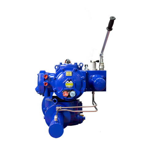
Bernard Controls EZ Series Instructions for use
Bernard Controls
Bernard Controls FSE Series User guide
Bernard Controls
Bernard Controls AQ Logic Series User guide
Bernard Controls
Bernard Controls ST Series Installation manual

Bernard Controls
Bernard Controls AQ Logic Series User guide
Bernard Controls
Bernard Controls AT SWITCH RANGE User guide
Bernard Controls
Bernard Controls AQL Range User guide
Bernard Controls
Bernard Controls SD Series Instructions for use
Bernard Controls
Bernard Controls SQX Series Installation manual
Bernard Controls
Bernard Controls AQ SWITCH 150-1000 User guide
