Berner Aura ARA1036 Installation and operating instructions

READ AND SAVEREAD AND SAVE
READ AND SAVE
THESE INSTRUCTIONSTHESE INSTRUCTIONS
THESE INSTRUCTIONS
No.: II-500
Date: January, 2011
© Copyright 2011 Berner International Corporation
Installation &
Maintenance Instructions
WARNING FOR FUEL BURNING EQUIPMENT:
Sufficient air is needed for proper combustion and exhausting of gases through the flue (chimney) of fuel burning equipment to
preventbackdrafting. Followtheheatingequipmentmanufacturer’sguidelineandsafetystandardssuchasthosepublishedby
the National Fire Protection Association (NFPA), and American Society for Heating, Refrigeration and Air Conditioning
Engineers (ASHRAE), and local code authorities.
UNCRATING
This unit was quality inspected and tested immediately prior to packaging and was in operating condition at that time. Check the
shipping carton and unit for any damage that may have occurred during shipment. If damage is found, notify the shipping company
immediately.
The AURA Series air door is shipped completely assembled. Remove the accessory box and the louvered discharge grille (wrapped in
protective paper) from the carton. Remove the AURA Series air door from the carton. See Figure 1. Immediately upon unpacking the
unit, verify that the rating nameplate agrees with the electric supply available.
Do NOT attach the louvered discharge grille or perforated intake grille at this time.
BERNER INTERNATIONAL CORPORATION
New Castle, Pennsylvania
724-658-3551 • 1-800-245-4455 • www.berner.com • airdoors@berner.com
WARNING: TO REDUCE THE RISK OF FIRE, ELECTRIC SHOCK, OR INJURY TO PERSONS, OBSERVE THE
FOLLOWING:
A. Use this unit only in the manner intended by the manufacturer. If you have any questions, contact the manufacturer.
B. Before servicing or cleaning unit, switch power off at service panel and lock the service disconnecting means to prevent
power from being switched on accidentally. When the service disconnecting means cannot be locked, securely fasten a
prominent warning device, such as a tag, to the service panel.
C. Installation work and electrical wiring must be done by qualified person(s) in accordance with all applicable codes and
standards, including fire-rated construction.
D. Sufficient air is needed for proper combustion and exhausting of gases through the flue (chimney) of fuel burning equipment
to prevent back drafting. Follow the heating equipment manufacturer’s guideline and safety standards such as those
published by the National Fire Protection Association (NFPA), and the American Society for Heating, Refrigeration and Air
Conditioning Engineers (ASHRAE), and local code authorities.
E. When cutting or drilling into wall or ceiling, do not damage electrical wiring and other hidden utilities.

FIGURE 1 - Contents
Each AURA Series carton contains the following pre-assembled
components:
✓(1) AURA air door unit
✓(1) Louvered discharge grille
✓(1) Perforated intake grille
✓(2) Plastic snap ring bushings
✓(6) No. 6 x ¾ Phillips head screws
✓(1) Remote selector switch
Optional Accessories
✓Wall mounting plate
✓Perforated back adapter
✓Solid back adapter
✓Solid back adapter (with or without lights)
I. MOUNTING INSTRUCTIONS
(All Models)
A. Before mounting the unit, check the supporting structure to
verify that it has sufficient load-carrying capacity to support
the weight of the unit(s). The mounting hardware (supplied
byothers)shouldbecapable of supporting a minimum ofthree
(3) times the weight of the unit. See Table 1.
B. Nothing shouldinterferewith the curtainofair developed when
the discharge grille vanes are directed 20° toward the door
opening. If the air stream strikes any obstruction (the top
edge of the doorway, a door opening device, etc.), the effec-
tiveness of the unit will be greatly reduced.
TABLE 1 - Unit Weight
- 2 -
MODEL Net Weight
Ambient (lbs)
Net Weight
Heated (lbs)
ARA1036 120 130
ARA1042 135 145
ARA1048 158 168
ARA1060 185 195
C .For optimum performance, the bottom of the unit (discharge
grille) should be a maximum of 1” above the top of the door
opening with the unit mounted flush to the wall. If the unit
must be mounted higher, it must be spaced out from the wall
3/8” for every inch the unit is above the door opening (maxi-
mum recommended mounting height of 8’). Where possible
(installation site permitting), for optimum protection, any void
between the air door and the wall should be sealed along the
full length of the unit.
D. Do not block (obstruct) the air intake grille. Insufficient air
flow can cause the unit to overheat.
E. Electric heated units should have:
1. A minimum clearance of at least 4” between the sides and
top of the unit and any combustible material.
2. A minimum clearance of at least 6’ between the bottom of
the unit and the floor.
Proceed to either Suspended or Wall Mounting Instruc-
tions.
II. SUSPENDED MOUNTING
A. NO BACK ADAPTOR: Figure 2
1. Suspend the AURA Series air door on the inside of the
building with the louvereddischargegrillefacingthe door
opening. See Figure 2.
2. Mount and level the air door by connecting four (4) 5/16 -18
threaded rods or other suitable hardware (supplied by oth-
ers) to the (4) 5/16-18 threaded inserts located on top of the
unit.
FIGURE 2 - Suspension Mount without Back Adapter

- 3 -
B. WITHBACKADAPTER:Figures3&4
1. The unit may be mounted with the louvered discharge
grille facing toward the door opening, or the interior of
the building (electric heated models only). See Figures
3 and 4.
2. Figure3installation (louvered discharge grille facing in-
terior of the building). Follow instructions A & B above.
3. Figure4installation (louvered discharge grille facing in-
terior of the building). A maximum of 6” between the
wall and intake grille is required. Install the back adap
tor at this time. Follow instructions 2 under Item A.
FIGURE 3 - Suspension Mount with Back Adapter
C. ABOVECEILING:Figure5
Follow instructions 1 & 2 under Item A. See Figure 5. The
bottom of the unit can be exposed for easy servicing.
D. DO NOT install the perforated intake grille or the lou-
vered air discharge grille at this time. Proceed to Section
IV ELECTRICAL CONNECTIONS.
III. WALL MOUNTING
(Optional Wall Mounting Bracket Required)
See Figures 6-10
A. When the AURA Sseries air door is for wall mounting, four
5/16” shoulder bolts will be pre-assembled on the back of the
unit (opposite the perforated intake grille).
B. The wall mounting plate is designed to fit flush with the back
of the entire AURA door.
C. Determine the exact location of the air door unit. Position the
center of the wall mounting plate over the center of the door
opening with the larger opening of the key hole slots facing
up.
For optimum performance, the bottom of the mounting plate
should be no more than 1” above the top of the door opening.
STANDARD WALL MOUNTING: Figure 7A. The wall
mounting plate thickness provides a natural 13/8” space which
allows for mounting up to 4” above the opening.
HIGH WALL MOUNTING: If the wall mounting plate must
be mounted higher than 4” above the door opening, it must be
spaced out from the wall 3/8” for every inch the unit is above
the door opening. See Figure 7B.
For optimum performance, do not exceed the recommended
maximummountingheight of8’above the finishedfloor. For
optimum protection, any void between the mounting plate and
the wall should be sealed along the full length of the mounting
plate.
FIGURE 4 - Suspension With Back Adapter Reverse Flow
FIGURE 5 - In-Ceiling Suspension Mount Without Adapter

- 4 -
D. Mark the wall in the centers of the (4) ½” round holes pro-
vided on the mounting plate. See Figure 6. If the holes on
the mounting plate are not located where suitable support is
available for the unit, drill new holes in the space provided on
the mounting plate.
E. Drill the fourholesas marked onthewalland attach themount-
ing plate to the wall (mounting hardware by others).
F. Raise the air door with the discharge opening facing down
toward the floor. While holding the unit level, slide the heads
of the shoulder bolts into the larger hole of the key-
hole slots of the mounting plate. Lower the unit into place,
keeping both ends level, allowing it to rest flush with the
mounting plate. See Figure 9.
G. After attaching the unit to the mounting plate, check to ensure
the unit is seated and flush with the mounting plate on all four
sides.
H. Do not install the perforated intake grille or the louvered dis-
charge grille at this time.
Proceed to Section IV - Electrical Connections.
FIGURE 6 - Wall Mounting Plate, Wall Marking
FIGURE 9 - Mounting to Wall Plate
FIGURE 7A - Standard Wall Mounting
FIGURE 8 - Wall Mount With Optional Wall Plate
FIGURE 7B - High Wall Mounting

- 5 -
IV.ELECTRICAL CONNECTIONS
A. All electrical wiring and connections MUST be performed
by qualified personnel in accordance with the National elec-
trical Code ANSI/NFPA No. 70 (latest edition) or, in Canada,
the Canadian Electrical Code, Part 1-C.S.A. Standard C22.1
and local codes and regulations.
WARNING: DONOTOPERATETHISFANWITHANY
SOLID STATE SPEED CONTROL DEVICE.
B. Check the rating nameplate on the top of the unit, or inside
the bottom access cover, for supply voltage and current
requirements. See Figure 11. A separate line voltage supply
with a suitable branch circuit protection device should be run
directlyfromthe main electricalpanelof the unit. Adisconnect
switch for each branch circuit is a required part of this
installation.
C. All field wiring must be copper with a minimum insulation of
60°C within approved conduit. If any of the wire supplied
with the unit must be replaced, it must be replaced with cop-
per wiring with a minimum insulation of 90°C.
D. Access the wiring compartment, See Figure 11, by lowering
the bottom hinged access cover. Remove the two ¼” bolts
located on the intake side of the unit and the access cover will
swing down to rest in the vertical position exposing the wir-
ingcompartment. Ifdesired,theaccess cover may be removed
by grasping both sides of the access cover and pressing in on
the spring loaded hinges. See Figure 11.
E. The top of the unit has two knockouts on each side allowing
for a left hand or right hand power connection. Remove the
required knockout and connect the power supply to the unit.
F. A wiring guard, See Figure 12, is mounted on the right of the
air intake of the unit. The wiring guard is reversible, so it
may be mounted on either side of the unit. Remove the ¼”
mounting bolt. Clearance holes enable the wiring guard to be
removed without disturbing the ¼” shoulder bolts.
FIGURE 12 - Wiring Guard
FIGURE 10 - In-Ceiling Mount With Optional Wall Plate
FIGURE - 11 Access Cover Removal
G. The wiring tray, directly below the power supply connection,
also has two knockout slugs. Remove the required knockouts
and insert one plastic snap ring bushing into each hole cre-
ated.
H. Install the Remote Selector Switch in accordance with the
directions furnished with the selector switch. Each switch is
capable of operating up to three units at 120 VAC and up to
six units at 208/240 VAC. Make the switch connections ac-
cording to the applicable wiring diagram..
I. Connect all power and control circuit wires to the terminal
strip located on the right hand side of the wiring tray. Refer
to the wiring diagram.
J. If your unit was provided with a Time Delay-Off Relay, it
will be factory set at 15 seconds. If a longer delay-off is de-
sired, adjust the rotary dial clockwise with a small screwdriver
to preferred time setting. Each hashmark stands for 60 sec-
onds with a maximum setting of up to 300 seconds. See Fig-
ure 13.
K. Reinstall the wiring guard so that it covers all of the wires
used to make the connections to the terminal strip. Reinstall
the ¼” mounting bolt. See Figure 12.

- 6 -
L. Reinstall the hinged access cover by positioning one hinge
into the corresponding catch located on the unit. Raise the
other hinge to the unit, when the catch is located press in the
hinge and release it into the catch. Swing the access cover
into place and align the mounting holes with the threaded in-
serts on the unit. Reinstall the two ¼” bolts. See Figure 11.
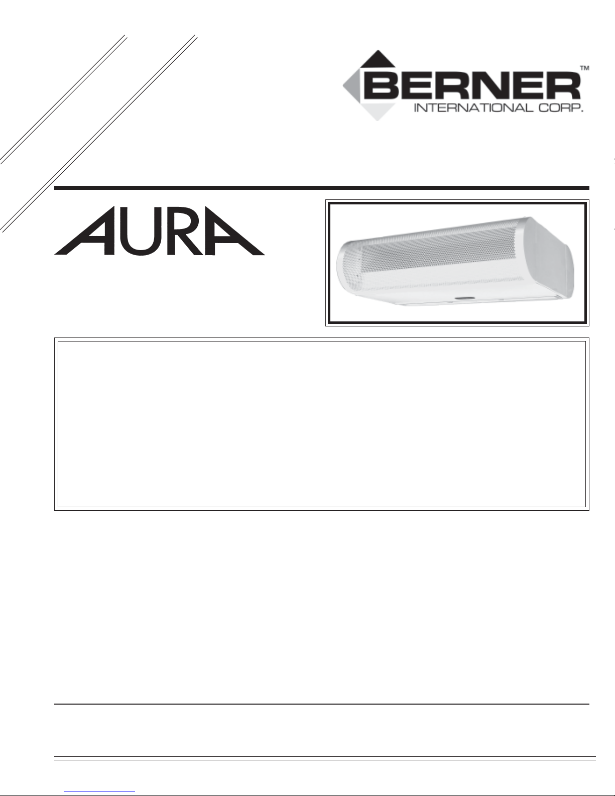
M. Attach the perforated intake grille on the ¼” shoulder bolts of
the unit. See Figure 15. While holding the grille level with
the unit, align the keyhole slots with the shoulder bolts. Press
the grille firmly against the unit and push down until the grille
rests flush with the bottom of the unit.
N. Attach the louvered discharge grille to the unit with the six
(6) No. 6 x ¾” phillips head screws provided. See Figure 14.
O. Switch on the power at the service disconnect. Turn on the
unit at the selector switch and check the sequence of opera-
tion against that provided on the wiring diagram. Proceed to
Section V: Operation and Air Flow Adjustment.
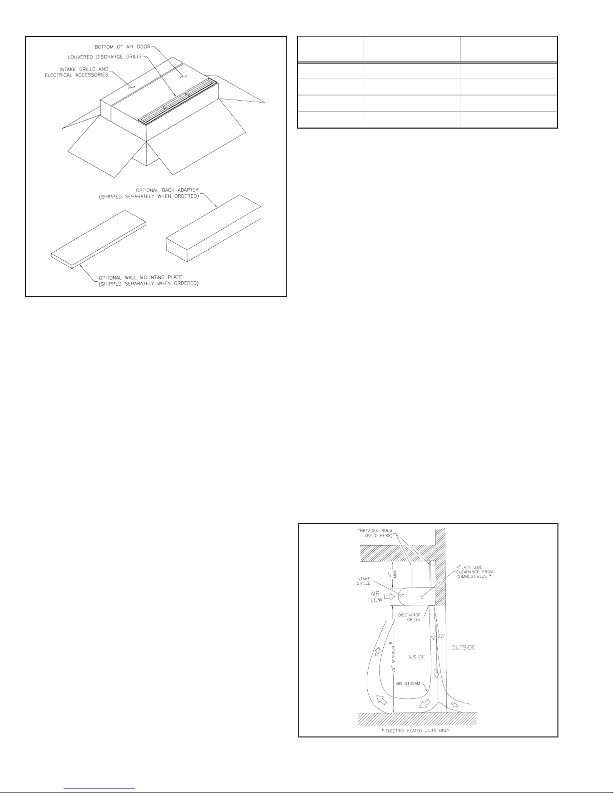
C. Adjusttheairdirectional vanes in the louvered dischargegrille
so the split location is approximately 3” outside the doorway.
FIGURE 13 - Time Delay Adjustment
FIGURE 14 - Louvered Discharge Grille Installation
V. OPERATION AND
AIR FLOW ADJUSTMENT
A. With the air curtain operating on high speed, and the door in
its full open position, check to see that nothing is obstructing
the air flow at the louvered discharge grille.
B. Find the air stream “split” location. Hold a handkerchief, by
its top corners, approximately 12” above the floor. Gently
move the handkerchief back and forth in the doorway. Make
sure the air is being directed to both the inside and the out-
side. The split locations indicated when the handkerchief is
vertical with minimal flutter.
VI. PREVENTIVE MAINTENANCE &
SERVICE
A. CAUTION: ELECTRIC SHOCK HAZARD Disconnect
power whenever servicing unit. More than one discon-
nectmay be required to de-energize unit.
Any service performed on the AURA Series air door MUST
be done by qualified personnel.
Berner air doors require very little servicing. All parts are
easily accessible for periodic inspection and maintenance.
Units should be cleaned at least twice a year. Your particular
application (the amount of dirt and dust in the air) and location
of the unit(s) will determine how often your unit(s) will need
tobecleaned and serviced. All motorshavepermanently lubri-
cated, sealed, sleeve bearings and require no maintenance.
B. TO PERFORM PREVENTIVE MAINTENANCE, RE-
MOVE THE LOUVERED DISCHARGE GRILLE, THE
PERFORATEDINTAKEGRILLEANDTHEBOTTOM
ACCESS COVER.
1. Remove the discharge grille by unscrewing the six (6)
Phillips head screws located on the inside edge of the
grille. See Figure 14.
2. Remove the intake grille by lifting up on both sides with
equal force. Once the grille is detached, pull the grille
away from the unit until it clears the shoulder bolts. This
will expose the bottom access cover mounting bolts and
the heating coils (if applicable).
3. Remove the bottom two ¼” mounting bolts on the intake
side of the unit. Swing the access cover to rest in the
vertical position. Grasp both sides of the access cover
and press in on the spring loaded hinge. This will re
lease theaccesscover from the unitandexposethe blower
mounting plate. See Figure 11.
FIGURE 15 - Attaching Intake Screen or Back Adapter

4. Use an industrial vacuum or compressed air to remove dirt build-up from the inside of the access cover, air inlet grille, blower
wheels/housings, interior of the unit, and heating coils (if applicable). Remove the dirt build-up from the blower wheels
through the discharge openings on the blower plate.
5. If the unit is extremely dirty the blower plate (containing the motor and fan wheels) may be removed to further access the
internals.
C. TO REMOVE THE BLOWER PLATE:
1. Unplug the wiring harness from the motor.
2. Blower plate removal - Remove the four (4) ¼” bolts located on the four corners of the blower mounting plate.
This will release the blower plate from the unit. Remove the blower plate by lowering it straight down and out of the unit. All
internals are attached to the blower plate allowing for service or repair to be done on the ground away from the unit.
3. To reassemble the unit reverse steps 1 through 5.
- 7 -
Serial No. __________________________ Model No.__________________________ Date of Purchase____________________
Berner International warrants all new equipment to be free of defects in workmanship and material for a period of five years (5 years)
on unheated models and two years (2 years) on heated models from the original date of shipment, provided the equipment has been
properly cared for, installed and operated in accordance with the limits specified on the nameplate and The Company’s instructions.
The Company will correct by repair or replacement, at its option and expense, any proven defects in said apparatus, subject to the
above conditions, provided that immediate written notice of such defects is given to the Company. The warranty does not include
any labor incurred for the removal or installation of defective part(s). The Company reserves the right to inspect, or have inspected
by a qualified representative, any apparatus at the place of installation before authorizing repair or replacement. Repair or
replacement will be made F.O.B. factory with any applicable transportation charges to be borne by the customer. Merchandise not of
the Company’s manufacture supplied in piece, or in component assemblies, is not covered by the above warranty, but the Company
will give the customer the benefit of any adjustment as made with the Manufacturer.
This warranty is void if the apparatus has been tampered with in any way or shows evidence of misuse.
The Company will not assume any expense or liability for repairs made outside its factory without proper written consent from its
service manager, nor for any transportation charges on apparatus returned to the factory without written authorization by the
Company.
Nothing in the above warranty provisions, however, shall impose any liability or obligation of any type, nature or description upon
Berner International if Berner has not received payment in full for the apparatus in question.
THEREARENOWARRANTIESWHICHEXTENDBEYONDTHEDESCRIPTIONONTHEFACEHEREOFINCLUDINGTHE
IMPLIEDWARRANTYOFMERCHANTABILITYANDFITNESSFORAPARTICULARPURPOSE.
LIMITATIONOFDAMAGES
Notwithstandinganythingtothe contrary above,customer’sexclusiveremedyfor anyandalllossesor damages resultingfromthe
saleofTheCompany’sequipment underthisagreement,includingbut notlimitedto,any allegationsofbreachof warranty,breach
ofcontract,negligenceorstrict liability,shall be limited, atTheCompany’soption, to eitherthereturnof the purchaseprice orthe
replacementoftheparticularequipmentforwhichaclaimismadeand proved. Innoevent shallTheCompany beliablefor any
special,consequential,incidentalor indirect losses ordamagesfromthesaleof The Company’sequipmentunderthisagreement.
WARRANTY

TROUBLESHOOTING
SYMPTOMS CAUSE REMEDY
NO AIR • Power supply line open (no power) • Check power source, check method of control in ON
position
• Fuse blown/circuit breaker tripped • Replace fuse(s)/reset breaker
• Motor overload tripped • Internally protected motor - should reset automatically
after cool-down, if not replace motor.
• Failed switch • Replace switch
MOTOR RUNNING/FANS ARE NOT ROTATING
• Broken or flexible hub • Replace fan sleeve/reengage coupling
• Shaft rotating inside fan • Tighten set screws/tighten fan on shaft
• Belt driven units/belt broken • Replace belts
ELECTRICAL CONTROLS NOT FUNCTIONING WHEN DOOR IS OPEN
• Selector switch is in off position • Turn switch to “ON” position
• Door limit switch not operating • Repair or replace limit switch
MINIMUM AIR • Air directional discharge vanes misadjusted • Adjust vanes to proper position, see instructions
• Inadequate intake clearance • Move air curtain or remove obstruction
• Provide adequate space for air curtain
• Blower motor operates below speed • Improve voltage
• Fan rubbing against housing • Free fan from housing
• Fan wheels clogged with dirt • Clean and vacuum fan wheels
AIR IS NOT HITTING • Air stream to weak • Adjust nozzle to proper position, adjust motor speed;
FLOOR see installation instructions
• Air stream hits obstruction • Remove obstruction or reposition air curtain (move out
3/8” for every 1” up from the door)
• Negative pressure • Relieve negative pressure by providing make-up air
UNEVEN AIR • Shaft rotating inside fan • Tighten set screws
• One motor not operating • Repair or replace motor
EXCESSIVE AIR • Nozzle not angled out far enough • Adjust nozzle angle to outside
MOVEMENT AT • Unit too powerful • Adjust motor speed
DOORWAY • Air movement too cold • Add auxiliary heat to overcome wind chill factor
• Pushing air outside building • Adjust discharge angle back into building, adjust motor
speed
SEE AIR IS NOT HITTING FLOOR SYMPTOMS
ELECTRICALLY HEATED MODELS
NO HEAT • Switch turned to “ON” position • Replace switch or check wiring
• Thermostat not set properly • Change thermostat setting
• Coils burned out due to lack of air • Correct airflow problem; replace coils
• Automatic reset thermal cutout failed in open position • Replace automatic thermal cutout
• Manual reset thermal cutout tripped • Reset manual thermal cutout
NOT ENOUGH HEAT • Thermostat in wrong location - thermostat too • Move thermostat away from air stream
close to discharge
• Improper voltage • Supply proper voltage
• Thermostat not set properly • Change temperature setting
TOO MUCH HEAT • Thermostat in wrong location • Move thermostat closer to air stream
• Thermostat not set properly • change temperature setting
• Insufficient air over coil • Remove restriction on intake
• Improper voltage • Supply proper voltage
© Copyright 2011, Berner International Corporation
●
New Castle, PA
●
724-658-3551
●
1-800-245-4455
●
www.berner.com
This manual suits for next models
3
Table of contents
Other Berner Air Conditioner manuals
Popular Air Conditioner manuals by other brands

Carrier
Carrier Fan Coil 42B Installation, operation and maintenance manual

Sanyo
Sanyo SAP-CMRV1923GJH Technical & service manual

Hitachi
Hitachi RAM-55QH4 Service manual

Airxcel
Airxcel Marvair ComPac II AVHDA90 Installation & operation manual

Shinco
Shinco SPF1-10C owner's manual

Dometic
Dometic BRISK AIR 579 SERIES installation instructions

MrCool
MrCool Signature Series Owners & installation manual

Fuji Electric
Fuji Electric RD-60FA Service manual

Mitsubishi Electric
Mitsubishi Electric Mr.Slim PEA-M200 installation manual

Nortek
Nortek AB 225 Installation and operating manual

Hitachi
Hitachi RAD-25NH4 Service manual

INVENTOR
INVENTOR V3MFI-24 user manual