Berner BBN-24 User manual

- 1 -
Instruction manual
multilingual
BBN-24
Art. No.: 001668

- 2 -
#
D
Gebrauchsanleitung
3
UK
Instruction Manual
9
F
Manuel de l'Utilisateur
15
BG
Инструкции за употреба
21
DK
Brugsanvisning
27
EST
Kasutusjuhend
33
FIN
Käyttöohjeet
39
GR
Οδηγίες χρήσης
45
IT
Istruzione
51
HR
Upute za korištenje
57
LV
Lietošanas instrukcija
63
LT
Naudojimo instrukcijos
69
NL
Gebruiksaanwijzing
75
PL
Instrukcja użycia
81
PT
Instruções de uso
87
RO
Instructiuni de folosire
93
S
Användningsinstruktioner
99
SK
Inštrukcie na používanie
105
SLO
Navodila za uporabo
111
E
Instrucciones
117
CZ
Návod k použití
123
HU
Használati útmutató
129
TR
Kullanım için talimatlar
135

- 3 -
Gebrauchsanweisung BBN-24
Deutsch
Für eine sichere und sachgerechte Anwendung die Gebrauchsanleitung
sorgfältig lesen und für spätere Verwendungen aufbewahren.
Sicherheit und Verwendung
Lesen und beachten Sie immer die beiliegenden Sicherheitshinweise.
Bestimmungsgemäße Verwendung
•Optische Höhenübertragung.
•Optische Distanzmessung mit Distanzstrichen.
•Horizontale Winkelmessung.
Sachwidrige Verwendung
•Verwendung des Produktes ohne Instruktion.
•Verwendung außerhalb der Einsatzgrenzen.
•Durchführung von Umbauten oder Veränderungen am Produkt.
•Öffnen des Produktes mit Werkzeugen, sofern nicht ausdrücklich für
bestimmte Fälle erlaubt.
•Verwendung des Produkts mit erkennbaren Mängeln oder Schäden.
•Verwendung von Zubehör anderer Hersteller, das vom Hersteller nicht
ausdrücklich genehmigt ist.
•Direktes Zielen in die Sonne.
•Unzureichende Schutzmaßnahmen am Einsatzort.
Einsatzgrenzen
Siehe Kapitel „Technische Daten“.
Einsatz in dauernd für Menschen bewohnbarer Atmosphäre geeignet, nicht
einsetzbar in aggressiver oder explosiver Umgebung.
Vor jeder Inbetriebnahme
Das Produkt vor der Inbetriebnahme auf eventuelle Beschädigungen
überprüfen.

- 4 -
Wartung und Transport
•Transportieren Sie das Produkt entweder im originalen Transportbehälter
oder aufrecht auf einem Stativ.
•Transportieren Sie das Produkt niemals ungesichert in einem Fahrzeug.
•Setzen Sie das Instrument keinen hohen Temperaturen aus, wie z.B. bei
direkter Sonneneinstrahlung in einem Fahrzeug.
•Obwohl das Produkt wasser- und staubgeschützt ist, sollte es nicht für
längere Zeit im Regen stehen.
•Reinigen Sie das Gerät und Zubehör nach jedem Gebrauch.
•Benutzen Sie niemals flüchtige Flüssigkeiten (Verdünner oder Benzin)
oder sonstige organische Lösungsmittel zur Reinigung des Instruments.
•Bewahren Sie das Instrument an einem trockenen, normal temperierten
Raum auf.
•Kontrollieren Sie regelmäßig vor Gebrauch die Justierung des Produktes,
um die Genauigkeit zu erhalten oder schicken Sie es in eine autorisierte
Werkstatt zur Überprüfung.
Instrument Komponenten
1) Optische Zielhilfe
6) Objektiv
2) Okular
7) Endlostrieb (beidseitig)
3) Horizontalkreis
8) Justierschrauben-Abdeckung
4) Fußschraube
9) Spiegel
5) Fokussierschraube
10) Dosenlibelle
11) Stativanschlußgewinde 5/8“
Lieferumfang
•1 x BBN-24 Instrument
•1 x Transportbehälter
•1 x Senklot mit Schnur
•1 x Sicherheitshinweis
•1 x Justierstift
1
1
10
5
6
3
2
4
7
9
8
11

- 5 -
Aufstellung
•Bei Verwendung eines Statives dies bis zur bequemen
Beobachtungshöhe ausziehen und Beine festklemmen.
•Beinspitzen fest in den Boden treten, den Stativkopf möglichst horizontal
ausrichten.
•Das Instrument mit der zentralen Anzugsschraube auf der Grundplatte
befestigen.
Horizontieren
•Die drei Fußschrauben so verstellen, bis die Luftblase der Dosenlibelle
sich innerhalb des Kreises eingespielt hat.
•Den Restfehler der Neigung gleicht der Kompensator automatisch aus.
Bedienung Fadenkreuz einstellen
•Das Objektiv gegen einen hellen Hintergrund richten.
•Durch das Okular schauen und durch Drehen des Okulars das
Fadenkreuz scharf einstellen.
Bedienung Ziel suchen und einstellen
•Mittels der optischen Zielhilfe das Fernrohr auf ein Ziel ausrichten.
•Durch Drehen der Fokussierschraube das Bild klar einstellen.
•Durch Drehen am Endlostrieb das Fadenkreuz auf die Mitte des Zieles
ausrichten.

- 6 -
Bedienung Höhenablesung
•Nivellierlatte senkrecht am Ziel aufstellen.
•Instrument horizontieren und auf Nivellierlatte fokussieren.
Bedienung Abstand messen und berechnen
LΔ= Abstand Instrument zum Ziel
Formel: LΔ= l1–l2x 100
Beispiel: LΔ= 1,016 m –0,893 m x 100 = 12,3 m
Ablesung l1= 1,016 m
Ablesung lx= 0,956 m
Ablesung l2= 0,893 m

- 7 -
Bedienung Winkelmessung
•Instrument horizontieren.
•Ziel A anvisieren.
•Horizontalkreis auf „0“ drehen.
•Ziel B anvisieren.
•Horizontalwinkel ablesen.
Prüfen und Justieren
Dosenlibelle
•Instrument auf Stativ befestigen.
•Luftblase der Dosenlibelle mittels Fußschrauben zentrieren.
•Fernrohr um 180° drehen.
•Bei Abweichung die Hälfte des Ausschlages durch Drehen der
Justierschrauben der Dosenlibelle korrigieren.
•Fernrohr wieder um 180° zurückdrehen.
•Luftblase der Dosenlibelle mittels Fußschrauben zentrieren und Vorgang
wiederholen, bis die Luftblase in der Mitte des Kreises bleibt.
Kompensator prüfen
•Instrument auf Stativ befestigen und horizontieren.
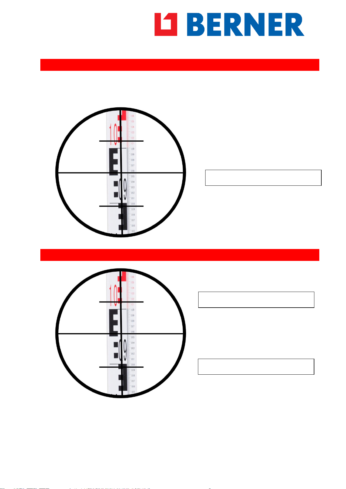
•Ein Ziel (Nivellierlatte) in ca. 10 m Entfernung fokussieren und eine
Ablesung Ladurchführen.
•Eine Fußschraube ½ Umdrehung nach links oder rechts drehen.
•Das Fadenkreuz muss sich wieder in die vorige Position der Ablesung La
einpendeln.
•Ist dies nicht der Fall, so muss das Nivellierinstrument zur Überprüfung
an eine autorisierte Werkstatt oder den Hersteller geschickt werden.
Ziellinie prüfen und justieren
•Eine Strecke von ca. 30 m im flachen Gelände wählen.
•An beiden Endpunkten (A, B) je eine Nivellierlatte aufstellen.
•Instrument in die Mitte zwischen A und B aufstellen und horizontieren.
•Beide Latten ablesen und den Höhenunterschied ΔH1 berechnen.
•Instrument ca. 1 m vor Latte A aufstellen, beide Latten ablesen und ΔH2
berechnen.
•Ist die Differenz größer 3 mm die Ziellinie justieren.
1
2

- 8 -
•Die Ziellinie wird durch Drehen an den Justierschrauben am Okular
justiert.
•Wiederholen Sie den Prüfvorgang nach einer Justierung der Ziellinie.
Technische Daten BBN 24
Fernrohr Länge 193 mm
Bild Aufrecht
Durchmesser 36 mm
Vergrößerung 24 x
Gesichtsfeld 1°30‘
Kürzeste Zielweite 0.5 m
Horizontalkreis Durchmesser 117 mm
Teilung 400 gon
Kompensator Bereich ± 15‘
Genauigkeit 1 km Doppelnivellement ± 2.5 mm
Dosenlibelle Empfindlichkeit 8‘ / 2 mm
Gewicht Instrument 1.9 kg
Behälter 1.1 kg
Anschluss Zentralanzugsschraube 5/8“
Konstanten Multiplikation 100
Addition 0
Originaltext ist Deutsch, alle anderen Sprachen sind Übersetzungen des
Originaltextes.
Version Juli 2022 –Index 02

- 9 -
Instruction manual BBN-24
English
For safe and proper use, read the instructions carefully and keep them for
later use.
Safety and use
Always read and observe the enclosed safety instructions.
Permitted use
•Optical height readings.
•Optical distance measuring with stadia readings.
•Horizontal angle measurement.
Prohibited use
•Use of the product without instruction.
•Use outside the intended use and limits.
•Implementation of modifications or changes to the product.
•Opening the product with tools, unless expressly permitted for certain
cases.
•Use of the product with recognizable defects or damage.
•Use of accessories from other manufacturers that have not been
expressly approved by manufacturer.
•Aiming directly into the sun.
•Inadequate safeguards at the place of use.
Limits of use
Refer to section "Technical data". Suitable for use in an atmosphere
appropriate for permanent human habitation: not suitable for use in
aggressive or explosive environments.
Before every use
Check the product for damage before commissioning.

- 10 -
Care and Transport
•Transport the product either in the original transport container or upright
on a tripod.
•Never transport the product unsecured in a vehicle.
•Do not expose the instrument to high temperatures, such as in direct
sunlight or in a vehicle.
•Although the product is water and dust proof, it should not be left in the
rain for long periods of time.
•Clean the device and accessories after each use.
•Never use volatile liquids (thinner or benzine) or other organic solvents to
clean the instrument.
•Store the instrument in a dry room at a normal temperature.
•Check the adjustment of the product regularly before use in order to
maintain the accuracy or send it to an authorized workshop for checking.
Instrument Components
1) Optical aiming aid
6) Objective
2) Ocular
7) Endless drive (both sides)
3) Horizontal circle
8) Adjustment screw cover
4) Foot screw
9) Mirror
5) Focusing Knob
10) Circular vial
11) Tripod connection 5/8“
1
1
10
5
6
3
2
4
7
9
8
11

- 11 -
Scope of Delivery
•1 x BBN-24 Levelling instrument
•1 x Transport box
•1 x Plumb bob with cord
•1 x Instruction manual
•1 x Adjustment tool
Setting up
•When using a tripod, pull it out to a comfortable observation height and
clamp the legs.
•Kick the tips of your legs firmly into the ground, align the tripod head as
horizontally as possible.
•Fasten the instrument to the base plate with the central tightening screw.
Level up
•Adjust the three foot screws until the air bubble in the circular vial has
settled within the circle.
•The compensator automatically compensates for the residual error in the
inclination.
Adjust the crosshair
•Point the objective against a light background.
•Look through the ocular and focus the crosshairs by turning it.
Search and aim target
•Align the telescope with a target using the optical aiming aid.
•Adjust the picture clearly by turning the focusing knop.
•Align the cross hairs with the centre of the target by turning the endless
drive.

- 12 -
Height reading
•Set up the levelling staff vertically on the target.
•Level the instrument and focus on the levelling staff.
Measure and calculate distance
LΔ= Distance Instrument to target
Formula: LΔ= l1–l2x 100
Example: LΔ= 1,016 m –0,893 m x 100 = 12,3 m
Reading l1= 1,016 m
Reading lx= 0,956 m
Reading l2= 0,893 m

- 13 -
Angle measurement
•Level the instrument.
•Aim at target A.
•Turn the horizontal circle to "0".
•Aim at target B.
•Read off the horizontal angle.
Checking and adjustment
Circular Vial
•Mount the instrument on a tripod.
•Centre the air bubble in the circular level using foot screws.
•Turn the telescope 180 °.
•If there is a deviation, correct half of it by turning the adjusting screws on
the circular vial.
•Turn the telescope back by 180 °.
•Centre the air bubble in the circular vail using the foot screws and repeat
the process until the air bubble remains in the centre of the circle.
Checking Compensator
•Mount the instrument on a tripod and level it.
•Focus a target (levelling staff) approx. 10 m away and take a reading La.
•Turn a foot screw ½ a turn to the left or right.
•The crosshairs must settle back into the previous position of the reading
La.
•If this is not the case, the levelling instrument must be sent to an
authorized workshop or the manufacturer for inspection.
Check and adjust line of sighting
•Choose a distance of approx. 30 m in flat terrain.
•Set up a levelling staff at both end points (A, B).
•Set up the instrument in the middle between A and B and level it.
•Read off both staffs and calculate the difference in height ΔH1.
•Set up the instrument approx. 1 m in front of staff A, read off both staffs
and calculate ΔH2.
•If the difference is greater than 3 mm, adjust the line of sight.
•The line of sight is adjusted by turning the adjusting screws on the ocular.
1
2

- 14 -
•Repeat the test procedure after adjusting the line of sight.
Technical Data
Telescope Length 193 mm
Image Upright
Diameter 36mm
Magnification 24x
Field of view 1°30'
Shortest target distance 0.5 m
Horizontal circleDiameter 117 mm
Division 400 gon
Compensator Range ± 15'
Accuracy 1 km double levelling ± 2.5 mm
Vial Sensitivity 8' / 2 mm
Weight Instrument 1.9 kg
Container 1.1 kg
Connection Central tightening screw 5/8"
Constant Multiplication 100
Addition 0
Original text is German, all other languages are translations of the original
text.
Version July 2022 - Index 02

- 15 -
Manuel de l'Utilisateur BBN-24
French
Pour pouvoir exploiter pleinement le potentiel du produit, lisez attentivement
le mode d’emploi pour le conserver ensuite soigneusement.
Sécurité et Utilisation
Lisez et respectez toujours les consignes de sécurité ci-jointes.
Utilisation prévue
•Lecteurs optiques de hauteur.
•Mesure de distance optique avec lecture stadimétriques.
•Mesure d'angle horizontal.
Utilisation non conforme prévisible
•Utilisation du produit sans instruction.
•Utilisation en dehors de l'utilisation et des limites prévues.
•Mise en œuvre de modifications ou de changements.
•Ouverture du produit avec des outils, sauf autorisation expresse dans
certains cas.
•Utilisation du produit avec des défauts ou des dommages.
•Utilisation d'accessoires d'autres fabricants qui n'ont pas été
expressément approuvés par Gottlieb Nestle GmbH.
•Viser directement dans le soleil.
•Protections inadéquates sur le lieu d'utilisation.
Limites d'utilisation
Reportez-vous à la section « Spécification ». Le produit est conçu pour
fonctionner dans des environnements habitables en permanence et ne peut
être utilisé dans des milieux agressifs ou susceptibles de provoquer des
explosions.
Avant chaque démarrage
Avant d’utiliser le produit, vérifiez-le pour tout dommage.

- 16 -
Soins et Transport
•Transportez le produit soit dans le conteneur de transport d'origine, soit
debout sur un trépied.
•Ne transportez jamais le produit non sécurisé dans un véhicule.
•N'exposez pas l'instrument à des températures élevées, comme à la
lumière directe du soleil ou dans un véhicule.
•Bien que le produit soit étanche à l'eau et à la poussière, il ne doit pas
être laissé sous la pluie pendant de longues périodes.
•Nettoyez l'appareil et les accessoires après chaque utilisation.
•N'utilisez jamais de liquides volatils (diluants ou benzène) ou d'autres
solvants organiques pour nettoyer l'instrument.
•Stockez l'instrument à une température normale.
•Vérifiez régulièrement le réglage du produit avant utilisation afin d'en
conserver l'exactitude ou envoyez-le à un atelier agréé pour vérification.
Composants de l'instrument
1) Viseur
6) Objectif
2) Oculaire
7) Mouvement sans fin (des deux côtés )
3) Cercle horizontal
8) Couvrir de vis d'ajustement
4) Vis calante
9) Miroirs
5) Bouton de mise au point
10) Nivelle circulaire
11) Connexion trépied 5/8“
1
1
10
5
6
3
2
4
7
9
8
11

- 17 -
Contenu de la Livraison
•1 x BBN 24 Instrument
•1 x Caisse de transport
•1 x Plomb à fil
•1 x Mode d’emploi
•1 x Outil de réglage
Opération mise en place
•Lorsque vous utilisez un trépied, tirez-le à une hauteur d'observation
confortable et serrez les pieds.
•Frappez fermement le bout de vos jambes dans le sol, alignez la tête du
trépied aussi horizontalement que possible.
•Fixer l'instrument à la plaque de base avec la vis de serrage centrale.
Opération niveler l'instrument
•Ajustez les trois vis calantes jusqu'à ce que la bulle d'air dans le vivelle
circulaire se soit installée dans le cercle.
•Le compensateur compense automatiquement l'erreur résiduelle
d'inclinaison.
Opération ajuster le réticule
•Pointez l'objectif sur un fond clair.
•Regardez dans l'oculaire et focalisez le réticule en le tournant.
Opération rechercher et viser la cible
•Alignez le télescope sur une avec de l’aide à la Viseur.
•Réglez clairement l'image en tournant le bouton de mise au point.
•Alignez le réticule avec le centre de la cible en tournant les mouvements
sans fin.

- 18 -
Opération lecture de la hauteur
•Installez la mire de nivellement verticalement sur la cible.
•Mettez l'instrument à niveau et concentrez-vous sur la mire.
Opération mesurer et calculer la distance
LΔ= Distance Instrument à la cible
Formule : LΔ= l1–l2x 100
Exemple : LΔ= 1,016 m –0,893 m x 100 = 12,3 m
Lecture l1= 1,016 m
Lecture l1= 0,956 m
Lecture l2= 0,893 m

- 19 -
Opération mesure d'angle
•Nivelez l'instrument.
•Visez la cible A.
•Tournez le cercle horizontal
sur "0".
•Visez la cible B.
•Lire l'angle horizontal.
Vérification et réglage
Nivelle circulaire
•Montez l'instrument sur un trépied.
•Centrez la bulle d'air dans la nivelle circulaire à l'aide des vis calantes.
•Tournez le télescope à 180°.
•S'il y a un écart, corrigez-en la moitié en tournant les vis d'ajustement sur
la nivelle circulaire.
•Retournez le télescope de 180°.
•Centrez la bulle d'air dans la nivelle circulaire à l'aide des vis calantes et
répétez le processus jusqu'à ce que la bulle d'air reste au centre du
cercle.
Chèque de Compensateur
•Montez l'instrument sur un trépied et mettez-le à niveau.
•Focalisez une cible (mise à niveau) env. 10 m et prendre une lecture La.
•Tournez une vis de calantes d'un demi-tour vers la gauche ou la droite.
•Le réticule doit revenir dans la position précédente de la lecture La.
•Si ce n'est pas le cas, l'instrument de nivellement doit être envoyé à un
atelier agréé ou au fabricant pour inspection.
Vérifier et ajuster la ligne de visée
•Choisissez une distance d'env. 30 m en terrain plat.
•Installez une mire de nivellement aux deux extrémités (A, B).
•Placez l'instrument au milieu entre A et B et mettez-le à niveau.
•Lire les deux mires et calculer la différence de hauteur ΔH1.
•Installer l'instrument à env. 1 m devant la mire A, lire les deux mires et
calculer ΔH2.
•Si la différence est supérieure à 3 mm, ajustez la ligne de visée.
1
2

- 20 -
•La ligne de visée est ajustée en tournant les vis vis d'ajustement sur
l'oculaire.
•Répétez la procédure de test après avoir ajusté la ligne de visée.
Spécification
Télescope Longueur 193 mm
Image verticale
Diamètre 36mm
Grossissement 24x
Champ de vision 1°30'
Distance cible la plus courte0,5 m
Cercle horizontal Diamètre 117 mm
Division 400 gon
Plage du compensateur ± 15'
Précision 1 km double nivellement ± 2,5 mm
Sensibilité Bulles circulaires 8' / 2 mm
Poids Instrument 1,9 kg
Conteneur 1.1kg
Connexion vis de serrage central 5/8"
Constante Multiplication 100
Ajout 0
Le texte original est l'allemand, toutes les autres langues sont des
traductions du texte original.
Version Juillet 2022 - Indice 02
This manual suits for next models
1
Table of contents
Languages:
Other Berner Laser Level manuals
Popular Laser Level manuals by other brands

LaserLiner
LaserLiner AutoLite-Laser Green operating instructions

DeWalt
DeWalt DW089LR quick start guide

CONDTROL
CONDTROL XLiner Pento 360 user manual

Futech
Futech MULTICROSS 4D ELECTRONIC user manual

Johnson Level & Tool
Johnson Level & Tool 40-6560 instruction manual

geo-FENNEL
geo-FENNEL MULTI-LINER FL 55 PLUS HP user manual