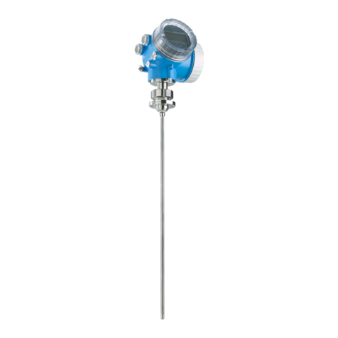
Endress+Hauser Levelflex M FMP45 User manual

KA01052F/00/EN/13.10
71120336
Brief Operating Instructions
Levelflex M FMP45 Interface
Guided Level-Radar
These are Brief Operating Instructions.
For more detailed information, please refer to the Operating Instructions and the
additional documentation on the CD-ROM provided.
These Brief Operating Instructions are not intended to replace the Operating
Instructions provided in the scope of supply.
The complete device documentation consists of:
• these Brief Operating Instructions
• Approvals and safety certificates
• a CD-ROM with:
– the Operating Instructions
– Technical Information

Table of contents Levelflex M FMP45 4 to 20 mA HART
2Endress+Hauser
Table of contents
1 Safety instructions . . . . . . . . . . . . . . . . . . . . . . . . . . . . . . . . . . . . . . . . . . . . . . . . 3
1.1 Designated use . . . . . . . . . . . . . . . . . . . . . . . . . . . . . . . . . . . . . . . . . . . . . . . . . . . . . . . . . . . . . . . . . . . . . . . . . . 3
1.2 Installation, commissioning and operation . . . . . . . . . . . . . . . . . . . . . . . . . . . . . . . . . . . . . . . . . . . . . . . . . . . . . . 3
1.3 Operational safety and process safety . . . . . . . . . . . . . . . . . . . . . . . . . . . . . . . . . . . . . . . . . . . . . . . . . . . . . . . . . . 3
1.4 Return . . . . . . . . . . . . . . . . . . . . . . . . . . . . . . . . . . . . . . . . . . . . . . . . . . . . . . . . . . . . . . . . . . . . . . . . . . . . . . . . 3
1.5 Safety icons . . . . . . . . . . . . . . . . . . . . . . . . . . . . . . . . . . . . . . . . . . . . . . . . . . . . . . . . . . . . . . . . . . . . . . . . . . . . . 4
2 Mounting . . . . . . . . . . . . . . . . . . . . . . . . . . . . . . . . . . . . . . . . . . . . . . . . . . . . . . . 5
2.1 Quick installation guide . . . . . . . . . . . . . . . . . . . . . . . . . . . . . . . . . . . . . . . . . . . . . . . . . . . . . . . . . . . . . . . . . . . 5
2.2 Incoming acceptance, transport, storage . . . . . . . . . . . . . . . . . . . . . . . . . . . . . . . . . . . . . . . . . . . . . . . . . . . . . . . 5
2.3 Installation . . . . . . . . . . . . . . . . . . . . . . . . . . . . . . . . . . . . . . . . . . . . . . . . . . . . . . . . . . . . . . . . . . . . . . . . . . . . . 6
2.4 Post-installation check . . . . . . . . . . . . . . . . . . . . . . . . . . . . . . . . . . . . . . . . . . . . . . . . . . . . . . . . . . . . . . . . . . . 10
3 Wiring . . . . . . . . . . . . . . . . . . . . . . . . . . . . . . . . . . . . . . . . . . . . . . . . . . . . . . . . 11
3.1 Wiring in F12/F23 housing . . . . . . . . . . . . . . . . . . . . . . . . . . . . . . . . . . . . . . . . . . . . . . . . . . . . . . . . . . . . . . . . 11
3.2 Wiring in T12 housing . . . . . . . . . . . . . . . . . . . . . . . . . . . . . . . . . . . . . . . . . . . . . . . . . . . . . . . . . . . . . . . . . . . 12
3.3 Terminal assignment . . . . . . . . . . . . . . . . . . . . . . . . . . . . . . . . . . . . . . . . . . . . . . . . . . . . . . . . . . . . . . . . . . . . . 12
3.4 Connecting the measuring unit . . . . . . . . . . . . . . . . . . . . . . . . . . . . . . . . . . . . . . . . . . . . . . . . . . . . . . . . . . . . . 13
3.5 Screening/potential matching . . . . . . . . . . . . . . . . . . . . . . . . . . . . . . . . . . . . . . . . . . . . . . . . . . . . . . . . . . . . . . 14
3.6 Degree of protection . . . . . . . . . . . . . . . . . . . . . . . . . . . . . . . . . . . . . . . . . . . . . . . . . . . . . . . . . . . . . . . . . . . . . 14
3.7 Post-connection check . . . . . . . . . . . . . . . . . . . . . . . . . . . . . . . . . . . . . . . . . . . . . . . . . . . . . . . . . . . . . . . . . . . 14
4 Operation. . . . . . . . . . . . . . . . . . . . . . . . . . . . . . . . . . . . . . . . . . . . . . . . . . . . . . 15
4.1 General structure of the operating menu . . . . . . . . . . . . . . . . . . . . . . . . . . . . . . . . . . . . . . . . . . . . . . . . . . . . . . 15
4.2 Display and operating elements . . . . . . . . . . . . . . . . . . . . . . . . . . . . . . . . . . . . . . . . . . . . . . . . . . . . . . . . . . . . . 16
5 Commissioning . . . . . . . . . . . . . . . . . . . . . . . . . . . . . . . . . . . . . . . . . . . . . . . . . 19
5.1 Function check . . . . . . . . . . . . . . . . . . . . . . . . . . . . . . . . . . . . . . . . . . . . . . . . . . . . . . . . . . . . . . . . . . . . . . . . . 19
5.2 Switching on the measuring device . . . . . . . . . . . . . . . . . . . . . . . . . . . . . . . . . . . . . . . . . . . . . . . . . . . . . . . . . . 19
5.3 Overview Basic Setup . . . . . . . . . . . . . . . . . . . . . . . . . . . . . . . . . . . . . . . . . . . . . . . . . . . . . . . . . . . . . . . . . . . . 20
5.4 Basic Setup with the device display . . . . . . . . . . . . . . . . . . . . . . . . . . . . . . . . . . . . . . . . . . . . . . . . . . . . . . . . . . 22
5.5 Envelope curve with device display . . . . . . . . . . . . . . . . . . . . . . . . . . . . . . . . . . . . . . . . . . . . . . . . . . . . . . . . . . 30

Levelflex M FMP45 4 to 20 mA HART Safety instructions
Endress+Hauser 3
1 Safety instructions
1.1 Designated use
The Levelflex M is a compact level transmitter for the continuouse measurement of solids and
liquids, measuring prinziple: Guided Level Radar / TDR: Time Domain Reflectometry.
1.2 Installation, commissioning and operation
• The device must only be installed, connected, commissioned and maintained by qualified and
authorized specialists (e.g. electrical technicians) in full compliance with the instructions in
this manual, the applicable norms, legal regulations and certificates (depending on the
application).
• The specialist must have read and understood this manual and must follow the instructions it
contains. If you are unclear on anything in these Brief Operating Instructions, you must read
the Operating Instructions (on the CD-ROM). The Operating Instructions provide detailed
information on the device/measuring system.
• The device may only be modified or repaired if such work is expressly permitted in the
Operating Instructions (→ see CD-ROM).
• If faults cannot be rectified, the device must be taken out of service and secured against
unintentional commissioning.
• Do not operate damaged devices. Mark them as defective.
1.3 Operational safety and process safety
• Alternative monitoring measures must be taken to ensure operational safety and process safety
during confiugration, testing and maintenance work on the device.
• The device is safely built and tested according to state-of-the-art technology and has left the
factory in perfect condition as regards technical safety. The applicable regulations and
European standards have been taken into account.
• Pay particular attention to the technical data on the nameplate.
• If the device is to be installed in an explosion hazardous area, then the specifications in the
certificate as well as all national and local regulations must be observed. The device is
accompanied by separate "Ex documentation", which is an integral part of this Operating
Instructions. The installation regulations, connection values and Safety Instructions listed in
this Ex document must be observed. The documentation number of the related Safety
Instructions is also indicated.
• If using devices for applications with safety integrity level, the separate manual on functional
safety must be observed thoroughly (→ see CD-ROM).
1.4 Return
Follow the instructions on returning the device as outlined in the Operating Instructions on the
CD-ROM provided.

Safety instructions Levelflex M FMP45 4 to 20 mA HART
4Endress+Hauser
1.5 Safety icons
Symbol Meaning
#Warning!
A warning highlights actions or procedures which, if not performed correctly, will lead to personal injury,
a safety hazard or destruction of the device.
"Caution!
Caution highlights actions or procedures which, if not performed correctly, may lead to personal injury or
incorrect functioning of the device.
!Note!
A note highlights actions or procedures which, if not performed correctly, may indirectly affect operation
or may lead to an device response which is not planned.

Levelflex M FMP45 4 to 20 mA HART Mounting
Endress+Hauser 5
2 Mounting
2.1 Quick installation guide
L00-FMP4xxxx-17-00-00-en-072
2.2 Incoming acceptance, transport, storage
2.2.1 Incoming acceptance
Check the packing and contents for any signs of damage. Check the shipment, make sure
nothing is missing and that the scope of supply matches your order.
2.2.2 Transport
"Caution!
Follow the safety instructions and transport conditions for device of more than 18 kg.
Do not lift the measuring device by its probe rod in order to transport it.
2.2.3 Storage
Pack the measuring device so that is protected against impacts for storage and transport. The
original packing material provides the optimum protection for this.
The permissible storage temperature is -40 °C to +80 °C.
1½"
Mounting with threaded boss
AF 60
Caution!
Use only the
threaded boss
F12/F23 or T12 housing

Mounting Levelflex M FMP45 4 to 20 mA HART
6Endress+Hauser
2.3 Installation
2.3.1 Mounting kit
In addition to the tool needed for flange mounting, you will require the following tool:
• For the mounting of threaded connection: 60 mm Open-end spanner for 1½".
• 4 mm Allen wrench for turning the housing.
2.3.2 Notes on special mounting situations
"Caution!
Before welding the probe into the vessel, it must be grounded by a low-resistive connection. If
this is not possible, the electronics as well as the HF module must be removed. Otherwise the
electronics may be damaged.
Installation at an angle
• For mechanical reasons, rod probes should
be installed as vertically as possible.
• If installing at an angle, the probe length
must be limited, depending on the angle
of installation.
– Up to 1 m = 30°
– Up to 2 m = 10°
– Up to 4 m = 5°
L00-FMP4xIxx-17-00-00-en-048
ropeprobe
mountingangle

Levelflex M FMP45 4 to 20 mA HART Mounting
Endress+Hauser 7
2.3.3 Supporting probes against warping
For GL/ABS approval:
A support is required for probe lengths ≤3m (see drawing).
L00-FMP4xIxx-17-00-00-xx-004
Separable probes
If there is little mounting space (distance to
the ceiling), it is advisable to use separable
rod probes (∅16 mm).
• max. probe length 10 m (394 in)
• max. sideways capacity 20 Nm
• probes are separable several times with
the lengths:
– 500 mm (19.68 in)
– 1000 mm (39.37 in)
• torque: 15 Nm
L00-FMP4xxxx-17-00-00-xx-037

Mounting Levelflex M FMP45 4 to 20 mA HART
8Endress+Hauser
2.3.4 Special information on interface measurement
Installation in horizontal cylindrical, upright and underground tanks
• Use coax probes or rod probes in the bypass/stilling well. A segmented probe is available as a
special version for longer measuring ranges.
• Any distance from the wall is possible for coax probes or rod probes in the stilling well. In the
case of rod probes, it must be ensured that the probe does not come into contact with the wall.
L00-FMP4xIxx-17-00-00-xx-002.eps

Levelflex M FMP45 4 to 20 mA HART Mounting
Endress+Hauser 9
!Note!
Rope and rod probes can only be freely installed in the tank under certain circumstances - please
contact your Endress+Hauser office.
Installation in stilling well or bypass
• A rod probe can be used for pipe diameters
bigger than 40 mm.
• Rod probe installation can take place up to
a diameter size of 100 mm. In the event of
larger diameters, a coax probe is
recommended.
• Welded joints that protrude up to approx.
5 mm inwards do not affect the
measurement.
• The pipe may not exhibit any steps in
diameter.
• If a rod probe is used, the probe length
must be 100 mm longer than the lower
disposal.
• In the case of rod probes, it must be
ensured that the probe does not come into
contact with the wall. If necessary, use a
centering disk at the end of the probe.
!Note!
A plastic centering disk has to be used for
interface measurement (see Operating
Instruction on the CD-ROM).
L00-FMP4xIxx-17-00-00-xx-003
min. 100

Mounting Levelflex M FMP45 4 to 20 mA HART
10 Endress+Hauser
2.3.5 Turn housing
After mounting, the housing can be turned 350° in order to simplify access to the display and
the terminal compartment. Proceed as follows to turn the housing to the required position:
• Undo the fixing screws (1)
• Turn the housing (2) in the required direction
• Tighten up the fixing screws (1)
L00-FMP4xxxx-17-00-00-en-028
2.4 Post-installation check
After the measuring device has been installed, perform the following checks:
• Is the measuring device damaged (visual check) ?
• Does the measuring device correspond to the measuring point specifications such as process
temperature/pressure, ambient temperature, measuring range, etc..?
• Are the measuring point number and labeling correct (visual check ?
• Is the measuring device adequately protected against rain and direct sunlight (see Chapter
"Accessories" in the Operating Instructions on the CD-ROM) ?
1
1
22
F12/F23 housing T12 housing
allen key
4 mm/0.1”

Levelflex M FMP45 4 to 20 mA HART Wiring
Endress+Hauser 11
3 Wiring
#Warning!
When using the measuring device in hazardous areas, installation must comply with the
corresponding national standards and regulations and the Safety Instructions or Installation or
Control Drawings.
"Caution!
Before connection please note the following:
• The power supply must be identical to the data on thenameplate.
• Switch off power supply before connecting up the device.
• A standard installation cable is sufficient if only the analogue signal isused.
•
Use a screened cable when working with a superimposed communications signal (HART).
3.1 Wiring in F12/F23 housing
1. Unscrew housing cover (1).
2. Remove any display (2) if fitted.
3. Remove cover plate from terminal
compartment (3).
4. Pull out terminal module (4) slightly
using "pulling loop".
5. Insert cable (5) through gland (6).
6. Make connection (see terminal
assignment).
7. Re-insert terminal module (4).
8. Tighten cable gland (6).
Max. torque 10 to 12 Nm!
9. Tighten screws on cover plate (3).
10. Insert display (2) if fitted.
11. Screw on housing cover (1).
12. Switch on power supply.
L00-FMP40xxx-04-00-00-xx-001
12 34
ENDRESS+HAUSER
ENDRESS+HAUSER
3
54
6
1
2

Wiring Levelflex M FMP45 4 to 20 mA HART
12 Endress+Hauser
3.2 Wiring in T12 housing
3.3 Terminal assignment
L00-FMP4xxxx-04-00-00-en-009
1. Unscrew housing cover (1).
2. Insert cable (2) through gland (3).
3. Connect cable screen to the grounding
terminal (4) within the terminal
compartment.
4. Make connection (see terminal
assignment).
5. Tighten cable gland (6).
Max. torque 10 to 12 Nm!
6. Screw on housing cover (1).
7. Switch on power supply.
L00-FMP40xxx-04-00-00-xx-002
1
12 34
3
2
4
12
L- L+
3
4
I+
I-
test sockets
(output current)
power
2-wire-version
plant ground

Levelflex M FMP45 4 to 20 mA HART Wiring
Endress+Hauser 13
3.4 Connecting the measuring unit
Load HART
Minimum load for Hart communication: 250 Ω
Ground connection
It is necessary to make a good ground connection to the ground terminal on the outside of the
housing, in order to achieve EMC security.
Cable entry
• Cable gland: M20x1.5
• Cable entry: G½ or ½NPT
Terminals
For wire cross-sections of 0.5 to 2.5 mm2
Supply voltage
The following values are the voltages across the terminals directly at the device:
HART residual ripple, 2-wire: Uss ≤200 mV
Current consumption
Communication Current consumption Terminal voltage
HART 4 mA 16 V to 36 V
20 mA 7.5 V to 36 V
Fixed current, adjustable e.g. for solar power operation
(measured value transferred at HART)
11 mA 10 V to 36 V
Fixed current for HART Multidrop mode 4 mA1)
1) Start up current 11 mA
16 V to 36 V
Communication Output current Current consumption Power consumption
HART, 2-wire 3.6 to 22 mA1)
1) For HART-Multidrop: start up current is 11 mA.
— min. 60 mW,
max. 900 mW

Wiring Levelflex M FMP45 4 to 20 mA HART
14 Endress+Hauser
Overvoltage protection
If the measuring device is used for the level measurement in flammable liquids which requires
the use of an overvoltage protection according to EN/IEC 60079-14 or EN/IEC 60060-1
(10 kA, Puls 8/20 μs) it has to be ensured that
•
the measuring device with integrated overvoltage protection with gas discharge tubes within the
T12-enclosure is used, refer to "Ordering structure" in the Operating instructions on CD-ROM
or
• this protection is achieved by the use of other appropriate measures (external protection
devices e.g. HAW562Z).
3.5 Screening/potential matching
• You achieve optimum screening against disturbances if the screening is connected on both
sides (in the cabinet and on the device). If you have to reckon with potential equalisation
currents in the plant, only earth screening on one side, preferably at the transmitter.
• When using in hazardous areas, you must observe the applicable regulations and the separate
Ex documentation.
3.6 Degree of protection
• with closed housing tested according to:
– IP68, NEMA6P (24 h at 1.83 m under water surface)
– IP66, NEMA4X
• with open housing: IP20, NEMA1 (also ingress protection of the display)
3.7 Post-connection check
After wiring the measuring device, perform the following checks:
• Is the terminal allocation correct (→ä12)?
• Is the cable gland tight?
• Is the housing cover screwed tight?
• If auxiliary power is available:
Is the device ready for operation and is the liquid crystal display visible?

Levelflex M FMP45 4 to 20 mA HART Operation
Endress+Hauser 15
4 Operation
4.1 General structure of the operating menu
The operating menu is made up of two levels:
•Function groups (00, 01, 03, …, 0C, 0D):
The individual operating options of the device are split up roughly into different function
groups. The function groups that are available include, e.g.: "basic setup", "safety
settings..", "output", "display", etc.
•Functions (001, 002, 003, …, 0D8, 0D9):
Each function group consists of one or more functions. The functions perform the actual
operation or parameterisation of the device. Numerical values can be entered here and
parameters can be selected and saved. The available functions of the “basic setup"(00)
function group include, e.g..: "tank properties"(002), "medium property"(003),
"process cond."(004), "empty calibr."(005), etc.
If, for example, the application of the device is to be changed, carry out the following procedure:
1. Select the “basic setup"(00) function group
2. Select the "tank properties"(002) function (where the existing tank shape is selected).
4.1.1 Identifying the functions
For simple orientation within the function menus, for each function a position is shown on the
display.
L00-FMRxxxxx-07-00-00-de-005
The first two digits identify the function group:
•basic setup 00
•safety settings 01
•linearisation 04
...

Operation Levelflex M FMP45 4 to 20 mA HART
16 Endress+Hauser
The third digit numbers the individual functions within the function group:
Here after the position is always given in brackets (e.g. "tank properties" (002)) after the
described function.
4.2 Display and operating elements
4.2.1 Liquid crystal display (LCD)
Four lines with 20 characters each. Display contrast adjustable through key combination.
l00-fmp4xixx-07-00-00-en-001
The VU331 LCD display can be removed to ease operation by simply pressing the snap-fit (see
graphic above). It is connected to the device by means of a 500 mm cable.
•basic setup 00 →•tank properties 002
•medium properties 003
•process cond. 004
...
ENDRESS + HAUSER
E
+
–
ENDRESS+HAUSER
MICROPILOTII
ENDRESS+HAUSER
MICROPILOTII
IP65
IP65
OrderCode:
Ser.-No.:
OrderCode:
Ser.-No.:
Messbereich
Measuringrange
Messbereich
Measuringrange
U16...36VDC
4...20mA
U16...36VDC
4...20mA
max.20m
max.20m
MadeinGermany Maulburg
T>
70°C:
At>85°C
T>70
°C:
At>85°C
LCD
(liquid crystal display)
Symbols
3 keys
snap-fit

Levelflex M FMP45 4 to 20 mA HART Operation
Endress+Hauser 17
4.2.2 Display
L00-FMRxxxxx-07-00-00-en-007
X
X
X
X
S
S
O
OFF
F
F
HOME
FG00 F000 F001 F002 F003 F004 ...
FG01
FG02
FG03
FG04
FG05
FG06
FG07
...
ENDRESS + HAUSER
E
+
–
Description
Position indicator
Primary measuring value
Unit
Symbol
Selection list
Function groups -> Functions
Help text
Secondary measuring value
Envelope
curve

Operation Levelflex M FMP45 4 to 20 mA HART
18 Endress+Hauser
4.2.3 Display symbols
The following table describes the symbols that appear on the liquid crystal display:
4.2.4 Key assignment
The operating elements are located inside the housing and are accessible for operation by
opening the lid of the housing.
Function of the keys
Symbol Meaning
ALARM_SYMBOL
This alarm symbol appears when the device is in an alarm state. If the symbol flashes, this indicates a
warning.
LOCK_SYMBOL
This lock symbol appears when the device is locked, i.e. if no input is possible.
COM_SYMBOL
This communication symbol appears when a data transmission via e.g. HART, PROFIBUS PA or
FOUNDATION Fieldbus is in progress.
Key(s) Meaning
Oor VNavigate upwards in the selection list.
Edit numeric value within a function.
Sor WNavigate downwards in the selection list.
Edit numeric value within a function.
Xor ZNavigate to the left within a function group.
FNavigate to the right within a function group, confirmation.
Oand F
or
Sand FContrast settings of the LCD.
Oand Sand F
Hardware lock / unlock
After a hardware lock, an operation of the device via display orcommunication is not
possible! The hardware can only be unlocked via the display. An unlock parameter
must be entered to do so.

Levelflex M FMP45 4 to 20 mA HART Commissioning
Endress+Hauser 19
5Commissioning
5.1 Function check
Make sure that all final checks have been completed before you start up your measuring point:
• Checklist "Post-installation check", →ä10.
• Checklist "Post-connection check", →ä14.
5.2 Switching on the measuring device
When the device is switched on for the first time, the following messages appear in a sequence
of 5 s on the display: software version, communication protocoll and language selection.
⇒Select the language
(this message appears the
first time the device is
switched on)
⇓
Select the basic unit
(this message appears the
first time the device is
switched on)
⇓
The current measured
value is displayed
⇓After Fis pressed, you
reach the group selection
This selection enables you
to perform the basic setup
ENDRESS + HAUSER
E
+
–

Commissioning Levelflex M FMP45 4 to 20 mA HART
20 Endress+Hauser
5.3 Overview Basic Setup
L00-FMP4xxxx-19-00-00-en-038
DK2
DK1
SD
SD
UB
DL
DL
LL
LL
F
F
LI
UP
DI
DI
E
LN
LN,
E
LI
UP
UB
flange:
reference point of
measurement
E=empty calibr. (= zero) - settingin 005
F = full calibr. (= span) - settingin 006
D = distance interface (distance flange/DK)-display in 0A6
L = level interface (distance probe end / DK ) - display in 0A5
D = distance complete level - display in 0A5
L = level complete - display in 0A6
LN = probe length - settingin 033
UB = upper blockingdistance - settingin 059
UP = thickness upper medium
SD = safety distance - settingin 015
I 2
I 1
L
L
Other manuals for Levelflex M FMP45
9
Table of contents
Other Endress+Hauser Laser Level manuals

Endress+Hauser
Endress+Hauser Micropilot M FMR244 Technical specifications

Endress+Hauser
Endress+Hauser Prosonic T FMU30 Manual

Endress+Hauser
Endress+Hauser Levelflex FMP53 Technical specifications

Endress+Hauser
Endress+Hauser Liquicap M FMI51 User manual

Endress+Hauser
Endress+Hauser FMU 40 Operating and installation instructions

Endress+Hauser
Endress+Hauser Micropilot M FMR231 Technical specifications

Endress+Hauser
Endress+Hauser Levelflex FMP55 User manual

Endress+Hauser
Endress+Hauser Waterpilot FMX21 User manual

Endress+Hauser
Endress+Hauser Micropilot M FMR240 User manual