Bernina Studio Frame User manual

BERNINA Studio Frame
Assembly Instructions


Table of Contents
3
Table of Contents
IMPORTANT SAFETY INSTRUCTIONS ................. 4
Important information ........................................ 5
1 My BERNINA ........................................................ 6
1.1 Overview of the Studio Frame ................................ 6
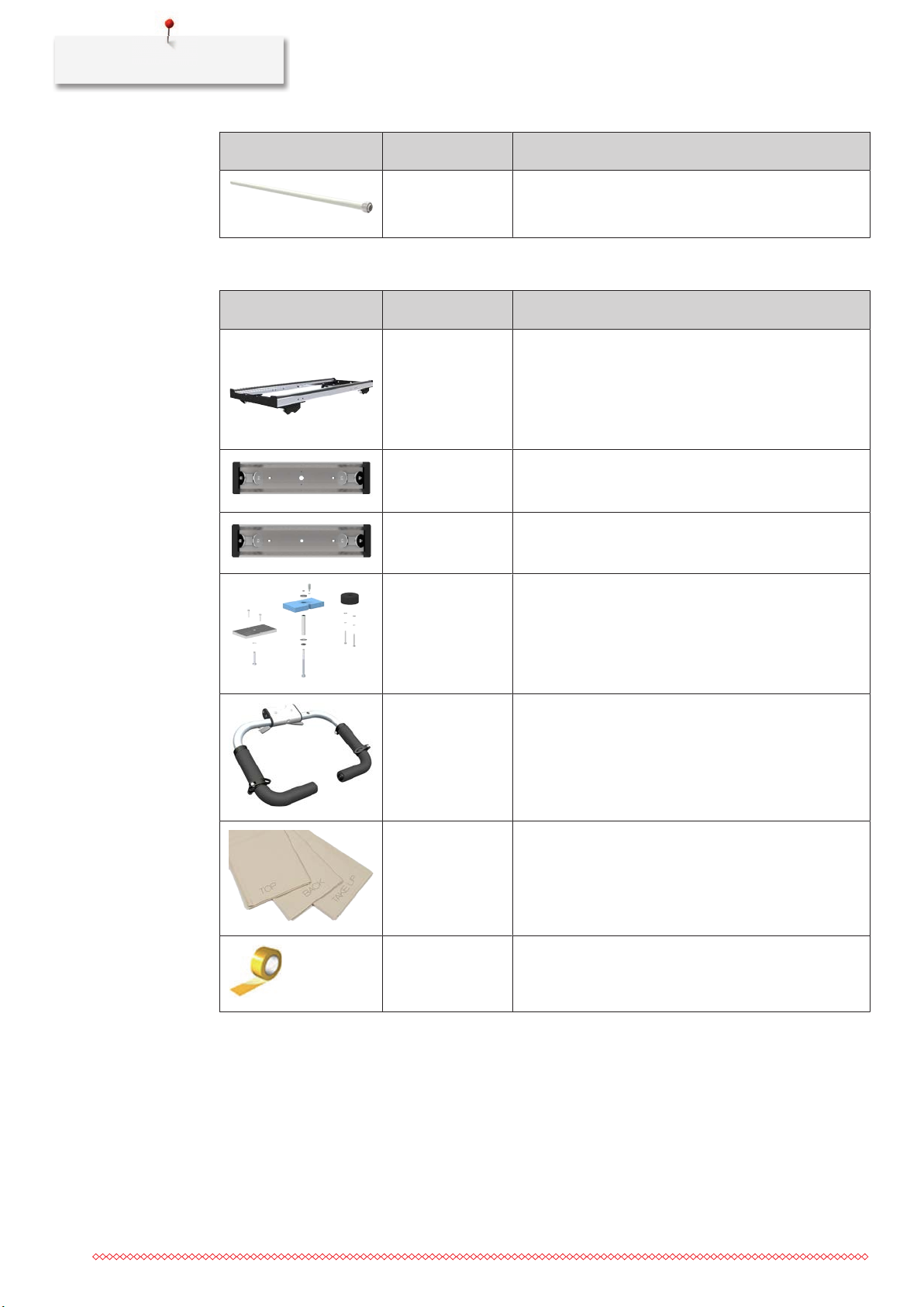
1.2 Overview of delivery ............................................... 7
2 Quilting frame assembly .................................... 12
2.1 Unpacking and checking the delivery ..................... 12
2.2 Adjusting the height .............................................. 12
2.3 Assembling the base frame (10-foot frame) ............ 14
Removing tracks ......................................................... 14
Fitting tabletops .......................................................... 14
Installing braces .......................................................... 15
Fitting the tracks ......................................................... 17
2.4 Assembling the base frame (5-foot frame) .............. 18
Removing tracks ......................................................... 18
Fitting tabletop ........................................................... 18
Installing braces .......................................................... 19
Fitting the tracks ......................................................... 20
2.5 Assembling the rail support unit ............................. 21
2.6 Connecting rails (10-foot frame only) ..................... 22
2.7 Fitting the top rail .................................................. 23
2.8 Fitting the backing rail ............................................ 24
2.9 Assembling the machine ........................................ 25
Attaching stand profiles .............................................. 25
Placing the machine .................................................... 29
2.10 Fitting the idler rail ................................................. 30
2.11 Fitting the Take-up rail ........................................... 31
2.12 Attaching the leaders ............................................. 32
2.13 Setting up the quilting area .................................... 34
2.14 Attaching the bungee cords ................................... 38
2.15 Leveling the Studio Frame ...................................... 38
2.16 Attaching the front handles ................................... 40
3 Technical specifications ...................................... 42
3.1 Dimensions ............................................................ 42

Important safety instructions
4
IMPORTANT SAFETY INSTRUCTIONS
Please observe the following general safety instructions when assembling the
quilting frame. Before using the quilting frame, also read the operating
instructions for the machine carefully.
WARNING
To protect persons from injuries:
• The packaging of the quilting frame and the machine is large and heavy. The
packaging should therefore always be carried by at least two adults
together.
• Position the packaging and individual parts so that they cannot fall over.
• Setting up the quilting frame requires at least two adults.
• During assembly of the individual and small parts, ensure that the parts are
kept out of the reach of small children (risk of suffocation).
• During assembly, ensure that your fingers do not get trapped or caught.
• Only use the quilting frame for the purpose described in these assembly
instructions.
• Do not use the quilting frame as a toy.
• The quilting frame can be assembled by children over the age of 8, as well
as by persons with reduced physical, sensory, or mental capacities or with a
lack of experience and knowledge, as long as they are supervised or have
been made aware of the potential hazards.
• Only use the accessories recommended by the manufacturer.
• Do not insert any objects into the openings on the quilting frame.
• Keep fingers away from all moving parts. Special caution is required in the
area of the take-up rail, top rail and backing rail, as well as the carriage.

Important information
5
Important information
Availability of the instruction manual
The manual forms part of the product.
• Store the Manual in a suitable location near the product and keep it available to consult.
• If the product is passed on to third parties, always include the Manual with the product.
• The latest version of the assembly instructions can be downloaded at www.bernina.com.
Proper use
The quilting frame serves as a support for the machines in the Q series and as a workplace for long arm
quilting. Any other use is not considered proper. BERNINA assumes no liability concerning consequences
resulting from an improper use.
Environmental Protection
BERNINA International AG is committed to environmental protection. We make every effort to increase the
environmental friendliness of our products by continually improving their design and production technology.
If the product is no longer required, disassemble all components and dispose of them in an environmentally
friendly way in accordance with the national guidelines. Do not dispose of it in household waste.
Explanation of symbols
DANGER Designates a high-risk hazard which can lead to serious injuries or potentially even death if not avoided.
WARNING Designates a medium-risk hazard which can lead to serious injuries if not avoided.
CAUTION Designates a low-risk hazard which can lead to minor or moderate injuries if not avoided.
NOTICE Designates a hazard which can lead to material damage if not avoided.
Tips from BERNINA quilt experts can be found next to this symbol.

My BERNINA
6
1 My BERNINA
1.1 Overview of the Studio Frame
The BERNINA Studio Frame is available in two versions: 5-foot frame and 10-foot frame.
These assembly instructions describe the assembly of both versions. The pictures in these assembly
instructions show the assembly of the 10-foot frame. Unless otherwise stated, these pictures apply equally to
the 5-foot frame. Differing assembly steps are indicated by the note "5-foot frame only" or "10-foot frame
only".
1
2
3
4
56
7
89
11
12
13
15
14
10
1 Leg, left 9 Handwheel
2 Leg, center (10-foot frame only) 10 Ratchet wheel, Take-up rail
3 Tabletop, left (10-foot frame only) 11 Ratchet wheel, backing rail
4 Top rail 12 Rail support, right
5 Rail support, left 13 Ratchet wheel, Top rail
6 Backing rail 14 Tabletop, right
7 Idler rail 15 Leg, right
8 Take-up rail

My BERNINA
7
1.2 Overview of delivery
The BERNINA Studio Frame is delivered in 4 boxes. Boxes 1–3 contain all the parts needed to build up a 5-
foot frame. Box 4 contains additional parts for expanding to a 10-foot frame. The machine is delivered in a
separate box.
Cardboard box Content
1 Legs, rail supports, tools and screws, small parts
2 Tabletop (5foot) and rails
3 Carriage and accessories
4 Center leg, tabletop (5foot), rails, screws and small parts
Box 1 – Parts for 5-foot frame
Illustration Number Designation
1 Leg, left
1 Leg, right
1 Rail support, left
1 Rail support, right
1 Rail support, left

My BERNINA
8
Illustration Number Designation
1 Rail support, right
1 Brace, front left
1 Brace, front right
1 Brace, back left
1 Brace, back right
3 Cover cap for rail end, right
1 Cover cap for take-up rail
1 Handwheel for take-up rail

My BERNINA
9
Illustration Number Designation
4 Cover cap for rail end, left
4 Bungee cord
4 Cord clamp
42 Screws, M8×1616 mm (16 pre-assembled)
12 Screws M4×20mm
12 Washers, M8 (12 pre-assembled)
5 Allen keys
1 Allen key with handle, 4mm
2 Open-end wrench 10–13 / 14–17
Box 2 – Parts for 5-foot frame
Illustration Number Designation
1 Tabletop, pre-assembled
1 Idler rail for 5-foot frame

My BERNINA
10
Illustration Number Designation
3 Backing-rail, top rail, take-up rail for 5-foot frame
Box 3 – Accessories
Illustration Number Designation
1 Carriage
1 Stand profile, front, for machine
1 Stand profile, rear, for machine
1 Vibration kit
1 Handles
3 Leaders
1 Adhesive tape, for attaching the leaders

My BERNINA
11
Box 4 – Parts for 10-foot frame
Abbildung Number Bezeichnung
1 Leg, center
1 Tabletop, pre-assembled
1 Brace, front, center
1 Brace, rear center
4 Rail extension for 10-foot frame
4 Rail coupler
2 Track coupler, incl. 8 grup screws
4 Plastic insert for 10-foot frame
18 Screws M8×16mm

Quilting frame assembly
12
2 Quilting frame assembly
2.1 Unpacking and checking the delivery
> Open the packaging and unpack the individual parts.
> Check the individual parts for damage.
> Check that the delivery is complete.
> If parts are missing or if you have any questions about the assembly, contact your specialist BERNINA dealer immediately.
2.2 Adjusting the height
The correct working height corresponds with the distance between the elbow and the floor.
Distance elbow-floor X in inch (cm) Setting holes
X
44 (112) 9
9
1
43 (109) 8
42 (106,5) 7
41 (104) 6
40 (101,5) 5
39 (99) 4
38 (96,5) 3
37 (94,0) 2
36 (91,5) 1
Required parts:
10-foot frame:
5-foot frame
Required tools:
• Allen key, 4mm
• Allen key, 5mm
• Open-end wrench

Quilting frame assembly
13
1
> Fix nut with open-end wrench and loosen screw with Allen
key (5 mm).
2
> Set all legs to the same length.
3
> Fix nut with open-end wrench and tighten screw with Allen
key (5 mm).
4
> Tighten the locking screw with an Allen key (4mm).
Preparing allignment of the Studio Frame
All legs are equipped with height-adjustable feet. These are designed only for horizontal alignment of the quilting frame.
Required tools:
• Open-end wrench, 17mm
1
> Loosen the locknut on all legs.

Quilting frame assembly
14
2.3 Assembling the base frame (10-foot frame)
Removing tracks
Required parts: Required tools:
• Allen key with handle, 4mm
1
> Remove 8 screws (M6 × 6 mm) from both table tops and
set aside.
2
> Remove the 2 tracks.
> Remove the 4 plastic inserts.
Fitting tabletops
Required parts: Required tools:
• Allen key, 5mm
• 12 screws
Notice: Assemble tabletops with the help of another person.
1
> Place the tabletop on the 2 supports of the right leg.
> Insert 2 screws from below but leave them loose.
2
> Place the tabletop on the supports of the center leg.
> Insert 4 screws from below but leave them loose.

Quilting frame assembly
15
3
> Place second tabletop on the support of the center leg.
Make sure that there is no space between the tabletops.
> Insert 4 screws from below but leave them loose.
4
> Place the tabletop on the 2 supports of the left leg.
> Insert 2 screws from below but leave them loose.
Installing braces
Required parts:
B
A
C D
E
F
Required tools:
• Allen key, 5mm
• 28 screws M8 × 16 mm
1
> Position the front left brace (A).
> Insert all 4 screws.
2
> Position the rear left brace (B).
> Insert all 5 screws.

Quilting frame assembly
16
3
> Position the rear center brace (C).
> Insert all 6 screws.
4
> Position the rear right brace (D).
> Insert all 5 screws.
5
> Position the front right brace (E).
> Insert all 4 screws.
6
> Position the front center brace (F).
> Insert all 4 screws.
7
> Check that all legs are at a 90° angle to the tabletop.
If the angles are not correct, align the legs.
> Tighten all screws on all braces.
> Tighten all 12 screws of the legs.

Quilting frame assembly
17
Fitting the tracks
Required parts:
4x
2x 4x
Required tools:
• Allen key with handle, 4mm
• Allen key, 3mm
• 8 grub screws, M6×6mm
• 16 screws, M6×6mm (see page14)
1
> Insert the coupling piece halfway into the track.
> Insert and tighten 2 grub screws (M6 × 6 mm).
2
> Push the track over the coupling piece as far as it will go.
3
> Insert and tighten 2 grub screws (M6 × 6 mm).
4
> Slide 2 plastic inserts (10 ft) into each of the tracks.
5
!
> Place both tracks onto the table top with the wide edge
facing inwards and push them outwards until they are flush
with the edge of the table.
6
> Insert 8 screws (M6 × 6 mm) at the front and rear.
> Check that the rear track is flush with the rear edge of the
table. Tighten all rear screws.
> Do not tighten the front screws yet. It must still be possible
to move the front track.

Quilting frame assembly
18
7
> Place the carriage and move it back and forth a few times
from the far left to the far right.
– The front track adapts exactly to the wheel distance of
the carriage.
8
> Slide the carriage from the left edge to the right edge of
the frame, pressing the carriage onto the tracks at the
location of each screw.
> Tighten the screw from below.
2.4 Assembling the base frame (5-foot frame)
Removing tracks
Required parts: Required tools:
• Allen key with handle, 4mm
1
> Remove 8 screws (M6 × 6 mm) and set aside.
2
> Renove the 2 tracks.
Fitting tabletop
Required parts: Required tools:
• Allen key, 5mm
• 4 screws, M8×16mm
Notice: Assemble tabletop with the help of another person.

Quilting frame assembly
19
1
> Place the tabletop on the 2 supports of the right leg.
> Insert 2 screws from below but leave them loose.
2
> Place the tabletop on the 2 supports of the left leg.
> Insert 2 screws from below but leave them loose.
Installing braces
Required parts:
A
B C
D
Required tools:
• Allen key, 5mm
• 18 screws, M8×16mm
1
> Position the front left brace (A).
> Insert all 4 screws.
2
> Position the rear left brace (B).
> Insert all 5 screws.

Quilting frame assembly
20
3
> Position the rear right brace (C).
> Insert all 5 screws.
4
> Position the front right brace (D).
> Insert all 4 screws.
5
> Check that all legs are at a 90° angle to the tabletop.
If the angles are not correct, align the legs.
> Tighten all screws on all braces.
> Tighten all 4 screws of the legs.
Fitting the tracks
Required parts:
2x
4x
Required tools:
• Allen key with handle, 4mm
• 8 screws, M6×6mm (see page18)
Table of contents
Other Bernina Industrial Equipment manuals
Popular Industrial Equipment manuals by other brands

YoraHome
YoraHome 6550 user manual

NOZAG
NOZAG NSE S Series Assembly and operating manual

Hanskamp
Hanskamp MultiDos 035-000-000 Series Installation and operating instructions

CIMLINE
CIMLINE 105 Owner's/operator's manual

Premier
Premier 690L Installation, Inspection, Operation & Maintenance Guide

Ortlinghaus
Ortlinghaus 0086-237 Series Translation of original operating manual