BERTHOLD TECHNOLOGIES LB4710-050 User manual
Process Control
Limit Switch
Mini-Switch LB 471
Hardware Manual
ID No. 39505 BA2
Rev. No.: 03 17. Nov. 2015
Soft. Version: 1.12 or higher
detect and identify
User’s Guide


The units supplied should not be repaired by anyone other than Berthold Service en-
gineers or technicians by Berthold.
In case of operation trouble, please address to our central service department.
The complete user’s guide consists of two manuals, the hardware de-
scription and the software description.
The hardware manual comprises:
mechanical components
assembly
electrical installation
radiation protection guidelines
technical data
electrical and mechanical drawings
The software manual comprises:
operation of the evaluation unit
parameter description
basic setting
calibration
error messages
The present manual is the hardware description.
Subject to change in the course of further technical development.


Table of Contents
Mini-Switch LB 471
5
Table of Contents
Page
Chapter 1. General Information 9
1.1 Use and Function 9
1.2 Target Group 9
1.3 Radiation Protection Courses 10
1.4 Definitions 10
1.5 Safekeeping of the User’s Guide 12
Chapter 2. Safety 13
2.1 Safety Concept 13
2.2 Symbols and Pictograms 13
2.3 Radiological Safety Officer 14
2.4 Duty of Notification 14
2.5 Radiation Protection Areas 15
2.5.1 Exclusion Areas 15
2.5.2 Controlled Areas 15
2.5.3 Monitoring Areas 16
2.6 Safety Installations 17
2.6.1 Source Shieldings 17
2.7 General Safety Instructions 19
2.8 Emergency Instructions 19
2.8.1 Theft Protection 20
Chapter 3. Functional Safety 21
3.1 Use and Function 21
3.2 Safety Function 22
3.3 Safety Requirement 22
3.4 Project Planning 22
3.5 Getting Started 24
3.6 Behavior during Operation and Malfunctions 28
3.7 Recurrent Performance Test 29
3.8 Safety-Technical Data 29
Chapter 4. Instrument Description 36
4.1 Function 36
4.2 Mini Switch LB 471 Versions 37
4.2.1 Type Code 39
4.3 Detectors 40
4.3.1 GM Detector 40
4.3.2 NaI Detector 41
4.3.3 Super-Sens Detector 43
Chapter 5. Installation 45
5.1 Transport to the Installation Site 45
5.1.1 Transporting Detector and Evaluation Unit 45
5.1.2 Transport Shielding with Source 45

Table of Contents
Mini-Switch LB 471
6
5.1.3 Temporary Storage of Sources 46
5.1.4 Installation Site 46
5.1.5 Unpacking and Cleaning System Parts 46
5.2 Installing the Detector 47
5.2.1 Fastening Clamps for GM Detectors and NaI Counters 48
5.2.2 Stainless Steel Detector Holder (Alternative) 48
5.2.3 Installation of the GM Detector 49
5.2.4 Installation of the GM Detector 51
5.2.5 Installation of Super-Sens with Axial Irradiation 54
5.2.6 Installation of Super-Sens with Radial Irradiation 56
Chapter 6. Water Cooling 59
6.1 Subsequent Installation of Water Cooling (Option) 61
6.1.1 Water Cooling for NaI Detector with Collimator 62
6.1.2 Water Cooling for NaI Detector with Collimator 64
6.1.3 Water Cooling for GM Detector 65
6.2 Amount of Cooling Water Required 66
Chapter 7. Shielding Installation 67
7.1 General Installation Instructions 67
7.2 Installation Proposal for Shielding 68
7.3 Pneumatic Shielding Shutter (Option) 70
Chapter 8. Electrical Installation 71
8.1 Connecting Evaluation Unit and Detector 72
8.1.1 Pin Assignment of Terminal Block 73
8.1.2 Installing NaI Detector or Super-Sens 74
8.1.3 Installing the GM Detector 75
8.2 Digital In-/Outputs 77
8.2.1 Relays 77
8.2.2 Digital Input 77
8.3 Connecting the Evaluation Unit to Power 78
Chapter 9. Maintenance 79
9.1 Malfunctions 79
9.2 Replacing Fuses 79
9.3 Replacing the Evaluation Unit 80
9.4 Repairing the Detector 80
9.4.1 Dismantling the NaI Detector 81
9.4.2 Checking the Crystal-Multiplier Combination 84
9.4.3 Assembly of Crystal-Multiplier Combination 85
9.4.4 Plateau Measurement 86
9.4.5 Dismantling the GM Detector 87
9.5 Replacing the Source 88
9.5.1 Replacing the Source 90
9.6 Customer’s Service 92
9.6.1 Sending in the Electronics 93
9.6.2 Sending in Source and Shielding 94

Table of Contents
Mini-Switch LB 471
7
Chapter 10. Servicing the Shielding 95
10.1Checking Shielding and Source 95
10.1.1 Testing the Locking Mechanism 95
10.2Leak Test 96
10.2.1 Leak Test Documentation 96
10.2.2 Performing a Wipe Test 97
Chapter 11. Radiation Protection 99
11.1Basics and Directives 99
11.2Radiation Dose Calculations 101
11.3Calculation with a given Dose Rate 101
11.4Activity-based Calculation 102
Chapter 12. Disposal 103
Chapter 13. Technical Data 105
13.1Evaluation Unit 105
13.2Detectors 106
13.3Shieldings 108
13.4Pneumatic Locking Drive 108
Chapter 14. Certificates 109
14.1ATEX Certificate for Evaluation Unit LB 4710-XXX 109
14.2ATEX Certificate NaI Detector 113
14.3ATEX Certificate GM Detector 117
14.4EC Declaration of Conformity 119
Chapter 15. Technical Drawings 121
15.1NaI Detector 121
15.2GM Detector 122
15.2.1 Fastening Clamps 123
15.2.2 Detector Holder for GM Detector and NaI Counter 124
15.3Super-Sens Detectors 125
15.4Point Source Shielding LB 744X 131
15.5Dimensions of the Evaluation Unit 134
15.5.1 19" Rack 134
15.5.2 Wall Housing 135
15.5.3 Cassette 136
15.6Connection Diagrams 137
15.6.1 19" Rack 137
15.6.2 Wall Housing 138
15.6.3 Cassette 139
15.6.4 Connection Diagram for Power Supply Unit in 19" Rack 140


Chapter 1 General Information
Mini-Switch LB 471
9
Chapter 1. General Information
1.1 Use and Function
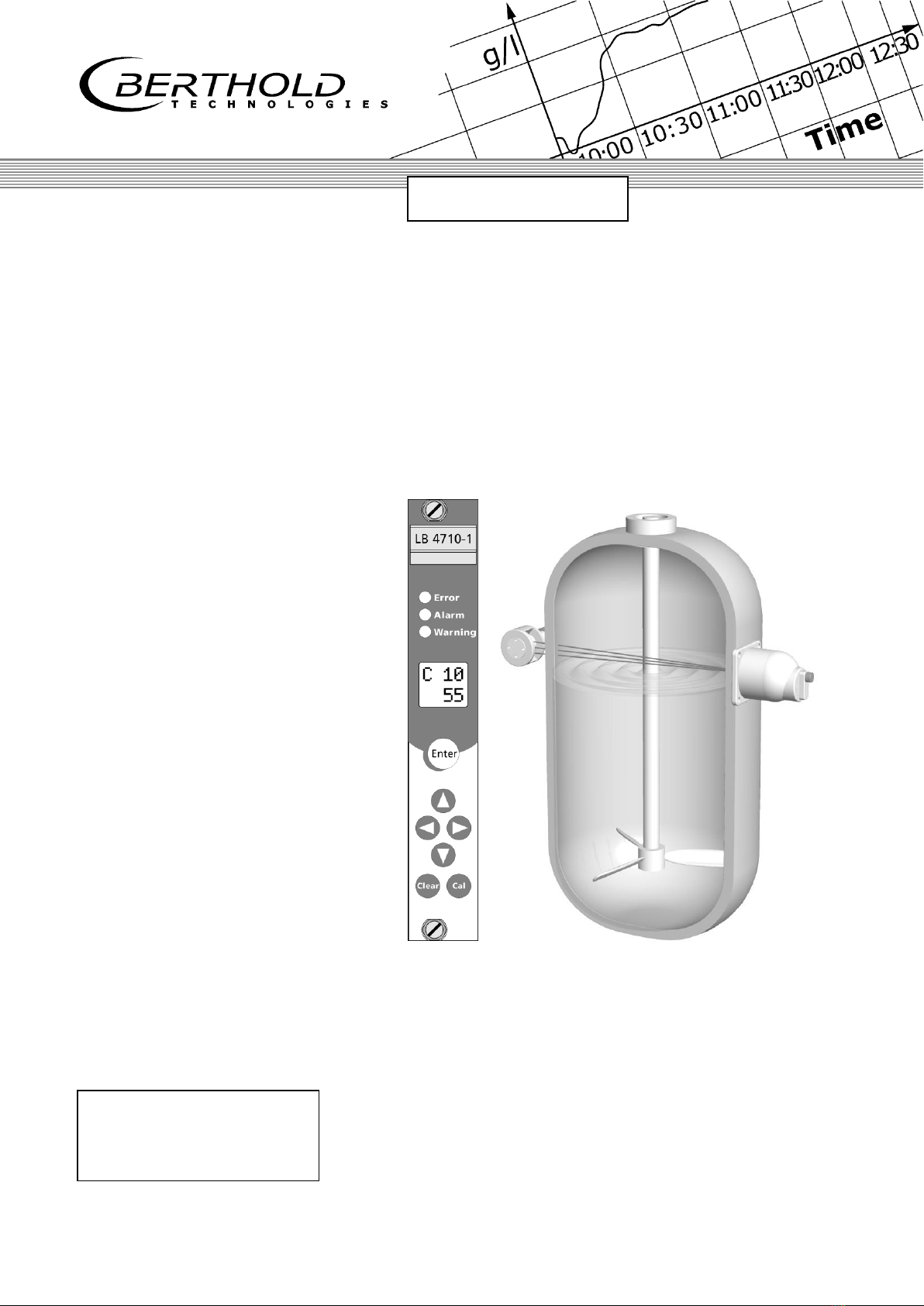
The limit switch system LB 471 Mini Switch has been designed for
monitoring and detection of levels in containers and pipelines.
Licensed as an “overflow protection device for containers storing
liquids that are hazardous to waters”in accordance with the Water
Resources Act, the system may also be used as overflow protec-
tion device.
Beyond this scope, each application is considered as not being in
compliance with the law and may result in severe personal injury
or property damage.
BERTHOLD TECHNOLOGIES does not assume any liability for this kind
of injuries or damage.
1.2 Target Group
This user’s guide has been written for operating, assembly and
service personnel.
The system may only be assembled, serviced and maintained by
authorized and trained persons. Any modification of the settings
may only be carried out by persons who are familiar with the func-
tion of the system. Persons working with ionizing radiation must be
familiar with the rules of radiation protection and adequate work
techniques.
Personnel have to be specially trained and informed about possible
hazards. Detailed knowledge of this user’s guide and careful ob-
servation of the instructions contained therein is an essential pre-
requisite.
Each staff member has to know the major rule of the “ALARA prin-
ciple”(as low as reasonably achievable).
BERTHOLD TECHNOLOGIES is offering appropriate training courses.
Depending on the participant’s professional qualifications, two
kinds of training can be chosen:
Qualification
Training

Chapter 1 General Information
Mini-Switch LB 471
10
1.3 Radiation Protection Courses
Special course in radiation protection
(Duration: 2 days)
This course is needed if the participant has not yet received any
radiation protection training. A successfully completed course
has a validity of 5 years.
Refreshing course in radiation protection
(Duration: 1 day)
All persons who have already successfully completed the spe-
cial course may refresh their special knowledge with this course
(Radiation Protection Ordinance of August 1, 2001).
A successfully refreshing course has a validity of 5 years.
1.4 Definitions
Automatic
Some parameters can either be set to the automatic or manual
mode. In the automatic mode the value is calculated using a
formula. Enter -1 to enable the automatic mode. The inverted C
in the top row indicates whether a parameter has been set to
automatic.
EVU
Evaluation Unit
Edit
Change value
Edit mode
In this mode, a value can be changed. Not every parameter can
be changed since some parameters are only used as display
values. Editable Parameters can be set to the edit mode with
the “Enter”button. In the edit mode the cursor positioned over
a digit is flashing.
GM detector
Detector with Geiger-Müller counter tube
NaI detector
NaI = sodium iodine crystal = scintillator
Scintillation detectors are very sensitive to Gamma radiation.
See pages 40 and 121.
Super-Sens detector
Detector which is highly sensitive to Gamma radiation with
large-volume plastic scintillator 150x150mm
See pages 43 and 125.
Limit value
Count rate or percentage value upon reaching the measure-
ment level

Chapter 1 General Information
Mini-Switch LB 471
11
HV
Detector high voltage
Cassette
Case (7 TE) into which the evaluation unit LB 4710 is installed,
so it can be used in any 19" rack
Empty
Level below limit value.
Empty count rate
Count rate with empty container
Manual
Some parameters can either be set to the automatic or manual
mode. For the manual mode you have to enter a fixed value in
the respective parameters.
Nuclide / Isotope
Type of radiation source: Cobalt-60 (Co-60) or Cesium-137
(Cs-137) for level measurements.
Zero count rate
Count rate caused by natural environmental radiation.
Parameters
A value stored under a certain code.
Timeout
Time after which an automatic reset is performed.
Full
Level below limit value.
Full count rate
Count rate with full container.
Count rate
Value of counts relative to one second.
cps
Count rate unit: Counts per second.
Read in count rate
A process that is started by the user in order to determine the
average value of the count rate at the respective level. This
count rate is needed to calibrate the measurement. The count
rate is averaged over a certain time (standard 60 s) to exclude
statistical and process-immanent fluctuations.
Factory setting
All parameters have been preset by the manufacturer using
standard values. In most cases this simplifies calibration of the
instrument significantly. Despite factory setting, calibration al-
ways has to be performed.
mSv
Dose rate unit
Millisievert

Chapter 1 General Information
Mini-Switch LB 471
12
MBq
Mega-Becquerel
This unit indicates the source activity. Each Bq corresponds to
one decay per second..
1 MBq = one million decays
mCi
Milli-Curie
This unit is also used for the activity of a source. However, this
unit has been replaced by the unit MBq (1mCi = 37 MBq)
1.5 Safekeeping of the User’s Guide
Note!
This user’s guide always has to be available at a fixed place. The
personnel have to be informed about this place. Any time the de-
vice is used by another operator and whenever there is a change
in ownership of the device, the user’s guide has to be given to the
new operator or owner.

Chapter 2 Safety
Mini-Switch LB 471
13
Chapter 2. Safety
2.1 Safety Concept
The state-of-the-art system is designed in accordance with accept-
ed safety rules to ensure the greatest possible on-the-job safety.
To rule out health hazards when handling radioactive substances,
limit values stating the highest acceptable radiation exposure of
the operating personnel have been defined on an international lev-
el. These limits have to be observed when designing shieldings and
planning the configuration of the measuring system at the meas-
urement point.
2.2 Symbols and Pictograms
The following symbols identify safety instructions in this user’s
guide:
Danger!
Possible danger for life and health hazard
Caution!
Possible hazard
Minor personal injuries
Warning!
Possible hazard
Property damages
Note!
Tips for application and useful information
The safety instructions are supplemented by explanatory picto-
grams, for example:

Chapter 2 Safety
Mini-Switch LB 471
14
2.3 Radiological Safety Officer
To ensure proper handling and the observance of the statutory
requirements the operating company has to appoint a radiological
safety officer who is in charge of all radiation protection issues in
connection with the measuring system.
The radiological safety officer has to:
monitor working with the radiometric measuring system
draw up a plan for the organization of radiation protection
monitor compliance with the regulations of the Radiation Pro-
tection Ordinance
issue directives and carry out training and instruction of the
employees
get on-site information on the situation and takes appropriate
actions immediately if operation problems have occurred
cooperates with the work’s council or the personnel office and
qualified personnel for on-the-job safety, advises and informs
them on important radiation protection issues.
2.4 Duty of Notification
Caution!
Radioactivity!
In case of suspected damage to the shielding, the radiological
safety officer has to be informed immediately. Further steps can
be taken in consultation with BERTHOLD TECHNOLOGIES.

Chapter 2 Safety
Mini-Switch LB 471
15
2.5 Radiation Protection Areas
Radiation protection areas define the boundaries around a radia-
tion source. The maximum dose rate defines the limit. We distin-
guish three radiation protection areas:
2.5.1 Exclusion Areas
Exclusion areas are areas in which the local dose rate may be ex-
ceed 3 Millisievert (mSv) per hour. These areas have to be pro-
tected such that nobody has unchecked access to these areas –
not even with single body parts. Actually, these areas can occur
only in the active beam in the direct vicinity of the shielding.
Caution!
Radioactivity!
The radiation protection directives have to be observed.
Exclusion areas have to be protected such that nobody has un-
checked access to these areas –not even with single body parts.
This has to be ensured through constructive measures, for exam-
ple by protective covers.
2.5.2 Controlled Areas
Controlled areas are areas in which persons in one calendar year
may receive an effective dose of more than 6 mSv if they stay in
this area 40 hours a week and 50 weeks per calendar year. Based
on this, the calculated maximum dose rate is 3 µSv/h. These areas
should be planned such that accessibility is virtually not possible or
that the required safety fences can be installed easily. If con-
trolled areas are accessible they have to be secured. Moreo-
ver, they have to be identified clearly and permanently by a radia-
tion danger sign and the comment “Controlled Area”. Persons may
access controlled areas only to carry out maintenance work for the
operations going on inside this area (§ 37). Body doses have to be
calculated or personal doses have to be measured. The authorities
may permit exceptions from the demarcation and identification
duty, provided individuals or the general population are not en-
dangered. Higher limit values are admissible if reliable in-
formation is provided that the person affected stays within
the controlled area for a shorter period of time.

Chapter 2 Safety
Mini-Switch LB 471
16
Caution!
Radioactivity!
The radiation protection directives have to be observed.
Controlled areas outside the shielding have to be identified and
secured if they are accessible.
2.5.3 Monitoring Areas
Monitoring areas are operation areas which do not belong to the
controlled area. In these areas, a person may receive an effective
dose of more than 1 mSv in one calendar year.
The monitoring area starts at the controlled area. It is an area in
which persons staying permanently in this area may be exposed to
a radiation level of more than 1 mSv in one calendar year. For a
stay of 40 hours per week and 50 weeks per year the area is be-
tween the dose rate limit values of 3 µSv/h and 0.5 µSv/h. It has
to be ensured that persons are not exposed to a dose exceeding
1 mSv per year, taking into account the actual time they stay in
this area. This means that no permanent work place may be set up
in this area.
Chapter 2 Safety
Mini-Switch LB 471
17
2.6 Safety Installations
2.6.1 Source Shieldings
Caution!
Radioactivity!
The shielding with the source installed may be taken into opera-
tion by specially licensed persons who have been trained on han-
dling radioactive materials only after consultation and coordination
with the radiological safety officer.
The radiation exit channel must only be opened by authorized per-
sons after consultation with the radiological safety officer.
Modification of or tampering with the shielding construction are
prohibited.
Co-60 or Cs-137 point sources are used for the system. They
are tightly welded into a sturdy stainless steel capsule, so that the
radioactive substance cannot escape and contamination is pre-
vented. The capsule with the source is fixed on a holder and
installed into the shielding.
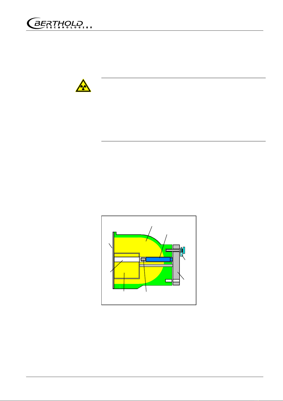
The shielding consists of a lead cylinder with radiation exit channel
, surrounded by a steel jacket. The locking core is fixed to a
lever . The padlock secures the open / closed position and
protects the source against unauthorized removal.
Shielding
Locking core
Radiation channel
Point sources
Source holder
Lever
Padlock
Cover plate front
When turning the lever , the locking core is rotated as well and
the radiation exit channel is opened towards the detector. The ar-
row on the lever is pointing towards “OPEN”.
Source
Shielding
Figure 1:
Point source shielding
radiation channel open
Sectional drawing

Chapter 2 Safety
Mini-Switch LB 471
18
Lever with arrow
Padlock
Cover plate rear
The radiation exit channel has to be closed during transport, as-
sembly and while carrying out work on the container.
The arrow on the lever is then pointing to “CLOSED”.
The lever or the locking core is secured by a padlock in the
“OPEN”and in the “CLOSED”position.
Shielding, radiation type, isotope and activity have to be selected
for each measuring configuration such that the internationally
permissible dose rate limits will not be exceeded.
The source and shielding version is documented in the supplied
technical source documentation and on the type label on the
shielding.
Source number
Activity
Isotope
Source manufacturing
date
Dose rate in
1m distance
Effective shielding
thickness
Shielding material
Type of shielding
Shielding manufacturer
Figure 2:
Shielding
- view of lock
Type label
Figure 3:
Type label
on shielding
Strahler-Nr.: 1234 - 11- 94
MBq Co-60
400
Abschirmung
mm
Datum 12.11.94
Pb
98
Dosisleistung in 1m Abstand
5Sv/h MODEL LB7440
Bad WildbadD-75323

Chapter 2 Safety
Mini-Switch LB 471
19
2.7 General Safety Instructions
Caution!
The safety instructions in this user’s guide have to be observed
without fail.
All laws, directives, accident prevention regulations and generally
accepted safety regulations have to be complied with!
The system may be used only in technically good order and only
for contractual use!
Only persons may work with the system who have been author-
ized to do this and who have the proper qualification and have
received the necessary instructions!
Installations and modifications on the system which may affect the
operational safety are prohibited!
2.8 Emergency Instructions
The following basic principles are indispensable for health and
safety: Time, distance and shielding. In an emergency, the follow-
ing provisions have to be taken:
Danger!
Hazard due to radiation damages.
Never touch the source with your hands!
Restrict access to this area, identify radiation protection areas.
Check the function of the shielding and measure the dose rate.
Localize the source.
Document the event and, if possible, estimate the potential
radiation exposure of the persons involved.
Report event to BERTHOLD TECHNOLOGIES.
In case of loss of radiation sources, the regulatory agency has
to be notified immediately.
In case of suspected damage to the source capsule the follow-
ing issues have to be taken into consideration:
Grasp source with a tool (e.g. a pair of pliers or tweezers) and
put both (source and tool) into a plastic bag.
Place plastic bag behind an auxiliary shielding (concrete wall,
steel or lead plate).
Check if environment is free of contamination.
If a source has any leaks or if you suspect that the permissible
dose has been exceeded, the regulatory agency has to be noti-
fied immediately.

Chapter 2 Safety
Mini-Switch LB 471
20
2.8.1 Theft Protection
Radioactive substances or facilities containing radioactive sub-
stances have to be secured such that they are protected against
access by unauthorized persons. If you discover that radioactive
substances are missing, you have to notify the radiological safety
officer and the regulatory agency. In case of theft, the police have
to be informed.
Please see Chapter 11 for more information on radiation protection.
This manual suits for next models
7
Table of contents
Popular Switch manuals by other brands


Enterasys
Enterasys Matrix 2G4072-52 Configuration guide

pro bel
pro bel Freeway Series user guide

SICK
SICK i16S operating instructions

Signature Hardware
Signature Hardware AIR SWITCH 948127 quick start guide

Intel
Intel EXPRESS 330T quick start guide

Eterna
Eterna WS120PIR Safety and installation instructions


