manuals.online logo
Brands
  1. Home
  2. •
  3. Brands
  4. •
  5. Kverneland
  6. •
  7. Farm Equipment
  8. •
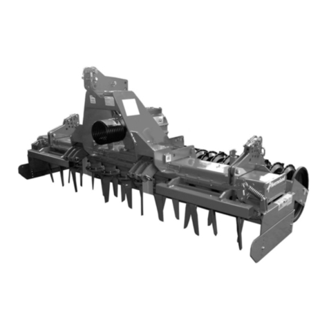
  9. Kverneland H Series Operating manual

Kverneland H Series Operating manual

1
1
Date: 01.01.2017
Machine type: Power Harrow H series 3-4m
Address: Kverneland Group Soest GmbH.
Coesterweg 42
59494 Soest
Germany
Receiver: Technical Service
Details: Technical machine information, adjustments and failure finding
Serial number: > serial number ACPOHxx……..
Technical Service Manual Power Harrow H series 3 - 4m
2
Content
2
General data and equipment…….............................3
−Road transport
−Working position
−Construction
−Rollers options
−Leveling bar regulation
Gearboxes …………………………………….……..17
−Central gearbox disassembly
−Central gearbox assembly
−Central gearbox technical specifications
−Lateral gearbox disassembly
−Lateral gearbox assembly
−Lateral gearbox technical specifications
Basic hydraulic circuit (std. equipment)…...........…31
−Distributor Block
−Roller sequence circuit
−Folding circuit
−Transport Lock circuit
−Roller Lift circuit
−Line Marker circuit (optional)
Electric-hydraulic functions (optional)………......…38
−Folding-transport lock function
−Roller lift-roller sequence function
−Roller lift function
Circuit with Control panel……………………………42
−Central gearbox
−Side gearbox
−Drivelines
3
3
NG-S 101 – General data and equipment
Specifications NG-S 401 NG-S 451 NG-S 501 NG-S 601
Transport width 2,90 m
Transport length with roller 1,65 m
Working length with roller 1,73 m
Working hight 1,5 m
Transport hight 2,11 m 2,35 m 2,6 m 3,1 m
Working speed 4-8 Km/h
Transport speed 40-45 Km/h
Working width 4 m 4,5 m 5 m 6 m
Number of rotor 16 18 20 24
Tines 32 36 40 48
Weight with packer roller 2800 Kg 3050 Kg 3500 Kg 3900 Kg
Weight with cracker roller 3000 Kg 3200 kg 3730 Kg 4170 Kg
Center of gravity 0, 7 m
PTO speed 1000 rpm
Max power 257 hp
Min power 132 hp
Overload protection on lateral drives 2,5 kN
Rotor speed 246,326,387 rpm + neutral position
4
General data and equipment
4
3100 mm
1650 mm 2900 mm
Road transport
• Total weight : 3,900 kg • Rear view
5
5
General data and equipment
Road transport
3100 mm
1650 mm
• Total weight : 3,900 kg
6
6
• Rear view • Front view
Road transport
General data and equipment
2900 mm
3100 mm
7
General data and equipment
• Total weight : 3,900 kg
7
Working position
8
8
• Rear view
• Front view
General data and equipment
Working position
6000 mm
9
9
700 mm 1730 mm
1500 mm
Working position
• Total weight : 3,900 kg
General data and equipment
10
General data and equipment
Quick-fit tines
Construction
10
hydraulic roller adjustment
Track eradicator
Oil cooler
Lateral stone guards with spring
Lightning equipment rear
Cat.III - IV floating lower attachments
Safety shields
Front drive shaft guard
third-point attachment
jacks for machine closing
hydraulic distributors
hooks for locking the machine into closed position
Central gearbox with lever control
drive shaft hook
Spring track eradicator
Leveling bar
11
General data and equipment
Construction
11
Height of gears 50 mm
Conical bearing int. Ø 55mm
outer Ø 95mm
Welded shaft housing
No influence of vibrations
Distance of bearings 80 mm
midth - midth
Conical bearing int. Ø 60mm outer Ø
100mm
Double sealing with
fixing on tine holder
Ø of shaft 55/60 mm
high resistance
Distance bushing 50 mm
Trough 10mm
special profile
Self supporting
trough= no additional
frame is required
BOLT : Tighten it to 175 Nm
BOLT : assembled with Loctite 638
Tighten it to 150÷200 Nm
MA44000106 Ring Nut
•Assembled with Loctite 243
• Tighten it to 140-160 Nm
• Dent the top neck of the metal
ring-nut on two points
Shim adjustment
BOLT : assembled with Loctite 638
Tighten it to 350÷400 Nm
Seal with silicon
rubber Angst-
Pfister
Permabond
RTV1473
12
General data and equipment
0°
Construction
12
Timing process:
1. Remove all tine carriers.
2. Assemble one central tine carrier and rotate it so that the tines are in-line
with the axis of the trough (reference rotor).
3. Assemble the two adjacent tine carriers with a phase angle of between +5° and +15°.
Procedure: position the tine carrier at 90° to the reference tine carrier and rotate it until you find the first
possible assembly position. The phase angle must not exceed 15°. If it is not possible to find a
position between 5° and 15° rotate the tine carrier 180° and try again. NB The alignment of three adjacent
tine carriers must be convergent (or divergent), not parallel. (Fig.1)
4. Rotate the newly assembled tine carrier so that it is in-line with the trough (as in step 2)
5. Assemble the next adjacent tine carrier so that the phase angle is between -5° and -15° (as in step 3
but in the opposite direction). (Fig.2)
6. Proceed in this way for all remaining tine carriers.
-75°75°30°45°60° -30° -45 -60 -15
Resetting operation of tine carriers’ ” TIMING”,
13
General data and equipment
Construction
13
Lenght
Quantity
(liter)
for each
trough
400 13
450 16,5
500 19
600 23
Grease type
suggested Grease
features Brand
AGIP- GREASE EP 00 LITHIUM
grease EP
SHELL ALVANIA EP-LF
00 NLGI 00 G00K
DIN 51826
Generic Brand Lithium grease
SAE140EP
NLGI 00 G00K
DIN 51826
Att.on!!
We advice do not mix up
The Synthetic grease with
Mineral grease
14
General data and equipment
Construction
14
15
General data and equipment
Construction
15
IMPORTANT:
1° During the replacement of new central gearbox, please take care about lateral drive line
Attached you will find some info about, how to respect the phase on the lateral shafts during maintenance work.
2° Do not exchange parts of the left and right lateral driveline
The lateral driveline are identified by two different part numbers. Moreover on left driveline the identification number
brought back on the torque limit side.
16
General data and equipment
Rollers
16
Type of soil
Heavy
Tough
Medium
Sandy
Normal
condition All
conditions
Simplified
cultivation
techniques
Packer Roller Diam 600
Cage roller
Packer Roller Diam 600 or
Diam 500
Actipack roller
Flexline
roller
Cracker
roller
17
17
General data and equipment
Leveling bar equipment
18
Central gearbox 3 speed (Comer D-825 A)
18
MAGE59………………………
• - Disassembly ………………….
• - Assembly …………………….
• - Technical specifications ……
NOTES
•Warning : Disassembled shims if not damaged, must
to be assembled in the same positions.
19
1. Greabox Disassembly
19
•Plugs (32),(39),(47) and empty the oil
•Level warning light (67)
•Washer (66)
•Bolts (10)
•Molded cover (56)
•Bolts (10)
•Molded plate (58).
•Cover (57), using chisel and hammer.
•Locknut (54),take away bolt washer (55)
•External lever (49) disassemble
•Take away o-ring (48)
•Lever (59 from cover (57).
•Disassemble snap ring (61) and fork (60)
•Disassemble oil seals (36),(43)
•Unscrew bolts(45), disassemble cover(46)
•Disassemble:
•Stud bolts (41),shim (44) outer ring (42)
•Tools :Allen screw wrench n°9/16”,
Fork wrench n°1/2”-17-22-27-30,
Adjustable wrench, snap ring pliers.
•Disassemble the shaft (38), from side (A)
•Hit the crown wheel (26) from side (B)
•In order to extract inner bearing (42)
•Crown wheel (26) and shim (40)
•Disassemble:
Snap ring (24), inner ring (34)
snap ring (35), shims (37),outer ring (34)
• Uncaulk locknut (27).
• Unscrew locknut (27), disassemble
• Shim (28), crown wheel(64) and shim (25)
•Tools : Chisel, hammer, fork wrench n°17
Allen screw wrench n°4, snap ring pliers
Extractor, adjustable wrench
20
2. Disassembly
20
•Tools : Chisel, hammer, snap ring pliers,
Extractor, fork wrench n°17, adjustable wrench.
•Disassemble oil seals (4),(30)
•Disassemble snap ring (3), shim (6).
•Hit the shaft (29) from side (C)
•Pick up outer ring (5),disassemble inner ring
(5) from shaft (29), take away shim (2)
•Pick up from inside housing : Gear (7)
• Shim (1), spacer(16), gear(18),spacer(20)
• Gear (31),spacer (65) inner ring (5)
•Unscrew bolts (10), disassemble cover (9)
•Hit the shaft (19) from side (D) hole,
To reach the snap ring (24) from side (E)
•Take away inner ring (62).
•Disassemble snap ring (24) and shim (23)
•Uncaulk locknut (11), unscrew locknut (11).
•Tools : Extractor, snap ring pliers, chisel, hammer.
•Disassemble shaft (19), inner ring (12)
snap ring (8) and take away shim (13)
•Disassemble snap rings(52) spacers
(63), pistons 53) and spring(50)
•Take away gears (14),(18),(21)
•Disassemble bearings brass (15),(22)
using chisel paying attention not to
damage the brass surfaces.
•Disassemble outer rings (5), (12),(62)

This manual suits for next models

4

Other Kverneland Farm Equipment manuals
Kverneland a-drill User manual

Kverneland

Kverneland a-drill User manual

Kverneland NG-M 101 User manual

Kverneland

Kverneland NG-M 101 User manual

Kverneland Miniair Nova User manual

Kverneland

Kverneland Miniair Nova User manual

Kverneland CTC User manual

Kverneland

Kverneland CTC User manual

Kverneland 2620M User manual

Kverneland

Kverneland 2620M User manual

Kverneland NGH 301 User manual

Kverneland

Kverneland NGH 301 User manual

Kverneland ES User manual

Kverneland

Kverneland ES User manual

Kverneland CLC Evo Wings User manual

Kverneland

Kverneland CLC Evo Wings User manual

Kverneland BE User manual

Kverneland

Kverneland BE User manual

Kverneland Vicon PS225 User manual

Kverneland

Kverneland Vicon PS225 User manual

Kverneland 150 Series User manual

Kverneland

Kverneland 150 Series User manual

Kverneland 4328LT User manual

Kverneland

Kverneland 4328LT User manual

Kverneland CTC 427 User manual

Kverneland

Kverneland CTC 427 User manual

Kverneland CLC Evo User manual

Kverneland

Kverneland CLC Evo User manual

Kverneland Vicon Andex 724 User manual

Kverneland

Kverneland Vicon Andex 724 User manual

Kverneland Vicon Andex 353 User manual

Kverneland

Kverneland Vicon Andex 353 User manual

Kverneland 2316M Operating manual

Kverneland

Kverneland 2316M Operating manual
Kverneland CLG-II-CLC TINES User manual

Kverneland

Kverneland CLG-II-CLC TINES User manual

Kverneland 41-L Series User manual

Kverneland

Kverneland 41-L Series User manual

Kverneland CLG-II User manual

Kverneland

Kverneland CLG-II User manual

Kverneland TS-T User manual

Kverneland

Kverneland TS-T User manual
Kverneland Vicon Andex 724 User manual

Kverneland

Kverneland Vicon Andex 724 User manual

Kverneland AD User manual

Kverneland

Kverneland AD User manual

Kverneland EO User manual

Kverneland

Kverneland EO User manual

Popular Farm Equipment manuals by other brands

BALZER ELIMINATOR VACUUM TANK Series user manual

BALZER

BALZER ELIMINATOR VACUUM TANK Series user manual

New Holland BigBaler PLUS Quick operation guide

New Holland

New Holland BigBaler PLUS Quick operation guide

Ziegler CORN CHAMPION S Series Operating and assembly instructions

Ziegler

Ziegler CORN CHAMPION S Series Operating and assembly instructions

AfiMilk AfiAct II Installation

AfiMilk

AfiMilk AfiAct II Installation

May Wes QD Assembly and installation

May Wes

May Wes QD Assembly and installation

Kelly CL2 Assembly

Kelly

Kelly CL2 Assembly

AgLand MACERATOR 6610 Operator's manual

AgLand

AgLand MACERATOR 6610 Operator's manual

Slootsmid SB Eco Series user manual

Slootsmid

Slootsmid SB Eco Series user manual

MATO Profi 5 installation instructions

MATO

MATO Profi 5 installation instructions

GREAT PLAINS BD7600 Predelivery Manual

GREAT PLAINS

GREAT PLAINS BD7600 Predelivery Manual

sweeek. GALINETTE manual

sweeek.

sweeek. GALINETTE manual

Spudnik 930 Owner/Operator & Parts Manual

Spudnik

Spudnik 930 Owner/Operator & Parts Manual

horsch Taro 6 HD operating instructions

horsch

horsch Taro 6 HD operating instructions

Bomet Z655/1 owner's manual

Bomet

Bomet Z655/1 owner's manual

Amazone UX 6201 Super operating manual

Amazone

Amazone UX 6201 Super operating manual

APV GK 400 M1 operating manual

APV

APV GK 400 M1 operating manual

Titan Attachments HRWDRAWBAR8 owner's manual

Titan Attachments

Titan Attachments HRWDRAWBAR8 owner's manual

MacDon 912 Operator's manual

MacDon

MacDon 912 Operator's manual

manuals.online logo
manuals.online logoBrands
  • About & Mission
  • Contact us
  • Privacy Policy
  • Terms and Conditions

Copyright 2025 Manuals.Online. All Rights Reserved.