Berthoud BOXER II-1800 User manual

1
82.475 / Boxer II
82.475
ENGLISH
to be read attentively
and kept for further reference
R
Safety, checks, maintenance of the Sprayers : see manual No. 82.471
© BERTHOUD Agricole
04/2004
BOXER II - 1800 / 2500 / 3000 / 4000 R
D.P. TRONIC regulation
(D.P.E. = Electronic proportional flow rate)
NOZAL nozzles :see manual No.82.467
D.P.TRONIC regulation :see manual No.82.465 AXIALE boom: see manual No. 82.438
EKTAR boom : see manual No. 82.461
82.471
82.467
82.465
82.438
82.461

2
82.475 / Boxer II

3
82.475 / Boxer II
contents
•GENERAL AND SAFETY
-Technical specifications "BOXER II 1800 R" ............................................. 6
-Technical specifications "BOXER II 2500 / 3000 R".................................. 7
-Technical specifications "BOXER II 4000 R" ............................................. 8
-Descriptive plate .......................................................................................... 9
-Dimensions "BOXER II 1800 R" ................................................................ 10
-Dimensions "BOXER II 2500 / 3000 / 4000 R".......................................... 11
-Position of the safety stickers "BOXER II 1800 R" .................................... 12
-Position of the safety stickers "BOXER II 2500 / 3000 / 4000 R" .............. 13
•STARTING-UPTHE SPRAYER
(See manual No. 82.471)
-Rinsing equipment before first use.............................................................. 16
•CHOICE OF NOZZLES ANDTABLES OF FLOW RATES
(See manual No. 82.467)
•D.P.TRONIC REGULATION
(See manual No. 82.465)
-Presentation of the D.P.TRONIC control box............................................... 18
•MAIN SPRAYER FUNCTIONS WITHTHE CENTRIFUGAL PUMP
-BOXER II 1800 R
.Filling.................................................................................................... 20-21
.Transferring .......................................................................................... 20-21
.Rinsing the main tank with mains water .............................................. 20-21
.Rinsing the main tank with the rinse tank ............................................ 20-21
.Rinsing the spraying circuit with the rinse tank.................................... 20-21
.Rinsing the spraying circuit with the main tank.................................... 21
-BOXER II 2500 / 3000 R
.Filling.................................................................................................... 22-23
.Transferring .......................................................................................... 22-23
.Rinsing the main tank with mains water .............................................. 22-23
.Rinsing the main tank with the rinse tank ............................................ 22-23
.Rinsing the spraying circuit with the rinse tank.................................... 22-23
.Rinsing the spraying circuit with the main tank.................................... 23
-BOXER II 4000 R
.Filling.................................................................................................... 24-25
.Transferring .......................................................................................... 24-25
.Rinsing the main tank with mains water .............................................. 24-25
.Rinsing the main tank with the rinse tank ............................................ 24-25
.Rinsing the spraying circuit with the rinse tank.................................... 24-25
.Rinsing the spraying circuit with the main tank.................................... 25
See pages
…/…

4
82.475 / Boxer II
•OTHER SPRAYER FUNCTIONS
-Incorporation hopper "BOXER II 1800 R" ................................................. 28-29
-Incorporation hopper "BOXER II 2500 / 3000 R" ...................................... 30-31
-Incorporation hopper "BOXER II 4000 R" ................................................. 32-33
-Spraying function "BOXER II 1800 R" ....................................................... 34-35
-Spraying function "BOXER II 2500 / 3000 R" ............................................ 36-37
-Spraying function "BOXER II 4000 R" ....................................................... 38-39
-Float gauge.................................................................................................. 40-41
-Handwash tank ............................................................................................ 40-41
-Rinse tank.................................................................................................... 40
-Height of the boom ...................................................................................... 42
-Hydraulic stirring.......................................................................................... 42
-Foaming into the tank .................................................................................. 42
-Last filling operation..................................................................................... 42
-Draining the tank ......................................................................................... 42-43
•UNFOLDING AND FOLDINGTHE BOOM ARMS
(See manuals of the booms No. 82.438 and No. 82.461)
•MAINTENANCE OF SPRAYING EQUIPMENT
(See manual No. 82.471)
-Practical recommendations for the servicing of your sprayer ..................... 46
-Checks before spray season ....................................................................... 46
-Maintenance after operation........................................................................ 47
-Winter storage ............................................................................................. 47
-Nozzles or filter dirty.................................................................................... 48
-Cleaning the delivery filter ........................................................................... 48-49
-Maintenance of plastic valves...................................................................... 50-51
-Warning: boom supports ............................................................................. 50-51
-Servicing the boom...................................................................................... 50
-Maintenance of the pump............................................................................ 52
•MAINTENANCE DIAGRAMS
-Spraying hydraulic circuits ........................................................................... 54-56
-Wiring diagrams........................................................................................... 57-59
-Notes on parameters ................................................................................... 60
-Notes on the treatments carried out during the season .............................. 61
See pages

5
82.475 / Boxer II
GENERAL
AND
SAFETY
Warning.
Acceptable use of the sprayer.
General safety measures.
Maintenance.
Counter indications.
Meaning of the safety stickers.
See manual No. 82.471 "Safety, Checks, Maintenance of the Sprayers".

6
82.475 / Boxer II
TECHNICAL SPECIFICATIONS
- BOXER II 1800 R -
CHASSIS
-Made of square box section steel.
SUSPENSION
-4pneumatic suspensions.
-Front and rear hydraulic shock absorbers.
-Oscillating front axle.
ENGINE
-DEUTZ Diesel, turbo 4 cylinders.
-Water cooled.
-Power 140 HP, 4 litres, BF4M2012C.
-Diesel tank: 200 litres.
-Battery: 12 volts.
TRANSMISSION
-Hydrostatic transmissionbyPOCLAIN HYDRAULICS
motors.
-2rear wheels drive (hydraulic motor MS 18) with
angle corrector locking system.
-Variable-output REXROTH pump drive.
-Oil tank capacity: 120 litres.
-Road speed: 25 km/h.
-Field speed: 14 km/h.
-2front wheel steering with hydrostatic steering by
Orbitrol DANFOSS.
BRAKING
-Safety brake on the 2 wheels drive.
-Pneumatic air blow gun.
TRACK ANDTYRES
-Variable wheel track by sliding axles:
-1.80 m to 2.25 m,
-2.00 m to 2.50 m.
-Tyres: 270/95 R 32
- other possible options: - 320/85 R 32 TL,
- 380/70 R 28 TL,
- 480/65 R 28 TL,
- 540/65 R 26 TL.
CAB
-Suspended panoramic vision cab.
-Pressurised with carbon filter.
-Heating.
-Air conditioning.
-Multi-functionhandle forboom operationand control.
-FM radio/cassette player.
-UTAC certified standard glazing windscreen.
-Tinted windows.
-2electrical rear-view mirrors.
-Stowable hydraulic access ladder.
TANKS
-Spraying tank:1800 litres (+ 5 %) made of GRP with
smooth interior.
-Rinse tank: 200 litres.
-Handwash tank: 18 litres.
SPRAYING
-Dual-turbine, rotary DELTA pump BERTHOUD.
-Single circuit, enabling:
-filling,
-stirring,
-spraying.
-Double filtering system:
-filling filter (sieve, 8/10°mesh),
-delivery filter (1/4 turn filter, 4/10°mesh).
REGULATION
-D.P.TRONIC
(See manual No. 82.465)
.
BOOMS
-AXIALE 24 m and 28 m
(See manual No. 82.438)
.
DISTRIBUTION, MISCELLANEOUS
-By stainless steel motorised ball valves.
-4sections on the 24 m and 28 m booms.
-Option : 6 sections for 24 m boom,
7 sections for 28 m boom.
-Chemical induction hopper, with hydraulic lowers.
-Float gauge.
-BERLOGIC : Display of valve position enabling the
various functions.
ROAD LIGHTS
-Lighting in accordance with highway code.
-Gyrolight.
-4front and 2 rear work lamps.
-Sound alarm for rear movement.
OPTIONS
-4wheels drive.
-GESTRONIC control box.
-Pneumatically-controlled anti drip system.
-NIVELEC or NIVOMATIC gauge.

7
82.475 / Boxer II
TECHNICAL SPECIFICATIONS
- BOXER II 2500 / 3000 R -
CHASSIS
-Made of square box section steel.
SUSPENSION
-4pneumatic suspensions.
-Front hydraulic shock absorbers.
-Oscillating rear axle.
ENGINE
-DEUTZ Diesel, turbo 4 cylinders.
-Water cooled.
-Power 140 HP, 4 litres, BF4M2012C.
(6 cylinders 170 HP and 210 HP on option)
.
-Diesel tank: 195 litres.
-Battery: 12 volts.
TRANSMISSION
-Hydrostatic transmission by POCLAIN
HYDRAULICS motors.
-4wheels drive.
-2500 R motor 140 CV = 4 S 08.
motor 170 CV = 2 S 08 on front wheels,
2 S 18 on rear wheels.
motor 210 CV = 2MS 18 on front wheels,
2 MS 35 on rear wheels.
-3000 R motor 140 CV = 4 S 11.
motor 170 CV = 2 S 11 on front wheels,
2 S 18 on rear wheels.
motor 210 CV =
2MS 18Bonfront wheels,
2MS35 K on rear wheels.
-
Integrated hydro-mechanicalinter-axle differentiallocking
.
-Variable-output REXROTH pump drive.
-Oil tank capacity: 90 litres.
-Road speed: 25 km/heure.
-Field speed: 13.5 and 17 km/h.
-2front wheel steering with hydrostatic steering by
Orbitrol DANFOSS (BOXER 2500).
-4electronically-controlled steered wheels with
automatic realignment (BOXER 3000).
BRAKING
-Safety brake on the 4 wheels.
-Pneumatic air blow gun.
TRACK ANDTYRES
-Variable wheel track by sliding axles:
-1.80 m to 2.25 m,
-2.00 m to 2.50 m,
-2.25 m to 2.70 m.
-Tyres:
-2500 R : 270/95 R 48
- other possible options: - 340/85 R 36 TL,
- 420/70 R 30 TL,
- 480/70 R 28 TL.
-3000 R : 270/95 R 48
- other possible options: - 300/95 R 46,
- 420/85 R 38,
- 460/85 R 38,
- 480/70 R 38,
- 520/70 R 38.
CAB
-Suspended panoramic vision cab.
-Pressurised with carbon filter.
-Heating.
-Air conditioning.
-Multi-functionhandle forboom operationand control.
-FM radio/cassette player.
-Double-glazed, UTAC certifiedlaminated windshield.
-Tinted windows.
-2electrical rear-view mirrors.
-Stowable hydraulic access ladder.
TANKS
-Spraying tank:2500/3000 litres (+ 5 %) made ofGRP
with smooth interior.
-Rinse tank: 280 litres.
-Handwash tank: 18 litres.
SPRAYING
-Dual-turbine, rotary DELTA pump BERTHOUD.
-Delivery: 400 litres/min.
-Max. pressure: 5 bar.
-Single circuit, enabling:
-filling, stirring, spraying.
-Double filtering system:
-filling filter (sieve, 8/10°mesh),
-delivery filter (1/4 turn filter, 4/10°mesh).
REGULATION
-D.P.TRONIC
(See manual No. 82.465)
.
BOOMS
-AXIALE
(See manual No. 82.438)
.
-2500 R = 24 m, 28 m, 30 m.
-3000 R = 24 m, 28 m, 30 m, 32 m.
DISTRIBUTION, MISCELLANEOUS
-By stainless steel motorised ball valves.
-4sections on the 24 m and 28 m booms.
-5sections on the 30 m and 32 m booms
-Option : 6 sections for 24, 30 and 32 m booms,
7 sections for 28 m boom,
8 sections for 30 and 32 m booms.
-Chemical induction hopper, with hydraulic lowers.
-Float gauge.
-BERLOGIC : Display of valve position enabling the
various functions.
ROAD LIGHTS
-Lighting in accordance with highway code.
-Gyrolight.
-4front and 2 rear work lamps.
-Sound alarm for rear movement.
OPTIONS
-GESTRONIC control box.
-Pneumatically-controlled anti drip system.
-NIVELEC or NIVOMATIC gauge.
-4electronically-controlled steered wheels with
automatic realignment (BOXER 2500).

8
82.475 / Boxer II
TECHNICAL SPECIFICATIONS
- BOXER II 4000 R -
CHASSIS
-Made of square box section steel.
SUSPENSION
-4pneumatic suspensions.
-Front hydraulic shock absorbers.
-Oscillating rear axle.
ENGINE
-DEUTZ Diesel, turbo 6 cylinders.
-Water cooled.
-Power 170 HP, 6 litres, BF6M2012C.
(210 HP on option)
.
-Diesel tank: 195 litres.
-Battery: 12 volts.
TRANSMISSION
-Hydrostatic transmission by POCLAIN
HYDRAULICS motors.
-4wheels drive.
-2S 18 B on front wheels,
-2S 35 K on rear wheels.
-
Integratedhydro-mechanicalinter-axle differentiallocking
.
-Variable-output REXROTH pump drive.
-Oil tank capacity: 90 litres.
-Road speed: 25 km/heure.
-Field speed: 13.5 and 17 km/h.
-4electronically-controlled steered wheels with
automatic realignment.
BRAKING
-Safety brake on the 4 wheels.
-Pneumatic air blow gun.
TRACK ANDTYRES
-Variable wheel track by sliding axles:
-1.80 m to 2.25 m,
-2.00 m to 2.50 m.
-Track 2.70 m (by turning of wheels).
-Tyres: 270/95 R 48
- other possible options: - 300/95 R 46,
- 270/95 R 54,
- 300/95 R 52,
- 460/85 R 38,
- 480/70 R 38,
- 520/70 R 38TL,
- 520/85 R 38TL,
- 580/70 R 38TL,
- 520/85 R 42TL,
- 18.4 R 42 TL,
- 380/90 R 46TL,
- 420/80 R 46TL,
- 480/80 R 46TL.
CABINE
-Suspended panoramic vision cab.
-Pressurised with carbon filter.
-Heating.
-Air conditioning.
-Multi-functionhandle forboom operationand control.
-FM radio/cassette player.
-Double-glazed, UTACcertifiedlaminatedwindshield.
-Tinted windows.
-2electrical rear-view mirrors.
-Stowable hydraulic access ladder.
TANKS
-Spraying tank:4000 litres (+ 5 %) made of GRP with
smooth interior.
-Rinse tank: 400 litres.
-Handwash tank: 18 litres.
SPRAYING
-Dual-turbine, rotary DELTA pump BERTHOUD.
-Delivery: 700 litres/min.
-Max. pressure: 5 bar.
-Double flow, enabling:
-filling,
-stirring,
-fixed station rinsing,
-transferring,
-spraying.
-Double filtering system:
-filling filter (sieve, 8/10°mesh),
-delivery filter (1/4 turn filter, 4/10°mesh).
REGULATION
-D.P.TRONIC
(See manual No. 82.465)
.
BOOMS
-AXIALE
(See manual No. 82.438)
.
-24 m, 28 m, 30 m and 32 m.
-EKTAR
(See manual No. 82.461)
.
-30 m, 32 m, 36 m, 38 m, 40 m and 42 m.
DISTRIBUTION, MISCELLANEOUS
-By stainless steel motorised ball valves.
-Chemical induction hopper, with hydraulic lowers.
-Float gauge.
-BERLOGIC : Display of valve position enabling the
various functions.
ROAD LIGHTS
-Lighting in accordance with highway code.
-Gyrolight.
-4front and 2 rear work lamps.
-Sound alarm for rear movement.
OPTIONS
-GESTRONIC control box.
-Pneumatically-controlled anti drip system.
-NIVELEC or NIVOMATIC gauge.
-AXIALE boom 33 m.
9
82.475 / Boxer II
BERTHOUD
Ragricole
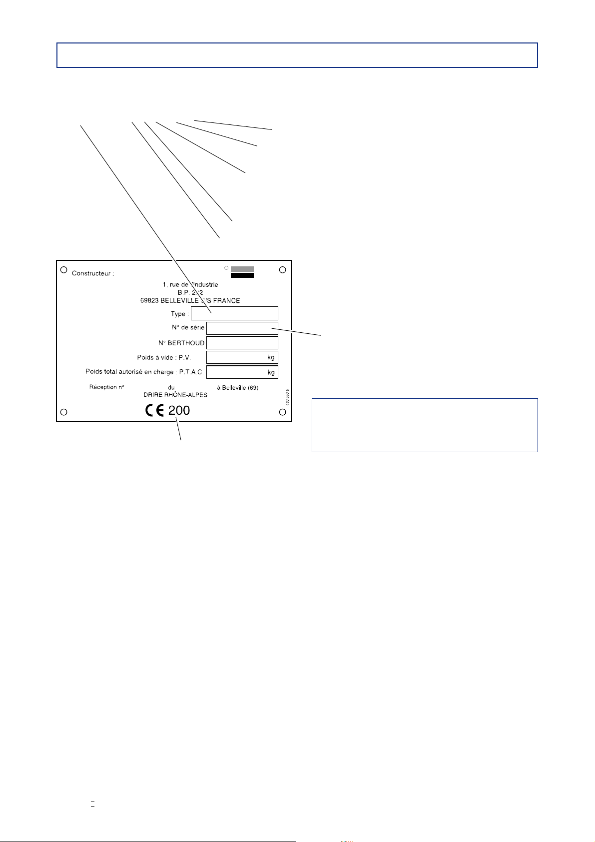
DESCRIPTIVE PLATE
-The location of the descriptive plate on your machine is indicated on the pages 12 and 13.
-The box "Type" is made up of letters and figures.
-Example : BOX E 18 AX 24 24 = 24 metres boom
(28, 30, 32, 36, 38, 40 or 42 metres)
AX = AXIALE boom
EK = EKTAR boom
18 = Tank capacity 1800 litres
25 = Tank capacity 2500 litres
30 = Tank capacity 3000 litres
40 = Tank capacity 4000 litres
E= D.P.Tronic. regulation.
BOX = BOXER device.
The box N°Berthoud is made up of 7 figures.
Example : 100 1179 = order number.
Year and month of manufacture
For the "Poids à vide" (unladen weight) and
"P.T.A.C."
(gross weight)
:
refer to the manufacturer’s plate
located on the front left-hand side of the chassis.
10
82.475 / Boxer II
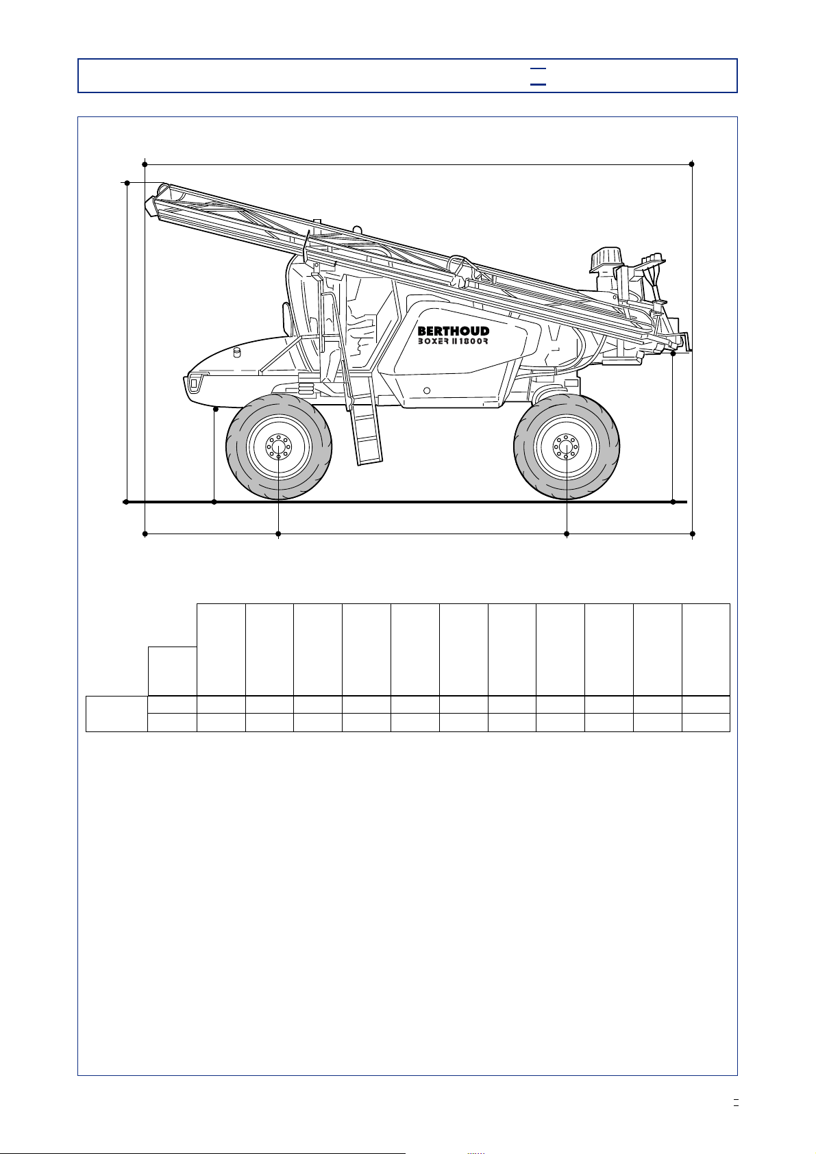
DIMENSIONS (in mm) - BOXER II 1800 R
A - A1
FGH
B
D - D1 - D2
E
Note: Height values are given for original installation of the following tire sizes: 270/95 R 32
Boom
width
A
Total
length
A1
Length
of
boom
arms
B
Total
height
C
Overall
width
DD1
Max.
work
height
under the
nozzle
D2
Min.
work
height
under the
nozzle
E
Ground
clearance
FG
Wheel
base
24 m
28 m
AXIALE
BOXER II
1800 R
7,050 1,100
1,100
5,895
7,020 3,720 2,840
2,840 1,580 2,260 640 1,530 3,600
3,600 1,920

11
82.475 / Boxer II
DIMENSIONS (in mm) - BOXER II 2500 / 3000 / 4000 R
A
2,080 DF
B
J
Boom
width
(in m)
A
Total
length
(1)
B
Max. height
(overall inc.
flashing light
or arm)
(2)
C
Overall
width
(3)
J
Ground
clearance
(4)
D
Wheel
base
F
Swing
clearance
(1)
24
28
30
24
28
30
32
33
24
28
30
32
AXIALE
EKTAR
BOXER II
2500 R
BOXER II
3000 R
BOXER II
4000 R
30
32
36
38
40
42
8,410 to 8,480
8,090 to 8,160
8,190 to 8,260
8,410 to 8,480
8,090 to 8,160
8,190 to 8,260
8,190 to 8,260
8,540 to 8,610
9,000
1,200 to 1,400
1,200 to 1,400
1,200 to 1,400
1,200 to 1,400
1,200 to 1,400
1,200 to 1,400
1,200 to 1,400
1,200 to 1,400
1,340
3,970
3,970
4,100
3,970
3,970
4,100
4,100
4,100
4,200
2,640
2,640
2,860
2,640
2,640
2,860
2,860
2,860
2,720
3,800
3,800
3,800
3,800
3,800
3,800
3,800
3,800
4,315
2,530 to 2,600
2,210 to 2,280
2,310 to 2,380
2,530 to 2,600
2,210 to 2,280
2,310 to 2,380
2,310 to 2,380
2,660 to 2,730
2,590
H - I
Track
1,800 to 3,000
1,800 to 3,000
1,800 to 3,000
1,800 to 3,000
1,800 to 3,000
1,800 to 3,000
1,800 to 3,000
1,800 to 3,000
(1)Variations due to the height where the boom is immobilised in transport and geometry position.
(2)Heightindicated fortheroadclearance1200 and wheels 270/95R48,mayvarywith other road clearances
and other tyres. (Value with flashing light located at the highest point for the AX 24 and AX 28).
(3)Width given from the dimension at the level of the booms and their support. This width may thus be
increased, with the increase in the track and tyre width, to reach a maximum of 3,000 (max. track).
(4)Road clearance corresponding to 270/95 R 48 tyres (may vary with other tyres).
12
82.475 / Boxer II
BERTHOUD
R
agricole
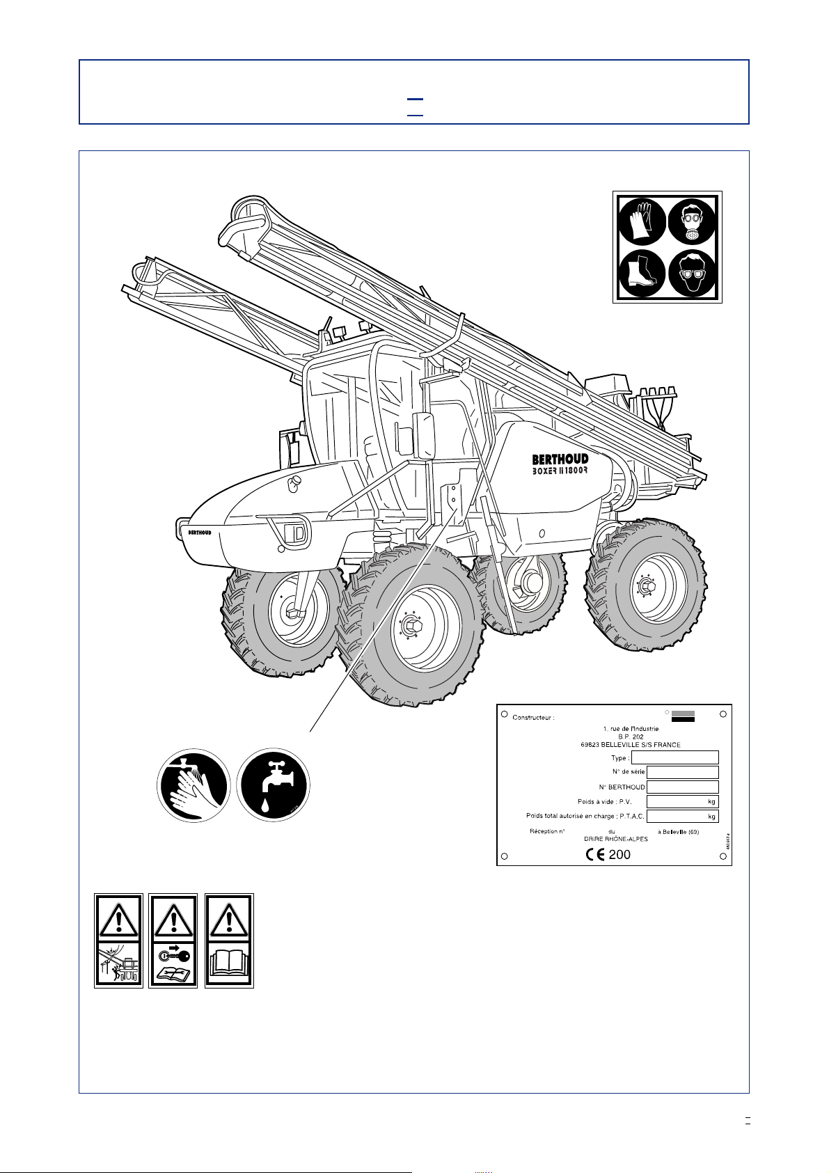
POSITION OFTHE SAFETY STICKERS
- BOXER II 1800 R -
In the cab
417.586
418.630
On the hopper
417.465 417.576
417.572
417.575
On the handwash tank
It is very important to keep the safety stickers in location and in good
condition as they draw your attention to possible dangers and refer to
the operator's manual.
Check their location on the sprayer and see their signification on the
manual No. 82.471 (Safety, checks, maintenance of the Sprayers).
On the boom's fixed frame,
left-hand side
13
82.475 / Boxer II
BERTHOUD
Ragricole
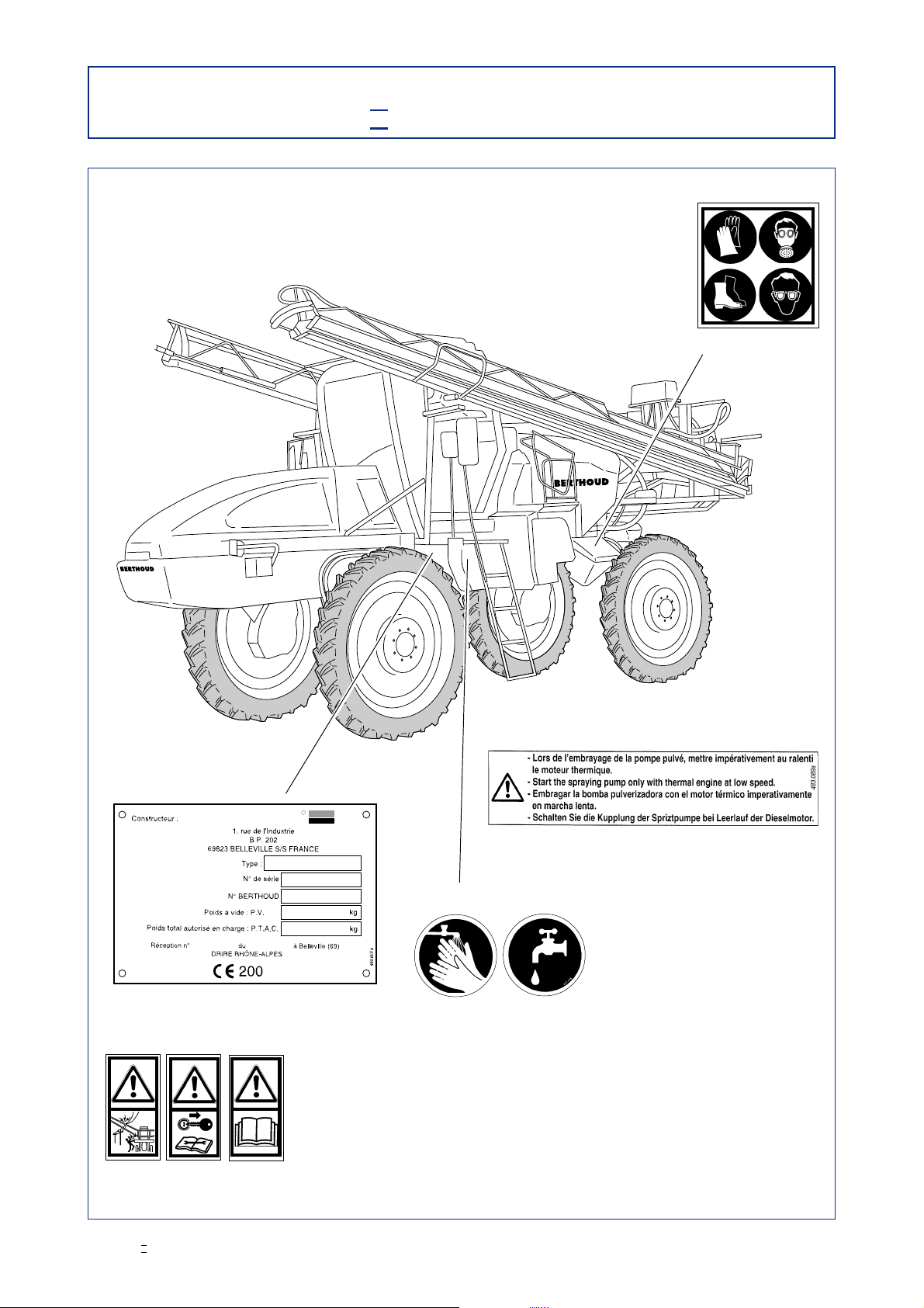
POSITION OFTHE SAFETY STICKERS
- BOXER II 2500 / 3000 / 4000 R -
418.630
On the hopper
417.465 417.576
On the handwash tank
In the cab
417.586 417.572
417.575
It is very important to keep the safety stickers in location and in good
condition as they draw your attention to possible dangers and refer to
the operator's manual.
Check their location on the sprayer and see their signification on the
manual No. 82.471 (Safety, checks, maintenance of the Sprayers).

14
82.475 / Boxer II

15
82.475 / Boxer II
STARTING-UP
THE
SPRAYER
Checking self-propelled advance speed.
Checking self-propelled wheel circumference.
Checking flow rate/hectare.
See manual No. 82.471 "Safety, Checks, Maintenance of the Sprayers".

16
82.475 / Boxer II
RINSING EQUIPMENT BEFORE FIRST USE
Before using your sprayer for the first time with phytosanitary product (weedkillers,
insecticide or other product), rinse the machine completely.
-Remove the nozzles if they are fitted.
-Undo the end plugs on the pipes.
-Fill 1/5th of the volume of the tank with water.
-Spray (Refer to the pump OPERATION section).
-Remove and clean the filters.
-Fit the nozzles.
-Any foreign particles which may be in the hydraulic circuit will thus be eliminated and there will be no risk of
them blocking the holes in the nozzles.

17
82.475 / Boxer II
CHOICE OF NOZZLES
AND
TABLES OF FLOW RATES
See manual No. 82.467
"NOZAL nozzles"
D.P.TRONIC REGULATION
See manual No. 82.465 "D.P.Tronic regulation"

18
82.475 / Boxer II
PRESENTATION OFTHE D.P.TRONIC CONTROL BOX
NOTE
-Fuse: The control box (2) is protected by 3 fuses: diam. 5 x 20 mm:
- 5 Amps for the D.P.TRONIC electronic board (3),
- 10 Amps for the boom control board (4),
- 10 Amps for the boom spraying sections board (5).
I0
Display
Electronic regulation
switches
(see manual No. 82.465)
Control box power
switch
Manual spraying
regulator valve
switch control
7
1
Control switches for boom
(see manuals:
No. 82.438 AXIALE boom
No. 82.461 EKTAR boom)
Plugs
2
4
3
5
6
Manual/automatic mode switch
for regulator valve
Spraying control switches
(see pages 34 to 39)

19
82.475 / Boxer II
MAIN SPRAYER FUNCTIONS
WITH
THE CENTRIFUGAL PUMP
All the valve operations must be done with the engine stopped.
Power up the control box.
When engaging the spray pump,
the internal combustion engine must be at idle.

20
82.475 / Boxer II
TRANSFERRING 9
-To transfer the liquid contained into the tank to another one, proceed as follows:
-To transfer the liquid contained into the tank to another one, proceed as follows (2).
-Turn all the valve handles to position
9
.
-Trip the switch which enables the spraying pump to be engaged.
-Engine speed should kept high enough to permit the filling operation (approximately 2,500 rpm).
FILLING 1
-Close the drain orifice using the valve (1) located under the equipment, in the sump (figure 24, page 43).
-Fill the centrifugal pump priming tank with water.To do this, draw the hexagon socket head screw (1) located
on the upper part of the pump body (figure 1).
-Filling without incorporation hopper using:
- Connect the filling pipe (T1) on the quick-fitting union (3).
- Turn all the valve handles to position
1
.
- Put the pipe (T1) into the liquid to be suck.
- Trip the switch which enables the spraying pump to be engaged.
- Engine speed should kept high enough to permit the filling operation (approximately 2,500 rpm).
When the filling operation is finished, turn valve handle (3) to horizontal position, disconnect the filling
pipe (T1), replace the plug on the quick-fitting union.
-Filling with incorporation hopper using: (see page 28).
RINSINGTHE MAINTANK WITH MAINS WATER 5
-Pump stopped:
-Connect the mains water hose (T3) to the quick connector (2).
-Turn all the valve handles to position
5
.
-Open the water supply.
-Drain the tank via valve (1) (figure 24, page 43).
RINSINGTHE MAINTANK WITHTHE RINSETANK 6
-Pump stopped:
-Turn all the valve handles to position
6
. NOTE: For valve No. (1) place the handle in the position
6
(b)
during 2 minutes, then turn the handle to the normal position
6
(a).
-Power up the control box, (reference 1, figure 17 - page 35).
-Stop spraying: switches (2) placed to the left of the control box (5) and press push-button (4) (figure 17 -
page 35).
-Trip the switch which enables the spraying pump to be engaged.
-Engine speed should be held at 1,400 rpm for proper rinsing.
-Drain the tank via valve (1) (figure 24, page 43).
RINSINGTHE SPRAYING CIRCUIT WITHTHE RINSETANK 7
-Pump stopped:
-Turn all the valve handles to position
7
.
-Power up the control box, (reference 1, figure 17 - page 35).
-Open spraying: switches (2) placed to the right of the control box (5) and press push-button (3) (figure 17 -
page 35).
-Trip the switch which enables the spraying pump to be engaged.
-Engine speed should be held at 1,400 rpm to obtain proper rinsing pressure.
This operation is not enough when changing chemical products.
CENTRIFUGAL PUMP FUNCTIONS (figure 2)
- BOXER II 1800 R -
This manual suits for next models
3
Table of contents
Other Berthoud Farm Equipment manuals


