Berthoud AXIALE II SEH Series User manual
1
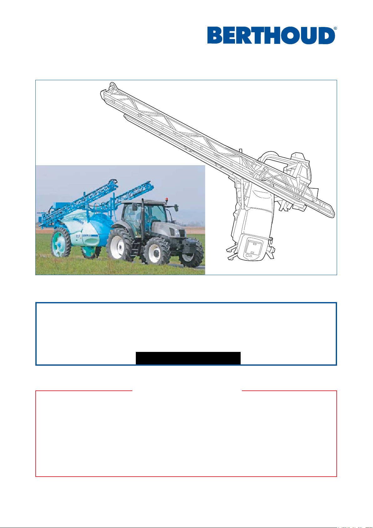
82.486 "AXIALE II" Booms
IMPORTANT ADVICES
- InorderthattheAXIALEIIsuspensionprovidesyouwithcompletesatisfaction:
- running in is needed, and this takes place in the first few hours of operation,
- it is highly recommended that you grease moving and frictional parts before each use.
- Choose correct advance speed for your field, and do not make rapid or ill-considered changes of direction:
thisprolongsservicelife.
- Regularly check nozzles and lines because these can become blocked or worn; check flow rate.
- Toensurecorrectattachmentandoperationofsprayboom,followallthefittingandoperationadviceinthis
manual.
"AXIALE II" BOOMS
SEH - ED 24/27/28/30/32/33 metres
82.486-A ENGLISH © BERTHOUDAgricole02/2008
Wiring diagrams: see Agent manuals

282.486 "AXIALE II" Booms
See pages
- Technicalspecifications.................................................................... 3
- "AXIALE"suspension........................................................................ 3
- Boom arm section dimensions ......................................................... 4
- Layout of spraying sections.............................................................. 5
- Adjustment of the arms..................................................................... 6
- Locking of a boom with an hydraulic lock ......................................... 10
- Locking of a boom with a mechanical lock ....................................... 10
- Flowlimitersonintermediate arm ..................................................... 10
- Adjustmentoflowering andsuspensionoftheboom ........................ 12
- Armsupport adjustments.................................................................. 12
- Adjustment of the arm stops............................................................. 12
- Boom heightintransportposition ..................................................... 12
- Slopecorrection cylinderspeedadjustment ..................................... 14
- Adjustment ofthe angle correctorreset option ................................. 14
- Centralpartadjustment..................................................................... 14
- Adviceonboommaintenance ........................................................... 16
- Usersafety ....................................................................................... 16
- Electrical control box of the "AXIALE II" ED boom
with hydraulic lock ............................................................................ 17
- Electrical control box of the "AXIALE II" ED boom
with mechanical lock ........................................................................ 18
- "AXIALEII"ED boomoptions ........................................................... 19
- Electrical control box of the "AXIALE II" SEH boom
with mechanical lock ........................................................................ 20
summary
Presentation and operation of the electrical control box:
refer to the technical manual of your device.
3
82.486 "AXIALE II" Booms
- Suspension"autostable pendular" type.
- Boomframe mounted onparallelogram.
- Anti-whip structure based on trianguled concept.
- Steel structure protected by surface treatment, and polyester paint heat treated in furnace.
- Indicatorsfor height, angle correction and geometry.
- Allhydraulicfunctions controlled by electro-hydraulic spool valves or electro-hydraulic selector.
- Boom ends with break-back protection in 3 dimensions.
- Nozzle-holder piping made of Ø 25 x 23 polypro or stainless steel.
- Spacingbetween nozzle-holders: 0.50 m.
- Quadrixnozzle-holders with diaphragm anti-dripdevice.
- NOZALnozzle-nut mounted 1/8 turn.
TECHNICAL SPECIFICATIONS
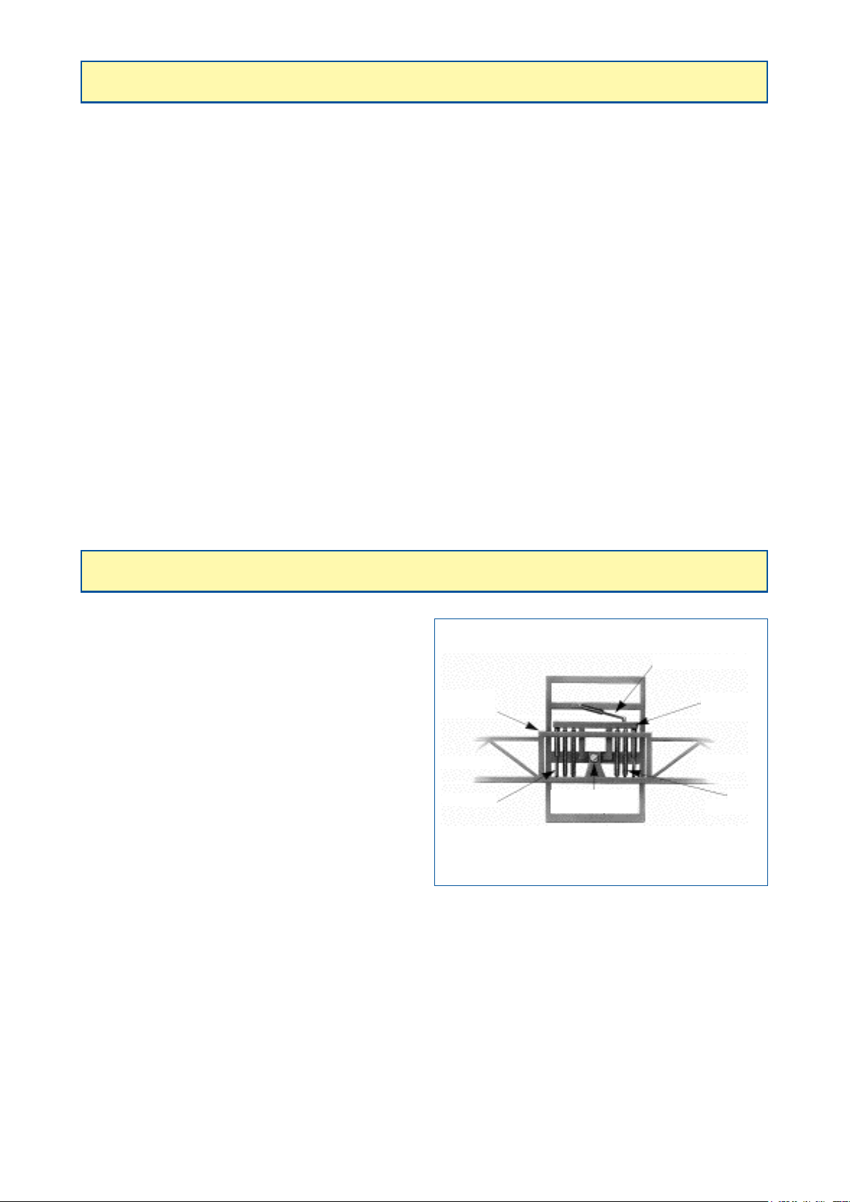
"AXIALE" SUSPENSION
Boom arm Boom arm
Mobile frame of
the boom
Level correcting ram
Shock absorbers
Floating or
stabilizing
bar
Balance
spring
Boom central
balance point
- TheAXIALE suspension "autostablependular" type,
isbased ontheprinciple ofabalance positioned near
thegravity center of the boom.
- Balanceis maintained, and, consequently,the boom
remains parallel to the axle, as a result of the action
of 4 springs (20/21/24/27/28 m) or for 6 springs
(30/32/33m).
- These springs continuously correct position of the
boom.
- Two shock absorbers provide a final filter against
shocks.
- Angle correction, is provided by a ram acting on the
floating and stabilizing bar to which the springs are
attached.
482.486 "AXIALE II" Booms
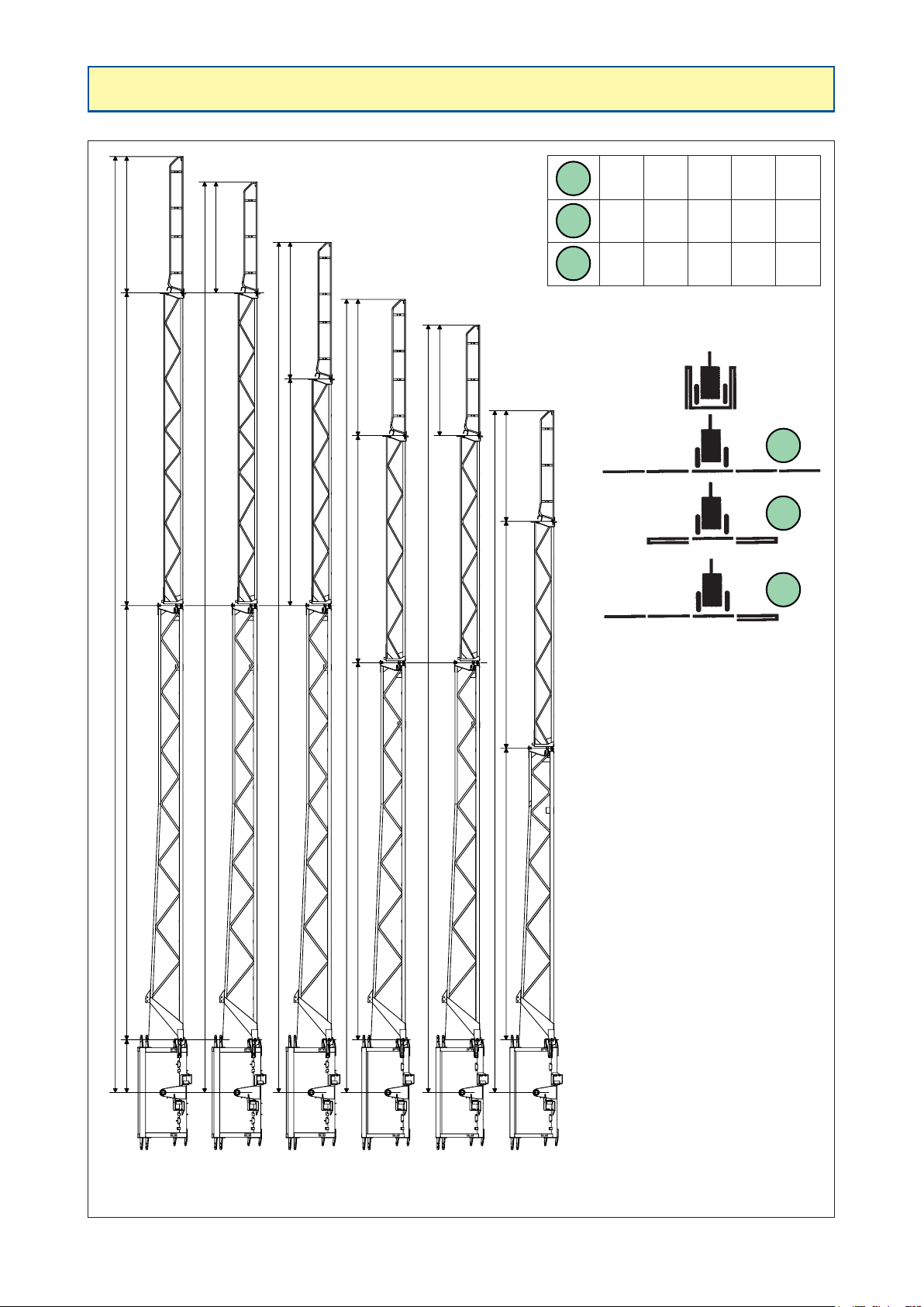
BOOM ARM SECTION DIMENSIONS (frame)
16403
7606
926 2389
1939
2389
2389
1939
19393977
11948
5106
6606
13448
15953
14898
13898
3977
3977
24 m
27 m
28 m
30 m
32 m
33 m
5482
A
C
B
24m
12m
18m
A
B
C
28m
14m
21m
30m
17m
23.5m
32m
17m
24.5m
33m
17m
25m

5
82.486 "AXIALE II" Booms
LAYOUT OF SPRAYING SECTIONS
Boom
width Number of
sections Number of nozzles per section
20 m 4 10 - 10 - 10 - 10
20 m 5 8 - 10 - 4 - 10 - 8
21 m 4 11 - 10 - 10 - 11
21 m 5 9 - 8 - 8 - 8 - 9
24 m 4 12 - 12 - 12 - 12
24 m 6 8 - 8 - 8 - 8 - 8 - 8
24 m 7 6 - 6 - 8 - 8 - 8 - 6 - 6
27 m 4 13 - 14 - 14 - 13
27 m 7 7 - 8 - 8 - 8 - 8 - 8 - 7
28 m 4 14 - 14 - 14 - 14
28 m 7 8 - 8 - 8 - 8 - 8 - 8 - 8
30 m 5 12 - 12 - 12 - 12 - 12
30 m 6 10 - 10 - 10 - 10 - 10 - 10
30 m 7 9 - 9 - 9 - 6 - 9 - 9 - 9
30 m 7 6 - 7 - 12 - 10 - 12 - 7 - 6
32 m 5 13 - 13 - 12 - 13 - 13
32 m 6 12 - 10 - 10 - 10 - 10 - 12
32 m 7 9 - 9 - 9 - 10 - 9 - 9 - 9
32 m 8 8 - 8 - 8 - 8 - 8 - 8 - 8 - 8
33 m 6 11 - 11 - 11 - 11 - 11 - 11
Breakdown of the 32 m frame (in terms of nozzles ½ m) = 4 - 11 - 15 - 4 - 15 - 11 - 4
Breakdown of the 33 m frame (in terms of nozzles ½ m) = 5 - 11 - 15 - 4 - 15 - 11 - 5
Breakdown of the 20 m frame (in terms of nozzles ½ m) = 4 - 4 - 10 - 4 - 10 - 4 - 4
Breakdown of the 21 m frame (in terms of nozzles ½ m) = 5 - 4 - 10 - 4 - 10 - 4 - 5
Breakdown of the 24 m frame (in terms of nozzles ½ m) = 4 - 8 - 10 - 4 - 10 - 8 - 4
Breakdown of the 27 m frame (in terms of nozzles ½ m) = 4 - 8 - 13 - 4 - 13 - 8 - 4
Breakdown of the 28 m frame (in terms of nozzles ½ m) = 5 - 8 - 13 - 4 - 13 - 8 - 5
Breakdown of the 30 m frame (in terms of nozzles ½ m) = 5 - 8 - 15 - 4 - 15 - 8 - 5

682.486 "AXIALE II" Booms
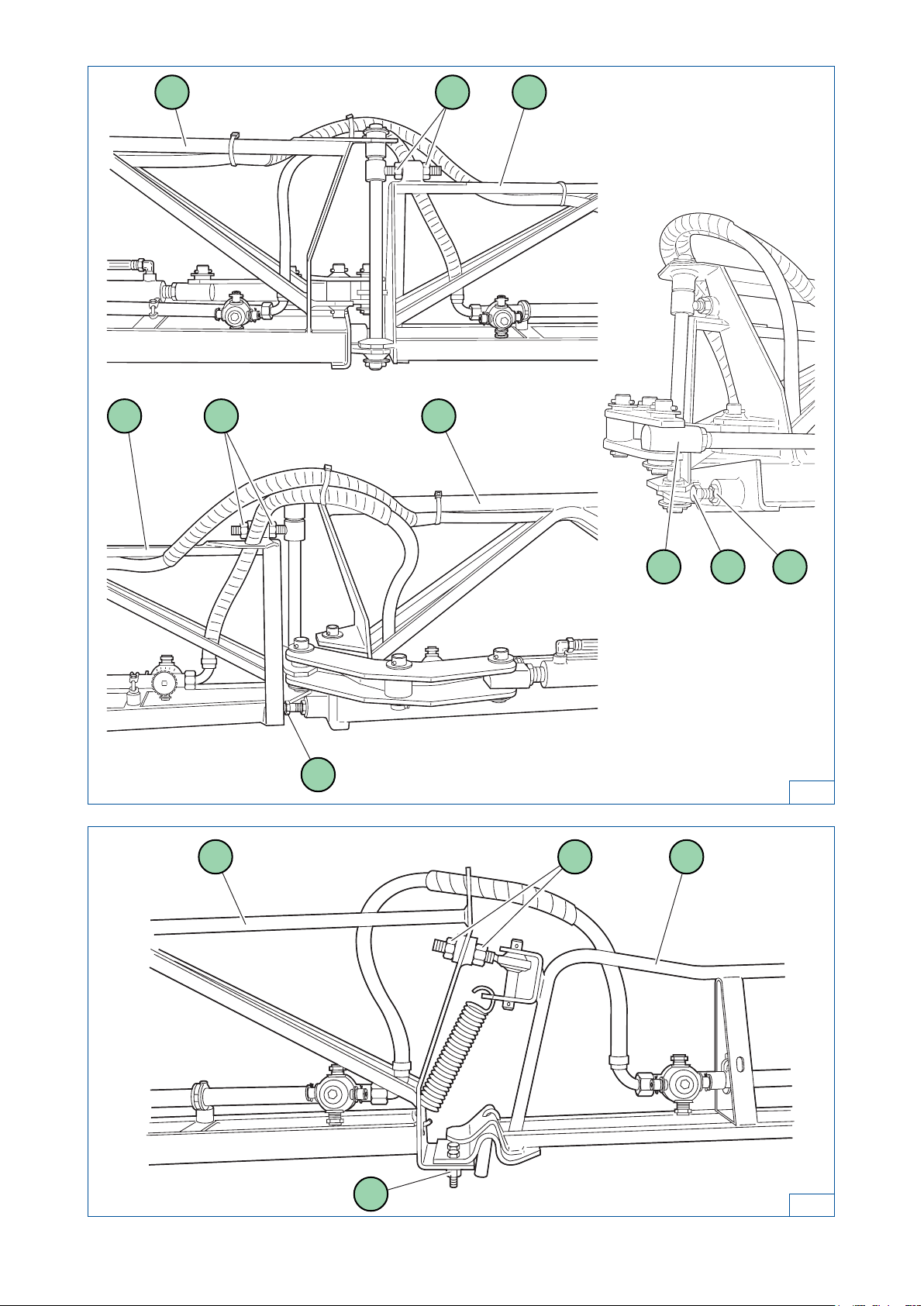
ADJUSTMENT OF THE ARMS
ADJUSTMENT OF THE BOOM
- Your boom is equipped with a device which adjustsarm alignment in working position and adjustment for
thetransportposition.
ADJUSTMENT OF THE MAIN ARMS
IN TRANSPORT POSITION (figure 1):
Arms closed in transport position (they must be fully against the arm supports).
- Removethepin (5) (figure 1) then actuate the unfolding actuators (1) in open position (end of travel).
- Adjustment of the ball joint (4):
- unscrew the set screw (2),
- unscrew the socket (3) to gain access to the set screw (6),
- adjust the ball joint (4) so that the pin (5) can be replaced easily,
- tighten the set screw (6) and adjust the socket (3) for working position.
IN WORK POSITION (IN THE HORIZONTAL PLANE):
Open the arms fully.
- Check the alignment in the horizontal plane.
- If not horizontal, decompress the actuators, then loosen the set screw (2) so that you can tighten or
loosen the socket (3) (figure 1).
- Open the arm again to check the alignment.
- Repeat the operation until the desired setting is obtained.
- Tighten the set screw (2).
IN WORK POSITION (IN THE VERTICAL PLANE):
Open the arms fully.
• Case of booms without GV (variable geometry) (figure 2):
- Adjust the main arms (2) by turning the coupler (1) positioned on the upper part of the arm.
• Case of booms with GV (variable geometry) (figure 4):
- Thesebooms areequipped with aposition indicator(2)and anoptional automatic reset(2 positionsensors
(1) (figure 3)). The actuator (1) (figure 4) is used to incline the arm.
• Adjustment of reset sensors (figure3):
- If your reset is not correct adjusted:
- open the arms in work position (see electrical control box, pages 17, 18 and 20),
- loosen the nuts (2),
- slide the sensors (1) into the opening up to the limit of illumination of the LED located on top of the
sensor; when the LED goes out, retighten the nuts of the sensor.
WARNING:
The sensors (1) (figure 3) must have a clearance (a) between 2 and 4 mm.
WARNING:
- Spray equipped with GV (variable geometry):
The GV must be positioned on 0 before folding the boom.

7
82.486 "AXIALE II" Booms
2
1 2
3
2
1
a
4
1
2
1
5
3
2
1 4
62
Detail of the ball joint

882.486 "AXIALE II" Booms
ADJUSTMENT OF THE ARMS (continuation)
ADJUSTMENT OF THE INTERMEDIATE ARMS (figure 5)
- Adjustment of the intermediate arm (2) in relation to the main arm (1).
- Place the arms in open position.
IN THE VERTICAL PLANE:
- Turnnuts (3) for vertical adjustment.
IN THE HORIZONTAL PLANE:
- Turnnut(4)and bolt (5) for horizontal adjustment.
- Note : When changing the folding cylinder of the intermediate arm (2), the adjustment of the yoke (C) must be
carried out with the boom closed and the cylinder shaft extended.
ADJUSTMENT OF THE END ARMS (figure 6)
IN THE VERTICAL PLANE:
- Turn nuts (6) for vertical adjustment of the end arms (7) in relation to the intermediate arms (2).
IN THE HORIZONTAL PLANE:
- Loosen bolts (8), and place the end arm (7) in the proper plane. Once adjusted, tighten the bolts.
9
82.486 "AXIALE II" Booms
6
2 6 7
8
5
1 3 2
C 5 4
2 3 1
5

10 82.486 "AXIALE II" Booms
LOCKING OF A BOOM WITH AN
HYDRAULIC LOCK (figure 7)
- Before making any adjustments, make sure that the central part is in horizontal position.
To adjust the lock, extend the actuator rods (1), loosen the locknuts(2), end tips(3) fully against the oscillating
framethen retighten the locknuts (2).
LOCKING OF A BOOM WITH A
MECHANICAL LOCK (figure 9)
- The adjustment of a boom with mechanical lock is done with the boom open in raised, horizontal position.
- The cable (3) must be tightened by screw/nuts (4), without hindrance.
- Ifthe cable is not taut,loosen the eyebolts/nuts (4)completely, tighten the cable using the twocable clamps(5)
only, they retighten it using the eyebolts/nuts (4).
-Note : To use the boom in HIGH POSITION, on each side, you must withdraw the joining shackle (6) from the
oscillating frame (7), and hook the joining shackle (6) on the ring (2) of the lock (1).
FLOW LIMITERS ON INTERMEDIATE ARM (figure 8)
- The flow limiters (1) fitted on the boom's rams are used to adapt the speed of the boom's lifting and folding
movementsto suit the fluidity of the oil and the flow rate of the tractor within the limits of good agricultural use.
- Procedure:
- Unscrew the hex-socket cap screw (2) situated in the flow limiter's adjusting wheel (3).
- Adapt the flow limiter's setting.
- Make sure that the adjustment is correct (speed of movement not too fast).
- Tighten the hex-socket cap screw (2).
IMPORTANT:
- The adjustment must be carried out without anyone in the boom's working radius
and without risk of untimely movement of the boom.
WARNING:
- Before folding the boom, replace the cables (3) correctly on the oscillating frame (7).
IMPORTANT :
- Before each treatment and after unfolding arms, the boom must be unlocked.
- Before folding arms and during transport operation, lock the boom to the oscillating
frame (refer to the technical manual of your device).

11
82.486 "AXIALE II" Booms
1
3 2
87
2
3
1
9
4 5
3
1 2
6 7

12 82.486 "AXIALE II" Booms
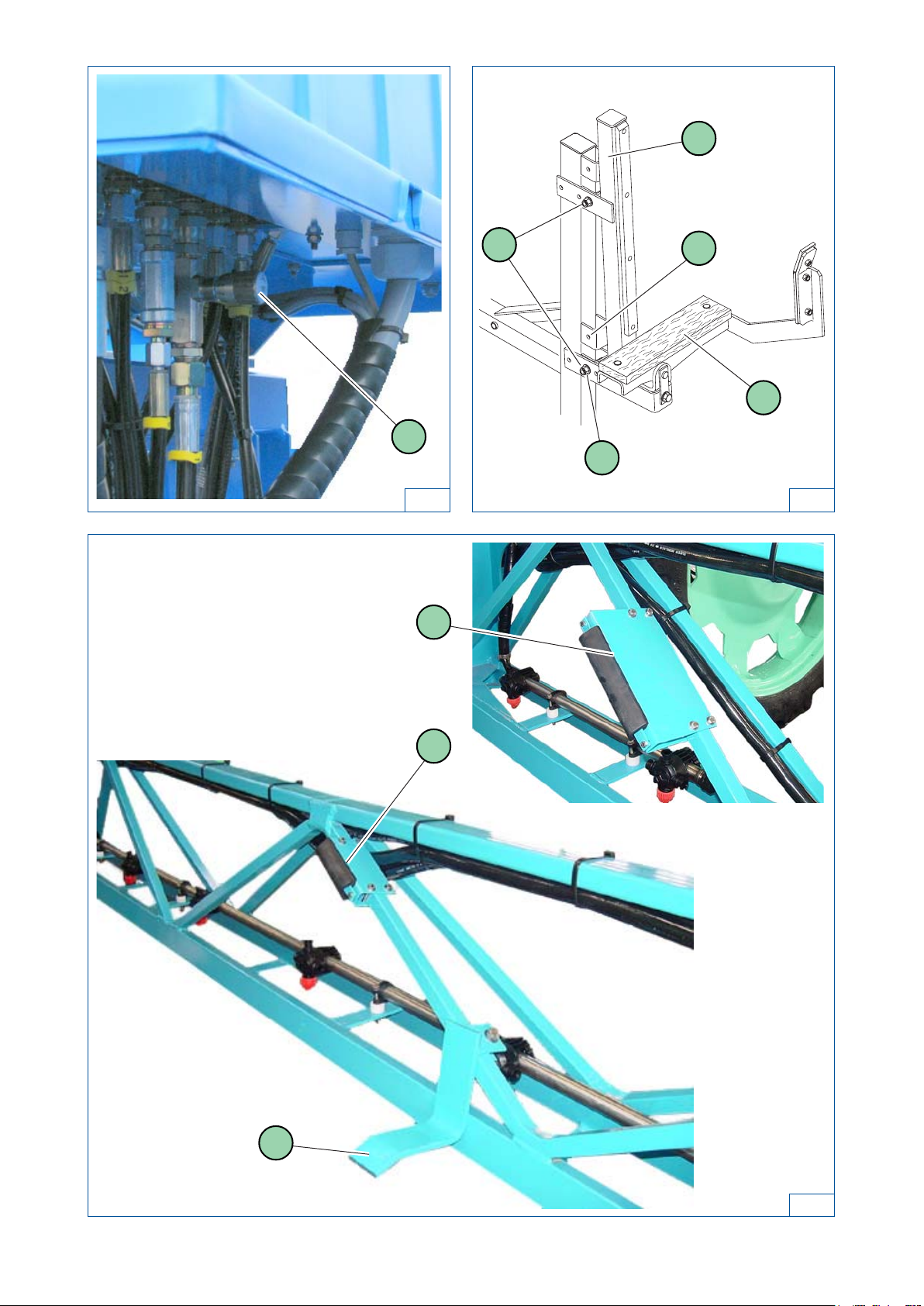
ADJUSTMENT OF LOWERING AND SUSPENSION
OF THE BOOM (figure 10)
- The limiter (1), located below the hydraulic units, is used to set the boom's lowering speed.
- Nitrogencylinders mounted on the raising cylinders are used for vertical damping of the boom.
(The more open the limiter, the more brutal the shocks. Do not close the limiter completely).
ADJUSTMENT OF ARM SUPPORTS (figure 11)
- The boom is mounded on the sprayer in low position.
- It can be raised using the arm supports (2).
- With the boom in closed position, adjust the arm supports 10 cm above the wood plate (3).
- Removethe bolts (1), respecttheholes used to ensureproperinclination of the supportandplace the supports
(2) in position (A) or (B).
- Replace the bolts.
- Note: When at rest or during road transport, lower the boom so that it touches the arm support wood plates
(3)alongtheir entire length.
Do not attempt to lower the boom beyond this point as damage may be result.
WARNING:
- Sprayer with axle suspension:
When folding the boom arms, leave at least 150 mm between the top of the tank and
the main arm (make modifications with arm geometry).
WARNING:
- Spray equipped with GV (variable geometry):
The GV must be positioned on 0 before folding the boom.
ADJUSTMENT OF THE ARM STOPS (figure 12)
INTERMEDIATE AND END ARM'S STOP
- Makesure that stops (1), (2) and (3) correctly touch the intermediate andendarmswhen the boom is in folded
position.
- To do this, loosen the nuts, move the stops and tighten the nuts.
BOOM HEIGHT IN TRANSPORT POSITION
- Whenlowering the boom onto itssupports, always ensure that thereisat least 100 mm betweentheboom arm
and the tank.
13
82.486 "AXIALE II" Booms
11
1
10
12
1
2
3
A
1B
2
3

14 82.486 "AXIALE II" Booms
SLOPECORRECTIONCYLINDERSPEEDADJUSTMENT
(figure13)
- The limiter (1), located on the slope correction cylinder is used to adjust its speed.
- Procedure:
- Unscrew the hex-socket cap screw (2) situated in the flow limiter's adjusting wheel (3).
- Adapt the flow limiter's setting.
- Make sure that the adjustment is correct (speed of movement not too fast).
- Tighten the hex-socket cap screw (2).
ADJUSTMENT OF THE ANGLE CORRECTOR
RESET OPTION (figure 14)
- Adjustment of reset sensors:
- If your reset is not correct adjusted:
- check that the mobile frame (3) is level (arms open),
- loosen the nuts (2),
- slide the sensors (1) into the opening up to the limit of illumination of the LED located on top of the
sensor; when the LED goes out, retighten the nuts of the sensor.
CENTRAL PART ADJUSTMENT (figure 15)
INSPECTION OF THE CENTRAL PART:
- Your boom is equipped with an anti-whipping device to ensure the best possible boom behaviour; regularly
check that the 2 bolts (3) are tightened.
SYNCHRONISATION OF THE MAIN ARMS:
- Thisdevice consists of a flow divider (1) and two flow limiters (2) with a built-in control valve. No adjustment is
necessary for the opening and closing speed of the main arms.
WARNING:
- The sensors (1) must have a clearance (a) between 2 and 4 mm.

15
82.486 "AXIALE II" Booms
14
12
13
31 2
3
15
22 3
1
a

16 82.486 "AXIALE II" Booms
- After each use, rinse pipework by operating equipment with clean water for a few minutes.
- Drain pipes, especially if there is risk of frost.
- Keep arm joints, articulation cam faces, ball joints, fixed frame uprights and the central boom pin greased
(greasenipple).
- After cleaning the unit with a high-pressure sprayer, grease or oil cylinder shafts.
- Keeppaintworkin good condition, repainting chipped areas.
(Paint used: BERTHOUD 769.077 blue aerosol).
- Recommendations for lubrification: TOTAL FINA ELF : LICAL EP 2
Lubrication of the central axis: KLUBER 46 MR 401 grease, BERTHOUD reference 786.703
ADVICE ON BOOM MAINTENANCE
- Whenhandlingcroptreatmentproducts use appropriate safety clothing.
- When adjusting spray boom the equipment must be fixed in rest position.
- Duringopening and closing of arms all personnel must be outside the area of movement.
- When towing at night, the equipment must be not obscure tractor lighting and direction
indicator or lamps; if needed, fit supplementary lamps.
USER SAFETY

17
82.486 "AXIALE II" Booms
WHEN WORKING
- To modify the boom height, use switch (3):
- raise it to lift the boom,
- push it down to lower the boom.
- If you want to fold an arm on the right or left, you must do the following:
- lock the boom by raising switch (2) and hold it,
- lift the boom, using switch (3),
- lower switch (9) or (10) and hold it until the right or left arm is completely closed.
- To modify the angle corrector, push switch (4):
- totheright for right-hand angle,
- totheleftforleft-hand angle.
- Tomodifythe variablegeometry,push switch(11)for right-handgeometry,or switch(12)forleft-handgeometry:
- switches (11) and (12) raised, the arms raise,
- switches(11)and (12) lowered, the arms lower.
UNFOLDING ARMS
1 - POWERUP THECONTROL BOX
Raise switch (1), the red lamp (a) lights.
2 - LOCKINGTHE BOOM(before anyother operation)
Raiseswitch (2) andholdit, locking occursas soon
as the red lamp (b) lights.
3 - CLEARANCE OF THE BOOM FROM ITS
SUPPORTS
Raise switch (3) and hold it until the boom is
completely clear of its supports.
4 - UNFOLDINGTHEMAINARMS
Raiseswitch(8) and hold it until the main arms are
completelyopened.
5 - UNFOLDINGTHEEND RIGHTARM
Raise switch (9) and hold it until the end right arm
iscompletely opened.
6 - UNFOLDINGTHEEND LEFTARM
Raise switch (10) and hold it until the end left arm
iscompletely opened.
7 - ADJUSTMENTOF BOOMHEIGHT
Raise switch (3) and hold it to lift the boom.
Lower switch (3) and hold it to lower the boom.
8 - UNLOCKINGTHE BOOM
Lowerswitch(2) andhold itduring severalseconds,
lamp(b) extinguished.
FOLDINGARMS
1 - LOCKINGTHE BOOM(before anyother operation)
Raiseswitch (2) andholdit, locking occursas soon
as the red lamp (b) lights.
2 - ADJUSTMENTOF BOOMHEIGHT
Raise switch (3) and hold it until the boom its at is
maximumheight.
3 - FOLDINGTHEEND RIGHTARM
Lower switch (9) and hold it until the end right arm
is completely closed.
4 - FOLDINGTHEEND LEFTARM
Lower switch (10) and hold it until the end left arm
is completely closed.
5 - FOLDINGTHEMAINARMS
Lowerswitch (8) and hold ituntilthe main arms are
completely closed.
6 - LOWERTHE BOOM ONTO THESUPPORTS
Lower switch (3) and hold it until the boom rest
completely on the right and left supports.
ELECTRICALCONTROLBOX ofthe"AXIALEII"EDBOOM
withHYDRAULICLOCK
(figure16)
Sprayer empty without hydraulic unit:
Disengagethetractor’spowertake-offtonot
turn the Delta pump empty.
Sprayer empty with hydraulic unit:
Engage the tractor’s power take-off the
minimumamount of time necessary to fold/
unfold the arms so as not to turn the Delta
pump empty for a long time.

18 82.486 "AXIALE II" Booms
UNFOLDING ARMS
1 - POWERUP THECONTROL BOX
Raise switch (1), the lamp (a) lights.
2 - RAISINGTHE BOOM (before anyother operation)
Raiseandholdswitch(3)untilthemaximumposition
is reached. (Locking the boom).
3 - UNFOLDINGTHEMAINARMS
Raiseswitch(8) and hold it until the main arms are
completelyopened.
4 - UNFOLDINGTHERIGHTOR LEFTENDARMS
Raiseand hold switch (9)or(10) until the endarms
arecompletely opened.
5 - ADJUSTMENTOF BOOMHEIGHT
Raise switch (3) and hold it to lift the boom.
Lower switch (3) and hold it to lower the boom.
FOLDINGARMS
1 - RAISING THEBOOM (before anyotheroperation)
Raiseandholdswitch(3)untilthemaximumposition
is reached. (Locking the boom).
2 - FOLDINGTHE RIGHTORLEFTENDARMS
Lower switch (9) or (10) and hold it until the end
arms are completely closed.
3 - FOLDINGTHEMAINARMS
Lowerswitch (8) and hold ituntilthe main arms are
completely closed.
4 - LOWER THEBOOM ONTO THE SUPPORTS
Lower switch (3) and hold it until the boom rest
completely on the right and left supports.
ELECTRICALCONTROLBOX ofthe"AXIALEII"ED BOOM
withMECHANICALLOCK
(figure16)
WHEN WORKING
- To modify the boom height, use switch (3):
- raise it to lift the boom,
- push it down to lower the boom.
- If you want to fold the right or left end arms, you must do the following:
- raise the boom to its highest position,
- use switch (3) and hold it to lock the boom,
- lower switch (9) or (10) and hold it until the right or left end arms are completely closed.
- To modify the angle corrector, push switch (4):
- totheright for right-hand angle,
- totheleftforleft-hand angle.
- To modify the variable geometry (in option), push switch (11) for right-hand geometry, or switch (12) for left-
handgeometry:
- switches (11) and (12) raised, the arms raise,
- switches(11)and (12) lowered, the arms lower.

19
82.486 "AXIALE II" Booms
"AXIALE II" ED OPTION
IMPORTANT : For road operation, the angling drawbar or tracker must be blocked (pin G,
figure 17). For field work, remove the pin (G).
ANGLING DRAWBAR OPTION: (1switch)
- Push switch to the right or left to move the drawbar.
ANGLING DRAWBAR OPTION WITH RESET: (1switch + 1 push-button)
- Push switch to the right or left to move the drawbar.
- Press and hold push-button until the red indicator light (c) comes on; the drawbar is aligned.
TRACKER OPTION: (2 switches +1push-button)
- ROADPOSITION:
- Lower switch , the tracker is not in service, the green indicator light (d) goes out.
- Press and hold push-button until the red indicator light (c) comes on: the drawbar is aligned.
- FIELDPOSITION(Tracker):
- Raise switch , the green indicator light (d) comes on; the tracker is ready for field operation.
1716 G
Electrical control box 290 x 271 mm
BERTHOUD
BERTHOUD
PROG
PROG
VALID
VALID
FIN
FIN
C
VOL/ha
VOL/ha
INFO
INFO
PRESS
PRESS
DIST
DIST
SURF
SURF
1
0
0
M
0
1
a
2
b
35
c
6
7
d
8
9
10
11
12
14
4
Electrical control box 406 x 290 mm
BERTHOUD
-
+
I
0
Berjust 2000
insert
info
insert
l / ha
hm/h
hl
ha
m-km
0
M
0
Electrical control box 297 x 214 mm
BERTHOUD
PROGVALID FIN
C
VOL/ha
INFO
PRESS
DIST
SURF
1
0
PROGVALID FIN CLEAR
PRINT
0
M
0

20 82.486 "AXIALE II" Booms
WHEN WORKING
- To modify the angle corrector, set the selector switch (2) in position (D), and actuate the handle of the
tractor'sdoubleeffecthydraulic distributor.
UNFOLDING ARMS
1 - POWERUP THECONTROL BOX
Raise switch (1), the lamp (a) lights.
2 - CLEARANCE OF THE BOOM FROM ITS
SUPPORTS
Without tracking drawbar option:
Actuate the tractor's double effect hydraulic
distributor until the boom is completely off its
supports.
With tracking drawbar option:
Raise switch and hold it until the boom is
completely clear of its supports.
3 - UNFOLDINGTHE MAINARMS(BP)
Set the selector (2) to position (BP) and actuate
the handle of the tractor's double effect hydraulic
distributor until the main arms are completely
unfolded.
4 - UNFOLDINGTHEENDARMS(BE)
Set the selector (2) to position (BE) and actuate
the handle of the tractor's double effect hydraulic
distributor until the end arms are completely
unfolded.
5 - ADJUSTMENTOF BOOMHEIGHT
Without tracking drawbar option:
Actuate the handle of the tractor's double effect
hydraulic distributor to adjust boom height.
With tracking drawbar option:
Raise switch and hold it to lift the boom.
Lower switch and hold it to lower the boom.
FOLDINGARMS
1 - RAISE THEBOOM
Without tracking drawbar option:
Actuate the handle of the tractor's double effect
hydraulic distributor to lift the boom.
With tracking drawbar option:
Raise switch and hold it to lift the boom.
2 - FOLDINGTHE END ARMS (BE)
Set the selector (2) to position (BE) and actuate
the handle of the tractor's double effect hydraulic
distributoruntil theend arms arecompletely folded.
3 - FOLDINGTHE MAINARMS (BP)
Set the selector (2) to position (BP) and actuate
the handle of the tractor's double effect hydraulic
distributoruntilthemain armsarecompletely folded.
4 - LOWER THEBOOM ONTO THE SUPPORTS
Without tracking drawbar option:
Actuate the handle of the tractor's double effect
hydraulic distributor to lower the boom onto the
armsupports.
With tracking drawbar option:
Lowerandholdswitch tolower the boom onto
the arm supports.
In road position,
set the selector switch (2) to 0.
ELECTRICALCONTROLBOXofthe "AXIALEII"SEHBOOM
withMECHANICALLOCK
(figure18)
This manual suits for next models
1
Table of contents
Other Berthoud Farm Equipment manuals


Popular Farm Equipment manuals by other brands

Schaffert
Schaffert Rebounder Mounting instructions

Stocks AG
Stocks AG Fan Jet Pro Plus 65 Original Operating Manual and parts list

Cumberland
Cumberland Integra Feed-Link Installation and operation manual

BROWN
BROWN BDHP-1250 Owner's/operator's manual

Molon
Molon BCS operating instructions

Vaderstad
Vaderstad Rapid Series instructions


