Lipco WP 60 User manual


Instructions
Pathway weeder WP 60/75/90/100/125
2 - 20
120131-05-EN BA WP 60_75_90_100_125 / 29.06.2020
1. Introduction
Dear Customer,
We thank you for having chosen a LIPCO Pathway Weeder WP. We
hope that you will be happy with your choice.
In order that your LIPCO Pathway Weeder WP will serve you well for
many years, we ask you to pay close attention to operating
instructions which you will find in this manual. This will help you to
prevent breakdowns and accidents resulting from non-observance of
the operating instructions, for which our company will not accept
responsibility.
This Instruction and Maintenance Manual is to be considered an
integral part of the machine itself and therefore it must always
accompany the machine when it is sold, even in the event of its sale
to third parties.
If you keep this manual in a safe place and in good condition, you -
and whoever must use the machine - will be able to have a complete
reference on hand at all times.
Note:
The illustrations, descriptions and specifications in this manual are
not binding. LIPCO reserves the right to make modifications without
notice.

Instructions
Pathway weeder WP 60/75/90/100/125
3 - 20
120131-05-EN BA WP 60_75_90_100_125 / 29.06.2020
2. Contents page
1. Introduction..................................................................................2
2. Contents ...................................................................3
3. Designated use............................................................................4
4. Warning signs attached to the machine......................................5
5. Safety regulations........................................................................6
6. Accident prevention.....................................................................7
7. Preparation..................................................................................9
8. Connection to the engine-driven machine.................................10
9. Adjustment of the working depth...............................................11
10. Working with the edge cutter ....................................................11
11. Technical data...........................................................................13
12. Maintenance..............................................................................14
13. Replacement of the tools ..........................................................16
14. After use....................................................................................17
15. Warranty....................................................................................18
16. EC Declaration of Conformity ...................................................19

Instructions
Pathway weeder WP 60/75/90/100/125
4 - 20
120131-05-EN BA WP 60_75_90_100_125 / 29.06.2020
3. Designated use
The LIPCO Pathway Weeder WP, when connected to single axle
tractors / power mowers, is designed for weed removal from water-
logged surfaces.
Any other use for purposes other than those described here is
considered contrary to the designated use. The manufacturer cannot
be held liable for damage resulting from such use; the risk for such
use lies entirely with the user.
Operating the unit within the limits of its designated use also means
following the instructions for operation, transport and maintenance
described by the manufacturer.
Any work, maintenance and repair on the LIPCO Pathway Weeder
WP must be carried out only by persons who are familiar with the
unit and have been informed about possible risks!
The relevant accident prevention regulations as well as the other
generally recognized maintenance, safety, industrial medicine and
road traffic rules and instructions must be observed.
The manufacturer cannot be held liable for damage resulting from
unauthorized modifications of the LIPCO Pathway Weeder WP.

Instructions
Pathway weeder WP 60/75/90/100/125
5 - 20
120131-05-EN BA WP 60_75_90_100_125 / 29.06.2020
4. Warning signs attached to the machine
Before starting operation, the personnel must have
read the operating and safety instructions and must
observe them.
With the drive switched on and the tractor engine
running, maintain sufficient distance to rotating tools.
Before commencing maintenance and repair work,
switch off the engine and pull the key.
With the engine running, there is a risk of parts being
hurled away –maintain safety distance.

Instructions
Pathway weeder WP 60/75/90/100/125
6 - 20
120131-05-EN BA WP 60_75_90_100_125 / 29.06.2020
5. Safety regulations
The operation of machines containing rotating or moving tools
always bears risks. Please always follow the safety regulations:
•Before starting operation, the personnel must have read the
operating and safety instructions and observe them.
•Never remove or alter the safety devices!
•Do not touch rotating or moving parts!
•Never lie down beneath the unit for repair or control purposes
when the unit has not been carefully secured beforehand!
•Use the machine only in technically perfect condition!
•For maintenance work switch off the device!
•Maintain safety distance! (Attach danger sign on the side of the
machine)
•Any work, maintenance and repair on the LIPCO Pathway
Weeder must be carried out only by persons who are familiar
with the unit and have been informed about possible risks!
•The relevant accident prevention regulations as well as the other
generally recognized maintenance, safety, industrial medicine
and road traffic rules and instructions must be observed.
•The warnings and signs attached to the unit give important
information on safe operation; observing these instructions
ensures your safety!
•When working with the machine, you must wear safety shoes.

Instructions
Pathway weeder WP 60/75/90/100/125
7 - 20
120131-05-EN BA WP 60_75_90_100_125 / 29.06.2020
6. Accident prevention
Most accidents that occur during work, maintenance or transport of a
machine are due to non-observance of the most elementary rules of
accident prevention.
It is, therefore, necessary that all licensed users (relatives,
employees, colleagues) read and observe the rules that follow
below:
•Turn off the engine of the engine-driven machine before carrying
out any adjustments, maintenance or cleaning on the machine!
•In order to achieve the highest possible performance of the
LIPCO Pathway Weeder Type WP,
it must always be in perfect
condition
.
.
Maintenance and repair work must be carried out only
by trained personnel. Spare parts must at least comply with the
technical requirements specified by the manufacturer! This is
only guaranteed for LIPCO original spare parts!
•Before starting any action, please put the machine down on the
ground. When working with the unit lifted, always ensure
mechanical protection by means of adequate supporting
elements!
•Before each use, screws and nuts, especially those of the
movable tools and the drive flange, must be checked to ensure
they are firmly tightened!
•Keep persons and domestic animals out of reach when operating
the unit!
•Do not leave the machine running without supervision!
•During service or repair work, make sure that no one can start up
the machine accidentally!
•Do not wear wide or loose clothes (e.g. scarves)!
•Do not, for any reason, climb onto the machine during operation!
•Do not act with any objects on the machine during operation!

Instructions
Pathway weeder WP 60/75/90/100/125
8 - 20
120131-05-EN BA WP 60_75_90_100_125 / 29.06.2020
•Never use the machine without the lateral guard strips, because
they prevent entry between the motorized device and the
attachment unit!
•Never use the machine without the roller, since this part provides
protection to the machine.
•Front, rear and side panes must always be mounted to the
machine since they serve as protection against the machine
being touched.
Instructions
Pathway weeder WP 60/75/90/100/125
9 - 20
120131-05-EN BA WP 60_75_90_100_125 / 29.06.2020
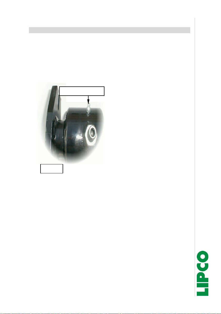
7. Preparation
•Lubricate drive flange at least once a month and then rotate
flange once to allow the grease to become distributed –make
sure the machine is running smoothly. (Fig. 1)
•Make sure that all screws are tightened and all elements are in
perfect working order!
•Remove drive flange once a year, clean and regrease it.
Fig. 1
Lubricating nipple

Instructions
Pathway weeder WP 60/75/90/100/125
10 - 20
120131-05-EN BA WP 60_75_90_100_125 / 29.06.2020
8. Connection to the engine-driven machine
Before attaching the machine flange (Fig. 3- Ref. A) corresponding to
the type of engine-driven machine you have, it is recommended
spreading grease on the outer diameter of the machine hub (Fig. 3,
Ref. B). Then fix the flange with its two threaded pins (Fig. 3, Ref. C)
and the two lock nuts. To attach the flange to the hub, proceed as
follows:
•Screw the threaded pins in as far as possible; when they have
struck the bottom, unscrew them by one turn. Tighten the lock
nuts. After this operation, make sure that the flange oscillates
freely without squeezing or blocking.
•After having greased the connecting shaft, insert it (Fig. 3, Ref.
D) on the machine shaft of the Pathway Weeder. When these
steps are complete, move the engine-driven machine close to
the unit. Ensure the toothed wheel work of the connecting shaft
engages correctly with the power takeoff shaft of the engine-
driven machine and the flange has a centered contact with the
engine-driven machine. Then connect the flange of the unit to
the engine-driven machine.
•Before commencing work, lubricate the drive flange (Fig. 2, Ref.
E).
A
Fig. 2
C
C
D
C
E
B

Instructions
Pathway weeder WP 60/75/90/100/125
11 - 20
120131-05-EN BA WP 60_75_90_100_125 / 29.06.2020
9. Adjustment of the working depth
The working depth is adjusted by
means of the spindle.
(Fig. 3)
It is important for the operator to leave
the machine resting on its roller while
working.
10. Working with the edge cutter
The edge cutter can be delivered as
special equipment.
In order to attach the edge cutter, a
short safety sheet must be attached to
the corresponding side of the machine,
and the safety bar must be removed.
The short safety sheet is included in
the delivery of the edge cutter.
(Fig. 4 with standard safety sheet and
guard strip for all work without edge
cutter, Fig. 6 with attached edge cutter)
Fig. 4
Safety bar
Standard
safety sheet
Fig. 3

Instructions
Pathway weeder WP 60/75/90/100/125
12 - 20
120131-05-EN BA WP 60_75_90_100_125 / 29.06.2020
For any work without edge cutter, the standard safety sheet must be
attached in addition to the safety bar.
(Fig. 7)
Height adjustment of the edge cutter by
means of manual spindle
Standard safety sheet
Safety bar
Fig. 7
Fig. 6
Short safety sheet
Instructions
Pathway weeder WP 60/75/90/100/125
13 - 20
120131-05-EN BA WP 60_75_90_100_125 / 29.06.2020
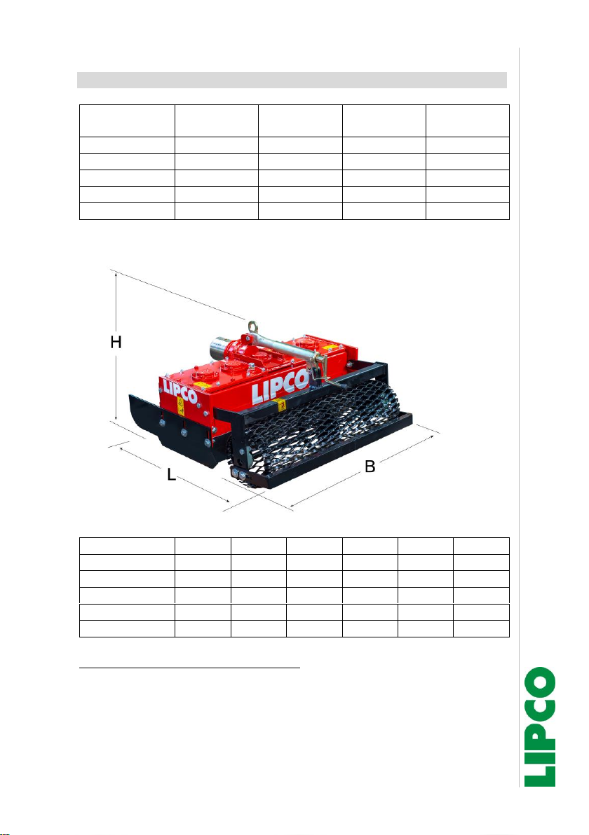
11. Technical data
Type
Weight
(kg)
Required
power (KW)
Tools (pcs.)
WP 60
90
5
6
WP 75
110
6
10
WP 90
140
7
10
WP 100
155
8
14
WP 125
170
10,5
14
Main dimensions
L
B
H
WP 60
780
600
460
WP 75
780
750
460
WP 90
780
900
460
WP 100
780
1000
460
WP 125
750
1250
460
Remarks about noise and vibration:
It is not expected, that the values for noise and vibration of these
attachment unit will exceed the values of the engine-driven machine.

Instructions
Pathway weeder WP 60/75/90/100/125
14 - 20
120131-05-EN BA WP 60_75_90_100_125 / 29.06.2020
12. Maintenance
Steps to be carried out in order to maintain the machine in good
working condition:
•Grease the roller bearings! (Fig. 8)
•Check the level of liquid grease in the gear casing via the
corresponding plug (Fig. 9). To do so, the machine hood must be
dismounted. This operation must be carried out when the
machine has already been running for a few minutes and the
grease has warmed up and become distributed evenly. Then
check the grease level with a dipstick (grease level should be 2.5
cm). This lubrication is a long-term lubrication (liquid gear grease
based on sodium bicarbonate, type GP00).
•Grease the drive flange at least once a month using the
lubricating nipple especially provided for this purpose! (Fig. 1)
•Remove drive flange once a year, clean and regrease it.
Filler neck
Fig. 9
Fig. 8
Lubricating nipple

Instructions
Pathway weeder WP 60/75/90/100/125
15 - 20
120131-05-EN BA WP 60_75_90_100_125 / 29.06.2020
Filling amount liquid gear grease type
GP00
Machine type
Amount (kg)
WP 60
2.8
WP 75
4.3
WP 90
4.8
WP 100
6.0
WP 125
7.0
•Check whether the tools have been firmly tightened, and
retighten the screws, if necessary. Replace damaged screws or
tools immediately!
(See chapter “13. Replacement of the tools”)

Instructions
Pathway weeder WP 60/75/90/100/125
16 - 20
120131-05-EN BA WP 60_75_90_100_125 / 29.06.2020
13. Replacement of the tools
When replacing the tools, make sure that the machine is secured
against unintentional tilting! When working with the unit lifted, always
ensure mechanical protection by means of adequate supporting
elements.
When attaching the tool holders, make sure the lock nuts engage
firmly in the recesses, to prevent them from turning and getting
damaged when loosening or tightening the screws. Also tighten the
screws for the attachment of the tools; when doing so, make sure the
tools are fixed correctly in the recesses provided for this purpose.
Note: When replacing the tools, always replace screws and
lock nuts as well, and only use original screws!

Instructions
Pathway weeder WP 60/75/90/100/125
17 - 20
120131-05-EN BA WP 60_75_90_100_125 / 29.06.2020
14. After use
If the LIPCO Pathway Weeder
is to remain unused for a longer
period, it is necessary to carry out the following steps:
•Thoroughly wash and dry the LIPCO Pathway Weeder!
•Check the function of all movable parts. Replace damaged or
worn parts!
•Check whether all screws are tightened!
•Check the oil and lubricant levels!
•Grease all unpainted metal parts to protect them against
corrosion, cover the LIPCO Pathway Weeder and store it in a dry
place so that it will be ready for use any time.
Attention! Before using the unit again, follow the instructions
in chapter "12. Maintenance".


Instructions
Pathway weeder WP 60/75/90/100/125
19 - 20
120131-05-EN BA WP 60_75_90_100_125 / 29.06.2020
16. EC Declaration of Conformity
Manufacturer
Person authorized to compile the
technical files:
LIPCO GmbH
Ingenieurbuero Bauer
Am Fuchsgraben 5b
Scherzinger Weg 46
77880 Sasbach
79227 Schallstadt
Germany
Germany
Tel.
: +49 7841 6348-0
Tel.
:+49 172 7694 903
Fax:
: +49 7841 6348-300
Fax:
e-mail
e-mail
website
: www.lipco.com
website
Denomination: LIPCO Pathway Weeder WP 60/75/90/100/125
Serial no:
Year of manufacture:
The manufacturer declares expressly, that the machinery fulfills all the
relevant provisions of the
•Directive 2006/42/EC
To implement the safety and health requirements as stated in the CE
Directive, the following standard(s) and/or technical specification(s) has
(have) been applied:
•DIN EN 709
•EN ISO 12100
•DIN EN ISO 4254-1 / DIN EN ISO 4254-5
This declaration of conformity loses its validity, if changes or modifications
on the machine were made, which are not approved in writing before by
LIPCO.
Willi Lipp
- Technical director -
Sasbach, 2019.08.09
(Place and date of issue)
(Name, function and signature of responsible)

20 - 20
Design: mail@bauer-ib.com
This manual suits for next models
4
Table of contents
Other Lipco Farm Equipment manuals


Popular Farm Equipment manuals by other brands

J&M
J&M 1522 Operator's manual

Cumberland
Cumberland Integra Feed-Link Installation and operation manual

BROWN
BROWN BDHP-1250 Owner's/operator's manual

Ashland
Ashland HDW-3217-12 parts manual

SKY Agriculture
SKY Agriculture 20 Series Original instructions

HE-VA
HE-VA Combi-Disc Series Operating Instructions, Spare parts list, Declaration of Conformity

MASCAR
MASCAR Diavel 630 Use and maintenance manual

Roxell
Roxell Swii'Flo user guide

Rain Harvesting
Rain Harvesting Clean Rain Ultra Installation and specification guide

Demco
Demco 1122 Operator's manual

Kerbl
Kerbl Air Buddex Instructions for use

AGCO
AGCO FENDT 700 Vario SCR Stage 3B Workshop service manual


