Best Buy BE-MLFM User manual

Large Full Motion Mount for 47" - 84"
TVs
User Guide
BE-MLFM
/Before using your new product, please read these instructions to prevent any damage.
Avant l’utilisation de ce produit neuf, lire ces instructions afin d'éviter tout dommage.
Large Full Motion Mount
for 47–84" TVs /
Soporte grande de movimiento
completo para televisores
de 47 a 84 pulg.
User Guide / Guía de usario
BE-MLFM
ENGLISH . . . . . . . . . . . . . . . . . . . . . . . .3
ESPAÑOL . . . . . . . . . . . . . . . . . . . . . . 19

2
Contents
ENGLISH . . . . . . . . . . . . . . . . . . . . . . . . . . . . . . . . . . . . . . . . . . . . . . . . . . . . . . . . . . . . . . . . . . . . . . . . . . . . . . . . 3
IMPORTANT SAFETY INSTRUCTIONS . . . . . . . . . . . . . . . . . . . . . . . . . . . . . . . . . . . . . . . . . . . . . . . . . . . . . . . . . . . . 3
Features . . . . . . . . . . . . . . . . . . . . . . . . . . . . . . . . . . . . . . . . . . . . . . . . . . . . . . . . . . . . . . . . . . . . . . . . . . . . . . . . . . . . . . . 3
VESA TV screw hole patterns . . . . . . . . . . . . . . . . . . . . . . . . . . . . . . . . . . . . . . . . . . . . . . . . . . . . . . . . . . . . . . . . . . . . . . . . . . . . . . . . . 3
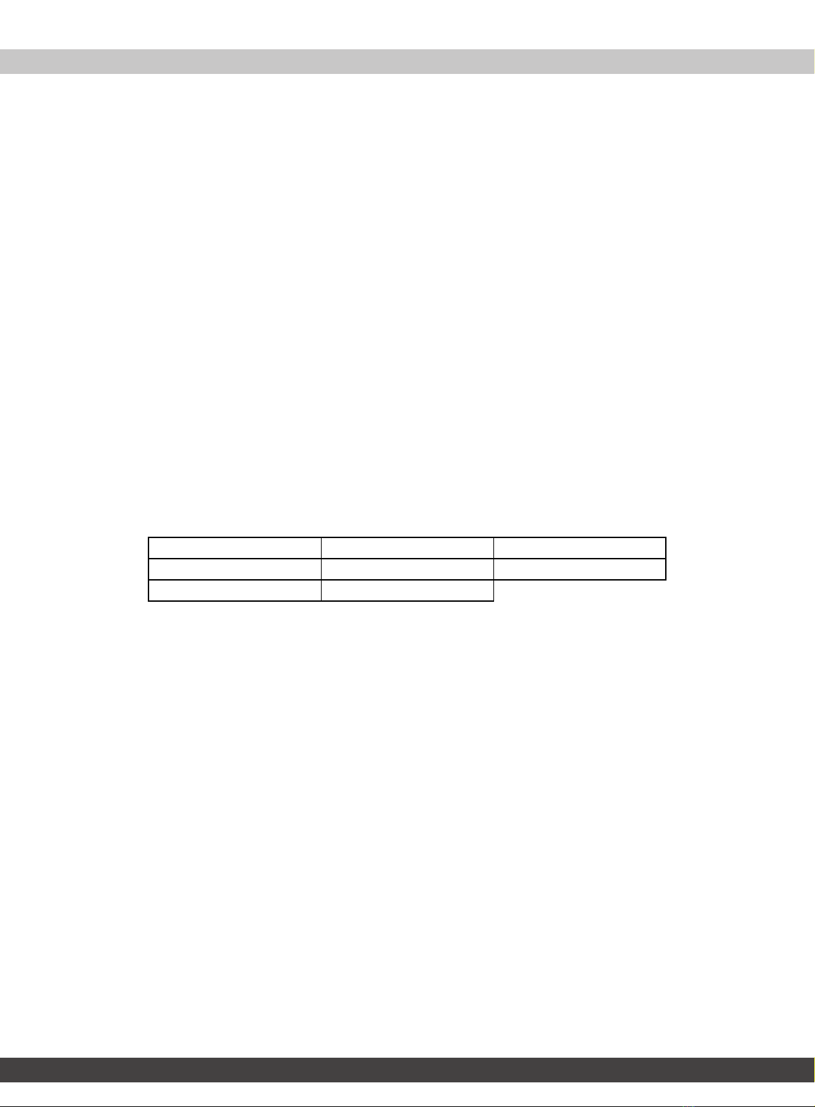
Dimensions. . . . . . . . . . . . . . . . . . . . . . . . . . . . . . . . . . . . . . . . . . . . . . . . . . . . . . . . . . . . . . . . . . . . . . . . . . . . . . . . . . . . . . . . . . . . . . . . . . 4
Tools needed . . . . . . . . . . . . . . . . . . . . . . . . . . . . . . . . . . . . . . . . . . . . . . . . . . . . . . . . . . . . . . . . . . . . . . . . . . . . . . . . . . 4
Package contents . . . . . . . . . . . . . . . . . . . . . . . . . . . . . . . . . . . . . . . . . . . . . . . . . . . . . . . . . . . . . . . . . . . . . . . . . . . . . . 5
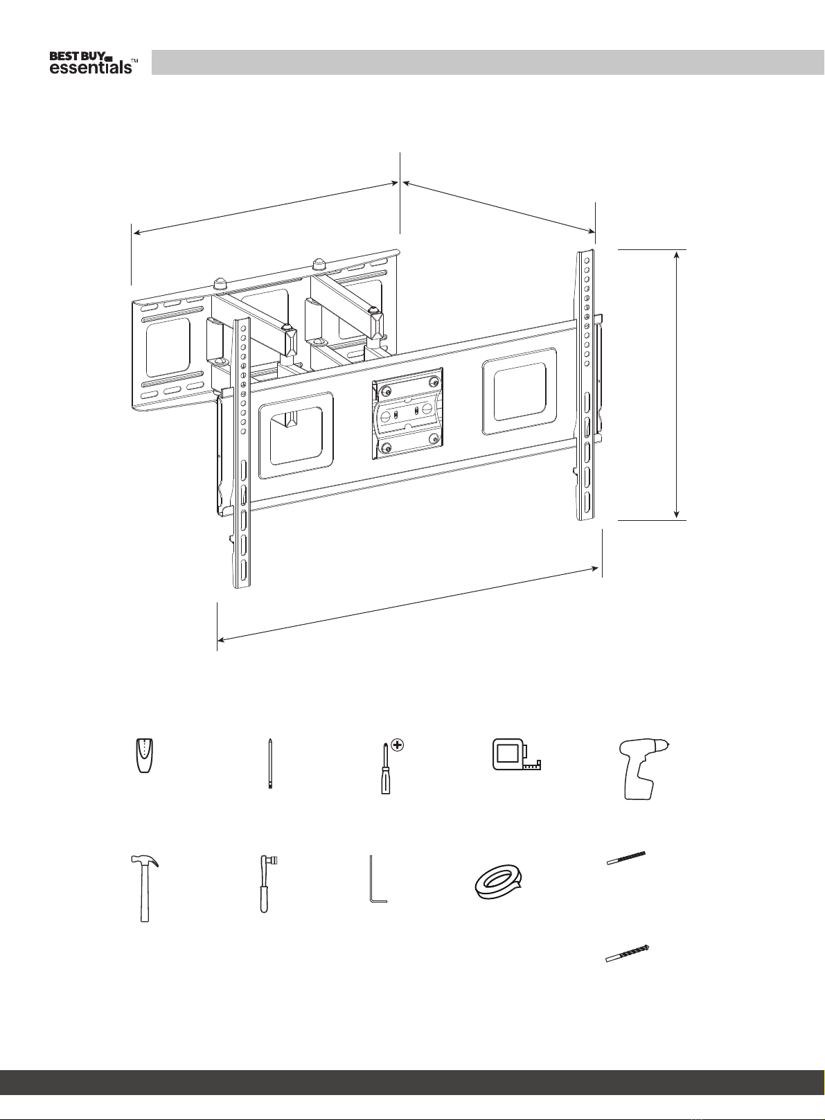
Parts . . . . . . . . . . . . . . . . . . . . . . . . . . . . . . . . . . . . . . . . . . . . . . . . . . . . . . . . . . . . . . . . . . . . . . . . . . . . . . . . . . . . . . . . . . . . . . . . . . . . . . . . 5
TV Hardware Bag . . . . . . . . . . . . . . . . . . . . . . . . . . . . . . . . . . . . . . . . . . . . . . . . . . . . . . . . . . . . . . . . . . . . . . . . . . . . . . . . . . . . . . . . . . . . 5
Installation instructions . . . . . . . . . . . . . . . . . . . . . . . . . . . . . . . . . . . . . . . . . . . . . . . . . . . . . . . . . . . . . . . . . . . . . . . . 6
STEP 1 - Determine whether your TV has a flat back or an irregular or obstructed back . . . . . . . . . . . . . . . . . . . . . . . . . 6
STEP 2 - Select screws, washers, and spacers . . . . . . . . . . . . . . . . . . . . . . . . . . . . . . . . . . . . . . . . . . . . . . . . . . . . . . . . . . . . . . . . . . 7
STEP 3 - Option 1: Attach the mounting hardware to a TV with a flat back. . . . . . . . . . . . . . . . . . . . . . . . . . . . . . . . . . . . . . 8
STEP 3 - Option 2: Attach the mounting hardware to a TV with an irregular or obstructed back . . . . . . . . . . . . . . . . . 9
STEP 4 - Determine the wall-mount location . . . . . . . . . . . . . . . . . . . . . . . . . . . . . . . . . . . . . . . . . . . . . . . . . . . . . . . . . . . . . . . . . 10
STEP 5 - Option 1: Install on a wood stud* wall . . . . . . . . . . . . . . . . . . . . . . . . . . . . . . . . . . . . . . . . . . . . . . . . . . . . . . . . . . . . . . . 11
STEP 5 - Option 2: Install on a solid concrete or concrete block wall . . . . . . . . . . . . . . . . . . . . . . . . . . . . . . . . . . . . . . . . . . . 13
STEP 6 - Secure your TV to the wall plate. . . . . . . . . . . . . . . . . . . . . . . . . . . . . . . . . . . . . . . . . . . . . . . . . . . . . . . . . . . . . . . . . . . . . 15
STEP 7 - Manage cables . . . . . . . . . . . . . . . . . . . . . . . . . . . . . . . . . . . . . . . . . . . . . . . . . . . . . . . . . . . . . . . . . . . . . . . . . . . . . . . . . . . . . 16
STEP 8 - Adjust the mount arm and tilt angles. . . . . . . . . . . . . . . . . . . . . . . . . . . . . . . . . . . . . . . . . . . . . . . . . . . . . . . . . . . . . . . . 17
ONE-YEAR LIMITED WARRANTY . . . . . . . . . . . . . . . . . . . . . . . . . . . . . . . . . . . . . . . . . . . . . . . . . . . . . . . . . . . . . . .18
ESPAÑOL . . . . . . . . . . . . . . . . . . . . . . . . . . . . . . . . . . . . . . . . . . . . . . . . . . . . . . . . . . . . . . . . . . . . . . . . . . . . . . .19
INSTRUCCIONES IMPORTANTES DE SEGURIDAD. . . . . . . . . . . . . . . . . . . . . . . . . . . . . . . . . . . . . . . . . . . . . . . .19
Características . . . . . . . . . . . . . . . . . . . . . . . . . . . . . . . . . . . . . . . . . . . . . . . . . . . . . . . . . . . . . . . . . . . . . . . . . . . . . . . .19
Patrones de agujeros de tornillos VESA para televisores . . . . . . . . . . . . . . . . . . . . . . . . . . . . . . . . . . . . . . . . . . . . . . . . . . . . . . 19
Dimensiones . . . . . . . . . . . . . . . . . . . . . . . . . . . . . . . . . . . . . . . . . . . . . . . . . . . . . . . . . . . . . . . . . . . . . . . . . . . . . . . . . . . . . . . . . . . . . . . 20
Herramientas requeridas . . . . . . . . . . . . . . . . . . . . . . . . . . . . . . . . . . . . . . . . . . . . . . . . . . . . . . . . . . . . . . . . . . . . . .20
Contenido del paquete . . . . . . . . . . . . . . . . . . . . . . . . . . . . . . . . . . . . . . . . . . . . . . . . . . . . . . . . . . . . . . . . . . . . . . .21
Elementos . . . . . . . . . . . . . . . . . . . . . . . . . . . . . . . . . . . . . . . . . . . . . . . . . . . . . . . . . . . . . . . . . . . . . . . . . . . . . . . . . . . . . . . . . . . . . . . . . . 21
Bolsa de accesorios para televisor . . . . . . . . . . . . . . . . . . . . . . . . . . . . . . . . . . . . . . . . . . . . . . . . . . . . . . . . . . . . . . . . . . . . . . . . . . . 21
Instrucciones de instalación . . . . . . . . . . . . . . . . . . . . . . . . . . . . . . . . . . . . . . . . . . . . . . . . . . . . . . . . . . . . . . . . . . .22
PASO 1 - Determine si su televisor tiene una parte posterior plana, irregular u obstruida . . . . . . . . . . . . . . . . . . . . . . 22
PASO 2 - Selección de los tornillos, arandelas y espaciadores . . . . . . . . . . . . . . . . . . . . . . . . . . . . . . . . . . . . . . . . . . . . . . . . . 23
PASO 3 - Opción 1: Instalación de la ferretería de montaje para televisor con una parte posterior plana . . . . . . . . 24
PASO 3 - Opción 2: Instalación de la tornillería de montaje en un televisor con la parte posterior irregular u
obstruida. . . . . . . . . . . . . . . . . . . . . . . . . . . . . . . . . . . . . . . . . . . . . . . . . . . . . . . . . . . . . . . . . . . . . . . . . . . . . . . . . . . . . . . . . . 25
PASO 4 - Determine la ubicación del montaje en pared . . . . . . . . . . . . . . . . . . . . . . . . . . . . . . . . . . . . . . . . . . . . . . . . . . . . . . 27
PASO 5 - Opción 1: Instalación en una pared con viga de madera*. . . . . . . . . . . . . . . . . . . . . . . . . . . . . . . . . . . . . . . . . . . . 28
PASO 5 - Opción 2: Instalación en una pared de concreto sólido o de bloques de concreto . . . . . . . . . . . . . . . . . . . . 30
PASO 6 - Fije el televisor a la placa para pared. . . . . . . . . . . . . . . . . . . . . . . . . . . . . . . . . . . . . . . . . . . . . . . . . . . . . . . . . . . . . . . . 32
PASO 7 - Organización de los cables . . . . . . . . . . . . . . . . . . . . . . . . . . . . . . . . . . . . . . . . . . . . . . . . . . . . . . . . . . . . . . . . . . . . . . . . . 33
PASO 8 - Ajuste el brazo de montaje y los ángulos de inclinación . . . . . . . . . . . . . . . . . . . . . . . . . . . . . . . . . . . . . . . . . . . . . 34
GARANTÍA LIMITADA DE UN AÑO . . . . . . . . . . . . . . . . . . . . . . . . . . . . . . . . . . . . . . . . . . . . . . . . . . . . . . . . . . . . .35

3
Large Full Motion Mount for 47" - 84" TVs / Soporte grande de movimiento completo para televisores de 47 a 84 pulg.
www.bestbuy.com/bestbuyessentials
ENGLISH
IMPORTANT SAFETY INSTRUCTIONS
SAVE THESE INSTRUCTIONS
CAUTION: Do not use this product for any purpose not explicitly specified by BEST BUY ESSENTIALS.
• Improper installation may cause property damage or personal injury. If you do not understand these directions, or have
doubts about the safety of the installation, contact Customer Service or call a qualified contractor. Best Buy Essentials is
not responsible for damage or injury caused by incorrect installation or use.
• The weight of your TV must not exceed 110 lbs. (50 kg). The wall must be capable of supporting five times the weight of
your TV and wall mount combined.
• This product contains small items that could be a choking hazard if swallowed. Keep these items away from young
children!
Features
• Supports TVs from 47-84" and up to 110 lbs. (50 kg)
• Mounts to VESA patterns from 200 × 200 to 600 × 400 (with all common sizes in between)
• Center your TV with our lateral shift capability
• Adjust the viewing angle by swiveling and tilting
• Years of dependable use with our sturdy steel construction
• Built and backed by Best Buy
VESA TV screw hole patterns
Your wall mount works with the following VESA TV screw hole patterns:
200 × 200 mm (7.9 × 7.9") 400 × 200 mm (15.7 × 7.9") 500 × 400 mm (19.7 × 15.7")
300 × 200 mm (11.8 × 7.9") 400 × 300 mm (15.7 × 11.8") 600 × 400 mm (23.6 × 15.7")
300 × 300 mm (11.8 × 11.8") 400 × 400 mm (15.7 × 15.7")

4
BE-MLFM
www.bestbuy.com/bestbuyessentials
Dimensions
Tools needed
You need the following tools to assemble your new TV wall mount:
26.1 in. (66.4 cm)
18.1 in. (46 cm)
16.9 in.
(43 cm)
18 in. (45.7 cm)
Edge-to-edge stud
finder Phillips screwdriver
Measuring tape
Drill
3/16 in. (5 mm) wood drill bit
(for wood stud wall)
Hammer
Tape
Pencil
Socket wrench 5 × Allen wrench OR
3/8 in. (10 mm) masonry drill
bit (for concrete wall)

5
Large Full Motion Mount for 47" - 84" TVs / Soporte grande de movimiento completo para televisores de 47 a 84 pulg.
www.bestbuy.com/bestbuyessentials
Package contents
Parts
Make sure that you have all the parts and hardware necessary to assemble your new TV wall mount:
TV Hardware Bag
LABEL HARDWARE QTY. LABEL HARDWARE QTY.
A1 4A10 4
A2 4A11 4
A3 4A12 4
A4 4A13 4
A5 4B1 4
A6 4B2 4
A7 4B3 4
A8 41
A9 43
Wall Mount
Wall Mount Template
TV Brackets (2)
M4 × 12 mm screw
M8 × 50 mm screw
M4 × 30 mm screw
Spacer
M5 × 12 mm screw
M4/M5 washer
M5 × 30 mm screw
M6/M8 washer
M6 × 12 mm screw
Lag bolt
M6 × 20 mm screw
Concrete anchor
M6 × 35 mm screw
Lag bolt washer
M8 × 16 mm screw
Magnetic removable bubble
level
M8 × 25 mm screw
Cable holder

6
BE-MLFM
www.bestbuy.com/bestbuyessentials
Installation instructions
STEP 1 - Determine whether your TV has a flat back or an irregular or obstructed back
1Carefully place your TV screen face-down on a cushioned, clean surface to protect the screen from damages and
scratches.
2If your TV has a table-top stand attached, remove the stand. See the documentation that came with your TV for
instructions.
3Lay the TV brackets, oriented vertically, on the back of your TV.
4Align the screw holes in the TV brackets with the mounting screw holes on your TV.
5Identify which type of back your TV has:
•Flat back: The brackets lay flush against the back of your TV and do not block any jacks. You do not need spacers when
assembling the wall mount.
•Obstructed back: The brackets block one or more of the jacks on the back of your TV. You need spacers when
assembling the wall mount.
•Irregularly-shaped back: There is a gap between a bracket and some part of the back of your TV. You need spacers
when assembling the wall mount.
6Remove the TV brackets.

7
Large Full Motion Mount for 47" - 84" TVs / Soporte grande de movimiento completo para televisores de 47 a 84 pulg.
www.bestbuy.com/bestbuyessentials
STEP 2 - Select screws, washers, and spacers
1Select the hardware for your TV (screws, washers, and spacers). A limited number of TVs come with mounting hardware
included. (If there are screws that came with your TV, they are almost always in the holes on the back of your TV.) If you
don't know the correct length of the mounting screws your TV requires, test various sizes by hand-threading the
screws.
Select one of the following types of screws:
For a TV with a flat back:
• M4 X 12 mm screws (A1)
• M5 X 12 mm screws (A3)
• M6 X 12 mm screws (A5)
• M8 X 16 mm screws (A8)
For a TV with an irregular/obstructed back:
• M4 X 30 mm screws (A2)
• M5 X 30 mm screws (A4)
• M6 X 20 mm screws (A6)
• M6 X 35 mm screws (A7)
• M8 X 25 mm screws (A9)
• M8 X 50 mm screws (A10)
If you use M4 or M5 screws, select the M4/M5 washer (A12) or if you use M6 or M8 screws, select the
M6/M8 washer (A13). For an irregular or obstructed TV back, also use the spacers (A11).
2Remove the screws from the holes in the back of your TV.
3For a flat back TV, go to STEP 3 - Option 1: Attach the mounting hardware to a TV with a flat back on page 8.
-OR-
For an irregular or obstructed back, go to STEP 3 - Option 2: Attach the mounting hardware to a TV with an irregular or
obstructed back on page 9.
CAUTION: To avoid potential personal injuries and property damage, make sure that there are adequate threads to secure the
brackets to your TV. If you encounter resistance, stop immediately and contact customer service. Use the shortest screw and spacer
combination to accommodate your TV. Using hardware that is too long may damage your TV. However, using a screw that is too short
may cause your TV to fall from the mount.
Screw is
too long
Screw fits
correctly
Screw is
too short

8
BE-MLFM
www.bestbuy.com/bestbuyessentials
STEP 3 - Option 1: Attach the mounting hardware to a TV with a flat back
You’ll need
1Align the left and right TV brackets with the screw holes on the back of your TV. Make sure that the brackets are level.
2Install washers (A12 or A13) and screws (A1, A3, A5, or A8) into the holes in the back of your TV.
3Tighten the screws until they are snug against your TV brackets. Do not over tighten.
A1 (4)
Phillips screwdriver
Screws Washers
TV brackets (2)
OR
A3 (4) A12 (4)
A5 (4)
Magnetic removable
bubble level
OR A13 (4)
OR
A8 (4)
OR
A12 or
A13 A1/A3/A5
or A8
TV brackets

9
Large Full Motion Mount for 47" - 84" TVs / Soporte grande de movimiento completo para televisores de 47 a 84 pulg.
www.bestbuy.com/bestbuyessentials
STEP 3 - Option 2: Attach the mounting hardware to a TV with an irregular or obstructed back
You’ll need
1Place spacers (A11) over the holes on the back of your TV.
2Align the left and right TV brackets with the screw holes on the back of your TV. Make sure that the brackets are level.
3Place washers (A12 or A13) over the holes in the TV brackets. Insert screws (A2, A4, A6, A7, A9, or A10) through the
washers, TV brackets, and spacers and into the screw holes on the back of your TV.
4Tighten the screws until they are snug against the TV brackets. Do not over tighten.
A2 (4) A4 (4)
Phillips screwdriver
Screws
A7 (4)
OR
A11 (4)
OR
Spacers
TV brackets (2)
A6 (4)
OR
OR
Washers
A12 (4) A13 (4)
OR
Magnetic removable
bubble level
A10 (4)
OR
A9 (4)
OR
OR
A12 or
A13 A2/A4 or
A6/A7 or
A9/A10
TV brackets
A11

10
BE-MLFM
www.bestbuy.com/bestbuyessentials
STEP 4 - Determine the wall-mount location
You’ll need
The center of your TV will be offset .8 in. lower than the center of the wall plate on the wall-mount. Before you drill holes in
the wall:
1Measure the distance from the bottom of your TV to the center point halfway between the top and bottom mounting
holes on the back of your TV. This is measurement a.
2Measure the distance from the floor to where you want the bottom of your TV to be placed on the wall. Keep in mind
that the bottom of your TV should be placed above any furniture (such as entertainment centers or TV stands). Your TV
should also be above items placed on top of the furniture (like a Blu-ray player or cable box). This measurement is b.
3Add a + b. The total measurement is the height where you want the center of the wall plate to be on the wall.
4Use a pencil to mark this spot on the wall.
Notes:
• For more detailed information on determining where to drill your holes, visit our online height-finder at:
http://mf1.bestbuy.selectionassistant.com/index.php/heightfinder
• Your TV should be high enough so your eyes are level with the middle of the screen. This is normally 40 to 60 in. from the ground.
Measuring tape
Pencil
A
B

11
Large Full Motion Mount for 47" - 84" TVs / Soporte grande de movimiento completo para televisores de 47 a 84 pulg.
www.bestbuy.com/bestbuyessentials
STEP 5 - Option 1: Install on a wood stud* wall
You’ll need
1Locate the stud. Verify the center of the stud with an edge-to-edge stud finder.
2Align the center of the wall plate template at the height (a + b) you determined in the previous step, make sure that the
template is level, then tape it to the wall.
3Drill four pilot holes through the template to a depth of 2.4 in. (60 mm) using a 3/16 in. (5 mm) diameter drill bit, then
remove the template.
Note: Any drywall covering the wall must not exceed 5/8 in. (16 mm).
Edge-to edge
stud finder Drill
3/16 in. wood
drill bit
Magnetic removable bubble
level
Wall plate template
Tape
B1 (4)
B3 (4)
Wall mount
Socket wrench
Align the center of the
template with the height
mark (a+b) you made in
STEP 4.
Level
* Minimum wood stud size: common 2 × 4 in. (51 × 102 mm) nominal 11/2 × 31/2 in. (38 × 89 mm).
* Minimum horizontal spacing between fasteners cannot be less than 16 in. (406 mm).
2.4 in. (60 mm)
3/16 in. (5 mm)

12
BE-MLFM
www.bestbuy.com/bestbuyessentials
4Align the wall plate on the wall mount with the pilot holes, insert the lag bolts (B1) through the lag bolt washers (B3),
then through the holes in the wall plate. Make sure that the wall plate is level. Tighten the lag bolts with a socket
wrench only until they are firm against the wall plate.
CAUTION: DO NOT over-tighten the lag bolts (B1).
B3 B1
Wood stud
Magnetic removable
bubble level

13
Large Full Motion Mount for 47" - 84" TVs / Soporte grande de movimiento completo para televisores de 47 a 84 pulg.
www.bestbuy.com/bestbuyessentials
STEP 5 - Option 2: Install on a solid concrete or concrete block wall
You’ll need
1Align the center of the wall plate template at the height (a + b) you determined in the previous step, make sure that it is
level, then tape it to the wall.
2Drill four pilot holes through the template to a depth of 2.4 in. (60 mm) using a 3/8 in. (10 mm) diameter masonry drill
bit, then remove the template.
CAUTION: To prevent property damage or personal injury, never drill into the mortar between blocks. Mount the wall
plate directly onto the concrete surface.
3/8 in.
masonry drill
bit
Wall plate template
B2 (4)
Hammer
B1 (4)
B3 (4)
Wall mount
Magneticremovable
bubble level
Socket wrench Drill
Edge-to edge
stud finder Tape
* Minimum solid concrete thickness: 8 in. (203mm)
* Minimum concrete block size: 8 x 8 x 16 in. (203 x 203 x 406 mm).
* Minimum horizontal spacing between fasteners cannot be less than 16 in. (406 mm).
2.4 in. (60 mm)
3/8 in. (10 mm)
Align the center of
the template with
the height mark
(a+b) you made in
STEP 4.

14
BE-MLFM
www.bestbuy.com/bestbuyessentials
3Insert the concrete wall anchors (B2) into the pilot holes and use a hammer to make sure that the anchors are flush with
the concrete surface.
4Align the wall plate on the wall mount with the anchors, insert the lag bolts (B1) through the lag bolt washers (B3),
then through the holes in the wall plate. Make sure that the wall plate is level. Tighten the lag bolts with a socket
wrench only until they are firm against the wall plate.
.
CAUTION: DO NOT over-tighten the lag bolts (B1).
Concrete wall
B2
B3
B1
Magnetic removable
bubble level

15
Large Full Motion Mount for 47" - 84" TVs / Soporte grande de movimiento completo para televisores de 47 a 84 pulg.
www.bestbuy.com/bestbuyessentials
STEP 6 - Secure your TV to the wall plate
You’ll need
1Holding your TV with the top of the screen tilted toward the wall, slide the upper edges of the right and left TV brackets
into the notches on the upper lip of your TV wall plate.
2Push the bottom of your TV toward the wall until the safety bolts click into place, then tighten the bolts with a Phillips
screw driver.
CAUTION: Do not release your TV until the TV brackets are securely locked onto the wall plate.
Phillips screwdriver
HEAVY! You will
need assistance
with this step.
Safety bolt

16
BE-MLFM
www.bestbuy.com/bestbuyessentials
STEP 7 - Manage cables
You’ll need
• Thread cables for attached devices along the mounting arm, then snap the cable holders over the cables to hold them
in place.
Cable holder (3)
Cable holder
Cables

17
Large Full Motion Mount for 47" - 84" TVs / Soporte grande de movimiento completo para televisores de 47 a 84 pulg.
www.bestbuy.com/bestbuyessentials
STEP 8 - Adjust the mount arm and tilt angles
You’ll need
1To adjust the arms’tension (to make the arm easier or harder to move), loosen or tighten the tension screws with an
Allen wrench.
2To rotate your TV left or right, hold the sides of your TV, then push one side while pulling the other side.
3To tilt of your TV up or down, hold the top and bottom of your TV, then tilt your TV forward or backward.
4If the TV screen sags, tighten the two bolts (shown below) on the TV plate with a socket wrench until they are snug.
Allen wrench Socket wrench
Allen wrench
Tension screw
Tension
screw
-8° ~ 12°
45°
TV

18
BE-MLFM
www.bestbuy.com/bestbuyessentials
ONE-YEAR LIMITED WARRANTY
Definitions:
The Distributor* of Best Buy Essentials branded products warrants to you, the original purchaser of this new Best Buy Essentials-branded product (“Product”),
that the Product shall be free of defects in the original manufacturer of the material or workmanship for a period of one (1) year from the date of your purchase
of the Product (“Warranty Period”).
For this warranty to apply, your Product must be purchased in the United States or Canada from a Best Buy branded retail store or online at www.bestbuy.com
or www.bestbuy.ca and is packaged with this warranty statement.
How long does the coverage last?
The Warranty Period lasts for 1 year (365 days) from the date you purchased the Product. Your purchase date is printed on the receipt you received with the
Product.
What does this warranty cover?
During the Warranty Period, if the original manufacture of the material or workmanship of the Product is determined to be defective by an authorized Best Buy
Essentials repair center or store personnel, Best Buy Essentials will (at its sole option): (1) repair the Product with new or rebuilt parts; or (2) replace the Product
at no charge with new or rebuilt comparable products or parts. Products and parts replaced under this warranty become the property of Best Buy Essentials
and are not returned to you. If service of Products or parts are required after the Warranty Period expires, you must pay all labor and parts charges. This
warranty lasts as long as you own your Best Buy Essentials Product during the Warranty Period. Warranty coverage terminates if you sell or otherwise transfer
the Product.
How to obtain warranty service?
If you purchased the Product at a Best Buy retail store location or from a Best Buy online website (www.bestbuy.com or www.bestbuy.ca), please take your
original receipt and the Product to any Best Buy store. Make sure that you place the Product in its original packaging or packaging that provides the same
amount of protection as the original packaging.
To obtain warranty service, in the United States and Canada call 1-866-597-8427. Call agents may diagnose and correct the issue over the phone.
Where is the warranty valid?
This warranty is valid only in the United States and Canada at Best Buy branded retail stores or websites to the original purchaser of the product in the country
where the original purchase was made.
What does the warranty not cover?
This warranty does not cover:
REPAIR REPLACEMENT AS PROVIDED UNDER THIS WARRANTY IS YOUR EXCLUSIVE REMEDY FOR BREACH OF WARRANTY. BEST BUY ESSENTIALS SHALL NOT BE
LIABLE FOR ANY INCIDENTAL OR CONSEQUENTIAL DAMAGES FOR THE BREACH OF ANY EXPRESS OR IMPLIED WARRANTY ON THIS PRODUCT, INCLUDING, BUT
NOT LIMITED TO, LOST DATA,LOSS OF USE OF YOUR PRODUCT, LOST BUSINESS OR LOST PROFITS. BEST BUY ESSENTIALS PRODUCTS MAKES NO OTHER EXPRESS
WARRANTIES WITH RESPECT TO THE PRODUCT, ALL EXPRESS AND IMPLIED WARRANTIES FOR THE PRODUCT, INCLUDING BUT NOT LIMITED TO ANY IMPLIED
WARRANTIES OF AND CONDITIONS OF MERCHANTABILITY AND FITNESS FOR A PARTICULAR PURPOSE, ARE LIMITED IN DURATION TO THE WARRANTY PERIOD
SET FORTH ABOVE AND NO WARRANTIES, WHETHER EXPRESS OR IMPLIED, WILL APPLY AFTER THE WARRANTY PERIOD. SOME STATES, PROVINCES AND
JURISDICTIONS DO NOT ALLOW LIMITATIONS ON HOW LONG AN IMPLIED WARRANTY LASTS, SO THE ABOVE LIMITATION MAY NOT APPLYTO YOU. THIS
WARRANTY GIVES YOU SPECIFIC LEGAL RIGHTS, AND YOU MAY ALSO HAVE OTHER RIGHTS, WHICH VARY FROM STATETO STATE OR PROVINCE TO PROVINCE.
Contact Best Buy Essentials:
1-866-597-8427
www.bestbuy.com/bestbuyessentials
BEST BUY ESSENTIALS is a trademark of Best Buy and its affiliated companies.
*Distributed by Best Buy Purchasing, LLC
7601 Penn Ave South, Richfield, MN 55423 U.S.A.
©2021 Best Buy. All rights reserved.
• Customer instruction/education
• Installation
•Setupadjustments
• Cosmetic damage
• Damage due to weather, lightning, and other acts of God, such as
power surges
•Accidentaldamage
•Misuse
•Abuse
•Negligence
• Commercial purposes/use, including but not limited to use in a place
of business or in communal areas of a multiple dwelling condominium
or apartment complex, or otherwise used in a place of other than a
private home.
• Modification of any part of the Product, including the antenna
• Display panel damaged by static (non-moving) images applied for
lengthy periods (burn-in).
• Damage due to incorrect operation or maintenance
• Connection to an incorrect voltage or power supply
• Attempted repair by any person not authorized by Best Buy Essentials
to service the Product
• Products sold "as is" or "with all faults"
• Consumables, including but not limited to batteries (i.e. AA, AAA, C
etc.)
• Products where the factory applied serial number has been altered or
removed
• Loss or Theft of this product or any part of the product
• Display panels containing up to three (3) pixel failures (dots that are
dark or incorrectly illuminated) grouped in an area smaller than one
tenth (1/10) of the display size or up to five (5) pixel failures throughout
the display. (Pixel based displays may contain a limited number of
pixels that may not function normally.)
• Failures or Damage caused by any contact including but not limited to
liquids, gels or pastes.

19
Large Full Motion Mount for 47" - 84" TVs / Soporte grande de movimiento completo para televisores de 47 a 84 pulg.
www.bestbuy.com/bestbuyessentials
ESPAÑOL
INSTRUCCIONES IMPORTANTES DE SEGURIDAD
GUARDE ESTAS INSTRUCCIONES
ADVERTENCIA: No utilice este producto con cualquier propósito que no esté explícitamente especificado por BEST BUY
ESSENTIALS.
• Una instalación inadecuada podría causar daños materiales o lesiones personales. Si no comprende estas instrucciones,
o tiene dudas sobre la seguridad de la instalación, póngase en contacto con Servicio al cliente o llame a un contratista
calificado Best Buy Essentials no se hace responsable por daños o lesiones causadas por una instalación o uso
incorrecto.
• El peso de su televisor no debe exceder 110 lb. (50 kg). La pared debe ser capaz de soportar cinco veces el peso de su
televisor, incluyendo el montaje de pared.
• Este producto contiene piezas pequeñas que representan un peligro de asfixia si se tragan. ¡Mantenga estas piezas
alejadas de los niños!
Características
• Aguanta televisores de 47 a 84 pulg. y de hasta 110 lb (50 kg)
• Compatible con patrones VESA desde 200 × 200 hasta 600 × 400 (con todos los tamaños comunes entre ellos)
• Centre su televisor con nuestra capacidad de desplazamiento lateral
• Ajuste el ángulo de visión mediante el giro y la inclinación
• Años de uso confiable con nuestra robusta construcción de acero
• Construido y respaldado por Best Buy
Patrones de agujeros de tornillos VESA para televisores
Su soporte de pared funciona con los siguientes patrones de orificios para tornillos VESA para televisores:
200 × 200 mm (7.9 × 7.9 pulg.) 400 × 200 mm (15.7 × 7.9 pulg.) 500 × 400 mm (19.7 × 15.7 pulg.)
300 × 200 mm (11.8 × 7.9 pulg.) 400 × 300 mm (15.7 × 11.8 pulg.) 600 × 400 mm (23.6 × 15.7 pulg.)
300 × 300 mm (11.8 × 11.8 pulg.) 400 × 400 mm (15.7 × 15.7 pulg.)

20
BE-MLFM
www.bestbuy.com/bestbuyessentials
Dimensiones
Herramientas requeridas
Necesitará las siguientes herramientas para ensamblar su montaje de pared nuevo para el televisor:
26.1 pulg. (66.4 cm)
18.1 pulg. (46 cm)
16.9 pulg.(43
cm)
18 pulg. (45.7 cm)
Detector de vigas de
borde a borde Destornillador
Phillips
Cinta métrica
Taladro
Broca de taladro para madera de
3/16 pulg. (5 mm)
(para pared con vigas de madera)
Martillo
Cinta adhesiva
Lápiz
Llave de tubo Llave Allen 5 × O
Broca de taladro para concreto de 3/8
pulg. (10 mm) para pared de concreto
This manual suits for next models
1
Table of contents
Languages:
Other Best Buy TV Mount manuals