Best Data 56SX-92 User manual

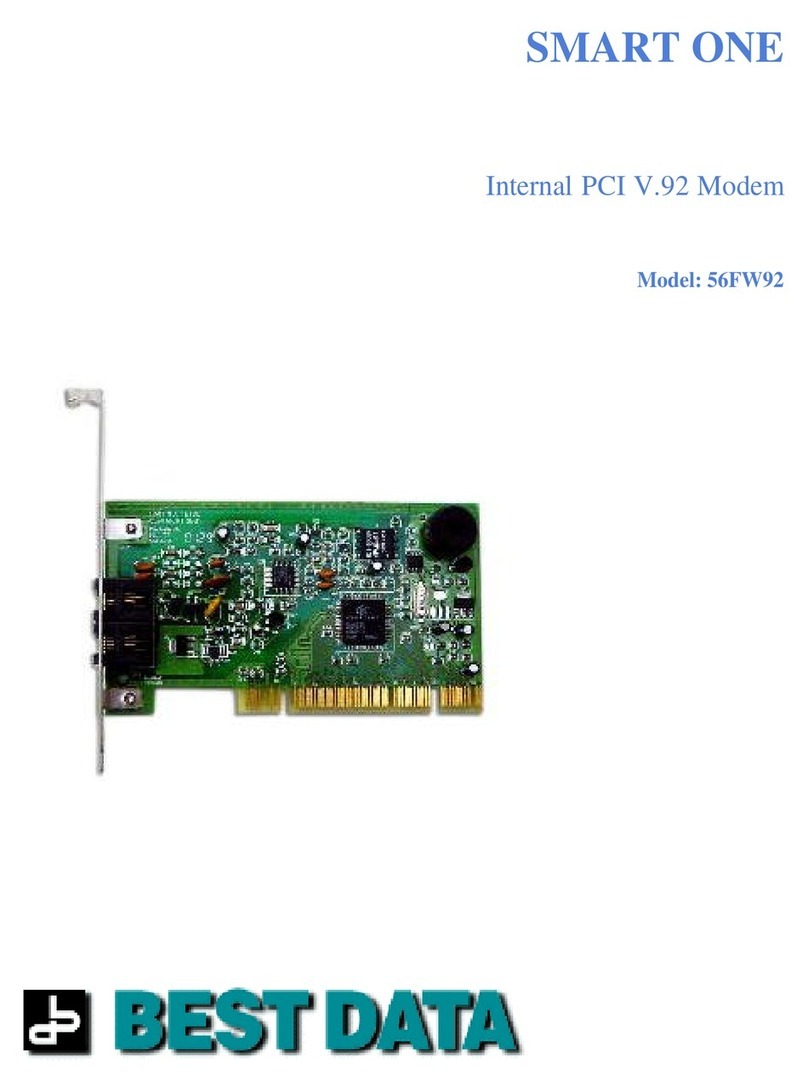
56SX-92 Serial Modem
Installation Guide
©2004 Best Data Products, Inc. All rights reserved. p/n 50017


Page 1
Package Contents
1 56SX-92 rev2 Modem
1 Installation Guide
1 Installation CD
1 AC Power Adapter
1 RS-232 Serial Cable
1 RJ-11 Telephone Cable
1 Warranty Card
56SX-92 rev2 Serial Modem
Safety Notices
•Do not connect or disconnect any cables or perform
installation, maintenance, or reconfiguration of this
product during an electrical storm.
•The power cord must be connected to a properly wired
and earthed (grounded) receptacle.
•Discharge static electricity from your body before you
touch this product. You can do so by touching the
unpainted back part of your computer chassis.
Please make sure to read all the instructions
thoroughly before attempting the installation of
this modem.
System Requirements
486 or higher class CPU
Windows 95, 98, ME, 2000, XP
Available 9-pin serial port
CD-ROM Drive
32MB hard disk space (fax software)
1MB hard disk space (modem driver)
32MB RAM

page 2
56SX-92 PRE-INSTALLATION
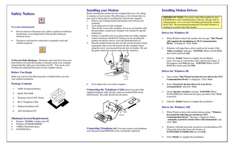
Before installing this modem it is very important to make sure that you have an
available serial port on your computer. Follow through the pre-installation steps
to ensure your serial port has been properly enabled.
1. Turn on the power to your computer and wait for the Windows
desktop to appear.
2. Right click the My Computer icon and left click Properties.
3a. For Users of Windows 95/98/ME
(If you are running Windows 2000 or XP please go to step 3b.)
Left click the Device Manager tab.

page 3
3b. For Users of Windows 2000/XP
Left click the Hardware tab. Left click the Device Manager button.
4. From the Device Manager left click the +symbol next to Ports.
NOTE If you do not have a Ports section then you will need to enable a
serial port in your system BIOS (CMOS). Please refer to the
warning icon at the bottom of this page.
5. The serial port you plan to conect the modem to should be visible from
within the Ports section that you opened in the previous step. The port
will appear as either Communications Port (COM1) or Communications
Port (COM2).
NOTE If you do not have a communications ports listed within the Ports
section you will need to enable a serial port in your
system CMOS. Refer to the warning icon at the bottom of this
page.
Please continue to page 5 for Hardware Installation.
If you need to enter your system CMOS to enable a serial port, please
refer to your system manufacturer’s instructions for using their CMOS.
Please refer to the next page for generic CMOS instructions to verify
that your serial port is enabled.

page 4
VERIFY SERIAL PORT IS ENABLED
Note This step only needs to be performed if you had referred to the
warning icon on the previous page.
The system BIOS (known as CMOS) is usually entered at the start of the boot
process by pressing a key or sequence of keys to get to the system setup
screens. Each system manufacturer uses different key combinations for
entering the CMOS/BIOS setup. Please refer to your system documentation
for specific key sequences for all of the following examples.
The key needed to be pressed to enter CMOS setup can be seen at the start of
the boot process (though it does not remain on the screen for very long) on
most systems.
Example: <PRESS F2 TO ENTER SETUP>
Common keys on some systems include: DEL, F1, F2, CTRL-ALT-S or ESC. Please
refer to your system manufacturers documentation for exact instructions to
enter the CMOS setup.
1. Turn on the power to the computer and enter your CMOS setup.
2. The serial ports will usually be listed within a Peripheral Configuration
or On Board Devices section. Consult your system documentation for
specifics and select the correct section for the serial ports.
Within this section the serial ports will be listed as either On Board Serial
Port 1 & 2 (or A and B) or On Board UART 1 & 2 (or A and B). Refer to
the examples below.
Examples: On Board Serial Port 1: 3F8h (COM1), IRQ4
On Board Serial Port 2: 2F8h (COM2), IRQ3
The serial port should not be set for DISABLED or AUTO. If the
serial port is set for DISABLED or AUTO you will need to change the
configuration. Please refer to your system manufacturer’s documentation
for the specific keys needed for this operation.
Your screen will normally show you a legend of which keys perform which
actions, usually located at the bottom of the CMOS screen.
3. Navigate the cursor to the correct serial port.
4. Change or modify the value to show either:
COM1 or 3F8h or 3F8
OR
COM2 or 2F8h or 2F8
5. Look for the option to save and exit CMOS. This will be the F10 key on
most systems. Please consult your system documentation for specific key
commands.
This concludes the CMOS setup to verify a serial port is enabled.

page 5
HARDWARE INSTALLATION
1. Locate an available serial port on the back of the computer. The serial port
will have 9 pins inside of the connector. Refer to the diagram below.
Sample Serial Port
2. Using the serial cable provided, connect the female end of the cable into
the serial port that you located in step 1. Refer to the diagram below.
3. Connect the male end of the serial cable into the female connector on the
back of the modem. Refer to the diagram below.
Serial Cable Female Connector
Male Connector Connect to Serial Port on the modem
4. Using the AC adapter provided with the modem, connect the small round
connector on one end of the adapter cable to the Power socket on the back
of the modem. Refer to the diagram below.
Connect power cable to the Power socket on the modem
5. Connect one end of the phone cable that was provided with the modem
into the LINE connector on the back of the modem.
Continue to page 6.

page 6
HARDWARE INSTALLATION (continued)
6. Connect the remaining end of the phone cable directly into your
nearest telephone wall outlet. Refer to the illustration below.
NOTE: Please connect the phone cable directly to a wall outlet. We do not
recommend connecting the phone cable into a fax machine,
answering machine, splitter, or other connection. Other such
devices usually can introduce noise into the phone line causing a
reduced modem connection speed, poor data transfer rates, and
possible frequent disconnections.
This concludes the modem hardware installation. The illustration below shows
the modem with all necessary connections. Your installation should now be
identical to the illustration below.
Optional Telephone Installation
You can optionally connect a telephone to the PHONE connector on the modem.
The extra phone cable required for this connection is not supplied with the
modem. Any standard RJ-11 type phone cable may be used for the telephone
connection.
Final installation of all required connections.
Continue to Page 7, Driver Pre-Installation.

page 7
DRIVER PRE-INSTALLATION
1. Turn on the power to your computer and wait for Windows to load. When
Windows has loaded you will be presented with a Found New Hardware
wizard. This box may look slightly different depending on which operating
system you are running.
IF THE FOUND NEW HARDWARE WIZARD DOES NOT APPEAR
If you did not receive this dialog box then you should verify that your
serial port is enabled (Refer to page 4 to verify your serial port is
enabled.).
2. Left click the Cancel button at the Found New Hardware wizard.
Continue to page 8 to install the modem driver.

page 8
DRIVER INSTALLATION
1. Insert the modem installation disc into your CD-ROM drive and wait for a
menu to appear.
IF THE MENU DOES NOT AUTOMATICALLY APPEAR
If the menu does not automatically appear it is because the auto-run
feature has been disabled on your system. If this occurs double click the
My Computer icon, double click your CD-ROM drive (Should be labeled
as 56SX-92 or CD-ROM Drive). Double click 56SX-92 (or 56SX-92.EXE).
Left click the INSTALL MODEM DRIVER button to install the modem
driver.
IF YOUR RECEIVE AN ERROR
If you receive an error about an out of date or missing file you will need
to first install a Windows update (included on the modem installation CD).
Double click the My Computer icon. Use the right mouse button and left
click your CD-ROM drive (Should be labeled as 56SX-92 or CD-ROM
Drive) and left click open. Double click RUNTIME.EXE. If prompted to
restart the computer you should left click the NO button. Eject the CD-
ROM for 5 seconds and then close the CD-ROM door with the modem
installation disc still inserted in the CD-ROM drive.
2. Left click the Install Modem Driver button.
Please continue to the operating system listed that matches the version of
Windows your system is running.
Operating Systems Page #
Windows 98/ME 9
Windows 2000 10
Windows XP 11

page 9
WINDOWS 98/ME DRIVER INSTALLATION
1. Wait for up to 2 minutes for Windows to auto-detect your modem.
You should not be prompted for any other actions during the rest of the
installation.
This concludes the Windows 98/ME modem driver installation.
Continue to Page 12 for the optional Fax Software installation.

page 10
WINDOWS 2000 DRIVER INSTALLATION
1. Left click Yes to continue the installation.
NOTE: Please do not be concerned with the actual text within this
dialog box. This modem has been tested and proved for
complete compatibility within Windows 2000.
2. Left click Yes to continue the installation.
NOTE: Please do not be concerned with the actual text within this
dialog box. This modem has been tested and proved for
complete compatibility within Windows 2000.
This completes the modem driver installation.
Continue to Page 12 to install the optional fax software.

page 11
WINDOWS XP DRIVER INSTALLATION
1. Left click Continue Anyway to continue the installation.
NOTE: Please do not be concerned about this warning. The modem has
been tested and is completely compatibile with Windows XP.
2. Left click the option to Install the software automatically and left
click the Next button.
3. Left click the Continue Anyway button.
NOTE: Please do not be concerned about this warning. The modem has
been tested and is completely compatibile with Windows XP.
4. Left click the Finish button.
This completes the modem driver installation.
Continue to Page 12 to install the optional fax software.

page 12
Fax Software Installation for Windows 98/ME/2000/XP
1. Insert the Installation CD into your CD-ROM drive. An installation menu will
appear.
2. From the installation menu left click the Bonus Software
button.
3. Left click the Faxtalk button.
4. Left Click the Next button to begin the installation.
5. Left click the Yes button to accept the license agreement.

page 13
6. Provide your name and company name and left click Next.
7. Confirm the installation path and left click the Next button.
8. Confirm the program folder and left click the Next button.
9. Confirm the modem selected is the 56SX-92 and left click
the Next button.

page 14
10. Left click the Next button to continue.
11. Left click the checkbox if you would like Faxtalk to answer
all incoming voice and fax calls. Select how many rings you
would like Faxtalk to answer after. Left Click Next.
12. Provide your user ID and fax number as instructed and left
click the Next button.
13. Select the option to restart your computer and left click
the Finish button.
This concludes the installation of Faxtalk.

page 15
Modem On Hold Software Installation
Faxtalk Net On Hold
1. Insert the Installation CD into your CD-ROM drive. An
installation menu will appear.
2. Left click the Bonus Software button.
3. Left click the Net On Hold button.
4. Left click the Next button to begin the installation.
5. Left click the Yes button to accept the license agreement.

page 16
6. Type your name and company name and left click Next.
7. Confirm the installation path and left click the Next button.
8. Confirm the program group and left click the Next button.
9. Select the option to restart the computer and left click
the Finish button.
This concludes the Net On Hold software installation.

page 17
Internet Call Waiting Note
Your ISP must have support for V.92 connections and support
for Internet Call Waiting (commonly referred to as MOH (modem
on hold)) installed to use this feature.
When connected to the Internet you will see a phone icon in the
system tray (next to the clock). Left click this icon to access the
modem on hold features.
When an incoming call is received, you will be informed of the
call with a dialog box that appears. You will have the choice to
either take the incoming call or ignore the incoming call.
Each ISP sets the amount of time you can spend on the call.
Typical times range from 2-4 minutes that you can spend on
each call that is received through the modem on hold operation.
Please consult with your ISP to make sure modem on
hold is supported with their service.
MODEM DISPLAY INDICATORS
LIGHT DESCRIPTION
PWR Power Indicates the state of power to the modem
OH Off Hook Lights when the phone line is off hook

page 18
Troubleshooting
Insert the modem installation disc into your CD-ROM drive. An
installation menu will appear if auto-run is enabled on your CD-
ROM drive. From the menu click the Troubleshooting link.
If you are not able to resolve the issue we recommend
contacting our technical support for further troubleshooting of
the problem. Our contact information for technical support.
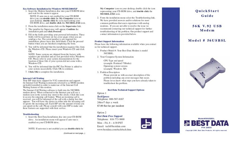
Product Support Information
Please have the following information available when you
contact us for technical support.
1. Product Model # 56SX-92 rev2
2. Your Computer System Information
CPU Type and speed (example: Pentium3 700mhz)
Operating System version (example: Windows XP).
3. Problem Description
Please provide us with an exact description of the problem
including any error messages that occur. Please let us know
what steps you have already taken to troubleshoot the
problem.
Best Data Technical Support Options
Hours: Mon–Fri, 8–4:30 Pacific Time
Phone: 818-773-9600
(Long distance charges may apply)
Email: Visit the online support request form at:
http://www.bestdata.com/contact.htm
Web: www.bestdata.com
Table of contents
Other Best Data Modem manuals

