10
1. Quitelacubiertaylostornillos.
2. Coloqueunconectadordecablesapropiado,
aprobadoporU.L.,enelorificioqueseencuentra
enlaparteposteriordelacajadeconexiones.
3. Quitelosclavossolamentedelastejasquese
encuentran en las partes SUPERIOR y
LATERALESdeláreadecorte.Concuidado
levante las tejas para permitir que la hoja
cubrejuntasposteriordelacubiertadelventilador
quepadebajodeellas.
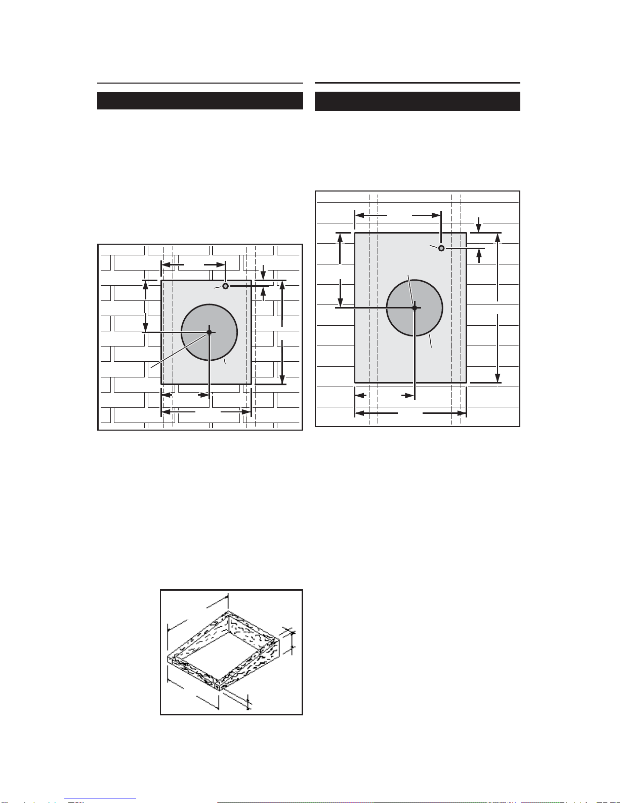
4. Centreelanillodelventiladorenelorificiode11”
(27,9cm),asegurándosedequeelorificiodel
cableadoeléctrico,de1¼”(3,2cm)dediámetro,
quedealineadoconelorificiodelascajade
conexiones.
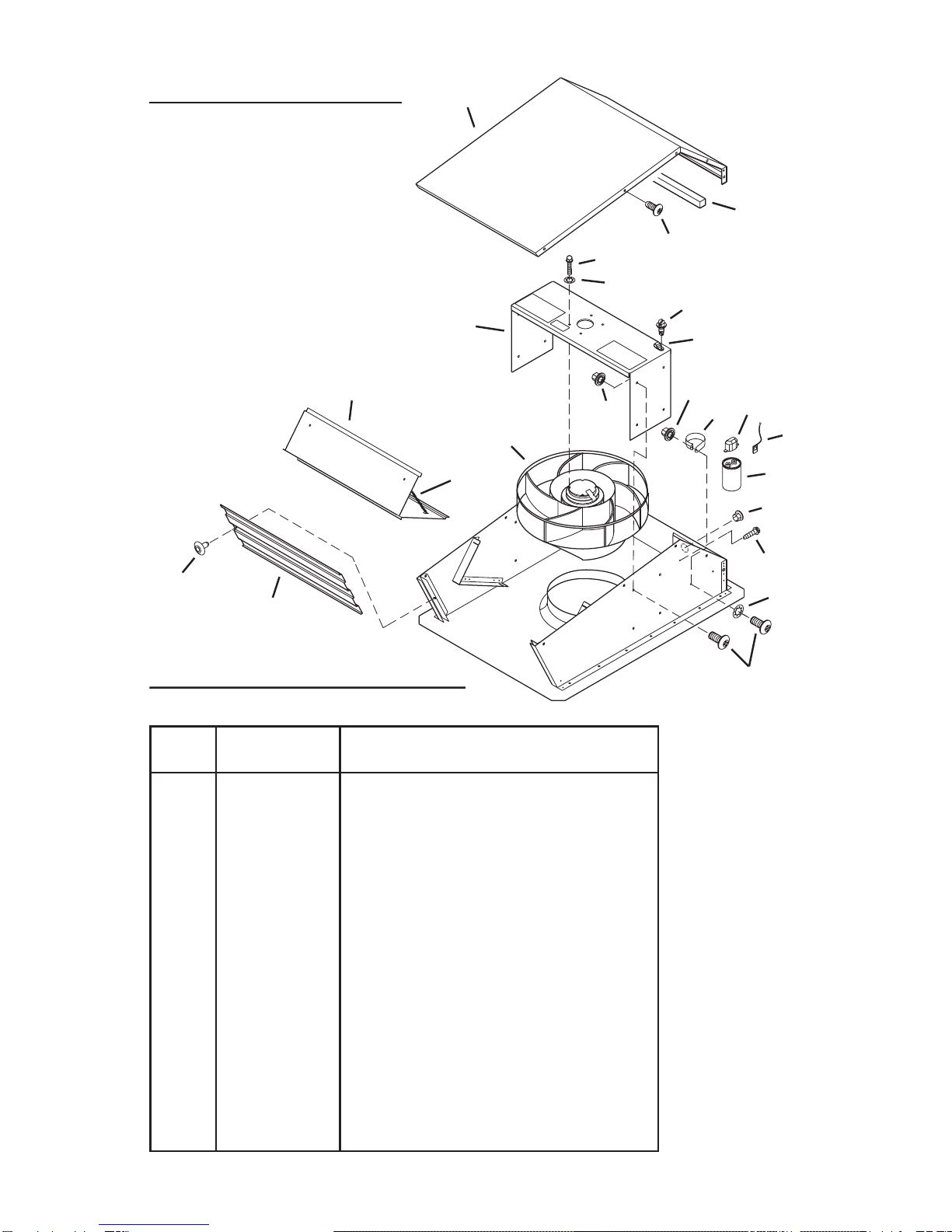
5. Monte el ventilador en el techo con los seis (6)
tornillosquese proporcionan.Serecomiendaque
secoloquenlostornillosenel interiordelacubierta
delventilador.Si esnecesariohagaorificiospiloto.
6. Utilizando un cemento para techo de buena
calidad, selle todas las tejas alrededor de la
cubierta y de la hoja cubrejuntas, así como
alrededordelacabezadelostornillosdemontaje.
7. Paseloscableseléctricosatravésdelorificiodel
lacajadeconexionesysegúrelosdeacuerdocon
loscódigoslocales.
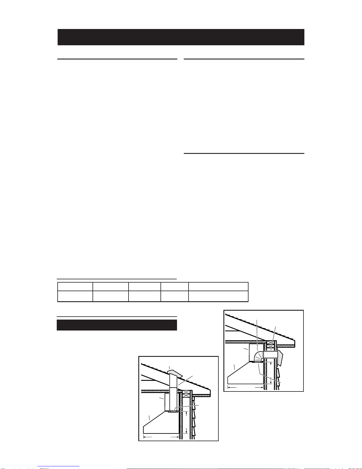
INSTALE DEL
VENTILADOR
INSTALACIONES DE TECHO
INSTALE DEL
VENTILADOR
INSTALACIONES DE PARED
1. Coloqueun rebordegrandedematerialde
calafateoenelladoposteriordelacubierta,alo
largodetodoslosbordesexternos.
2. Centreelanillodelventiladorenelorificiode11”
(27,9cm),asegurándosedequeelorificiodel
cableadoeléctrico,de1¼”(3,2cm)dediámentro,
quedealineado conelorificiode lacajade
conexiones.
3. Monteelventiladorenlaparedconlosseis(6)
tornillosqueseproporcionan.Serecomiendaque
secoloquenlostornillosenelinteriordelas
cubiertadelventilador.Siesnecesariohaga
orificiospiloto.
4. Utilizandomaterialdecalafateodebuenacalidad,
sellealrededordelacabezadelostornillosde
montaje.
5. Paseloscableseléctricosatravésdelorificiode
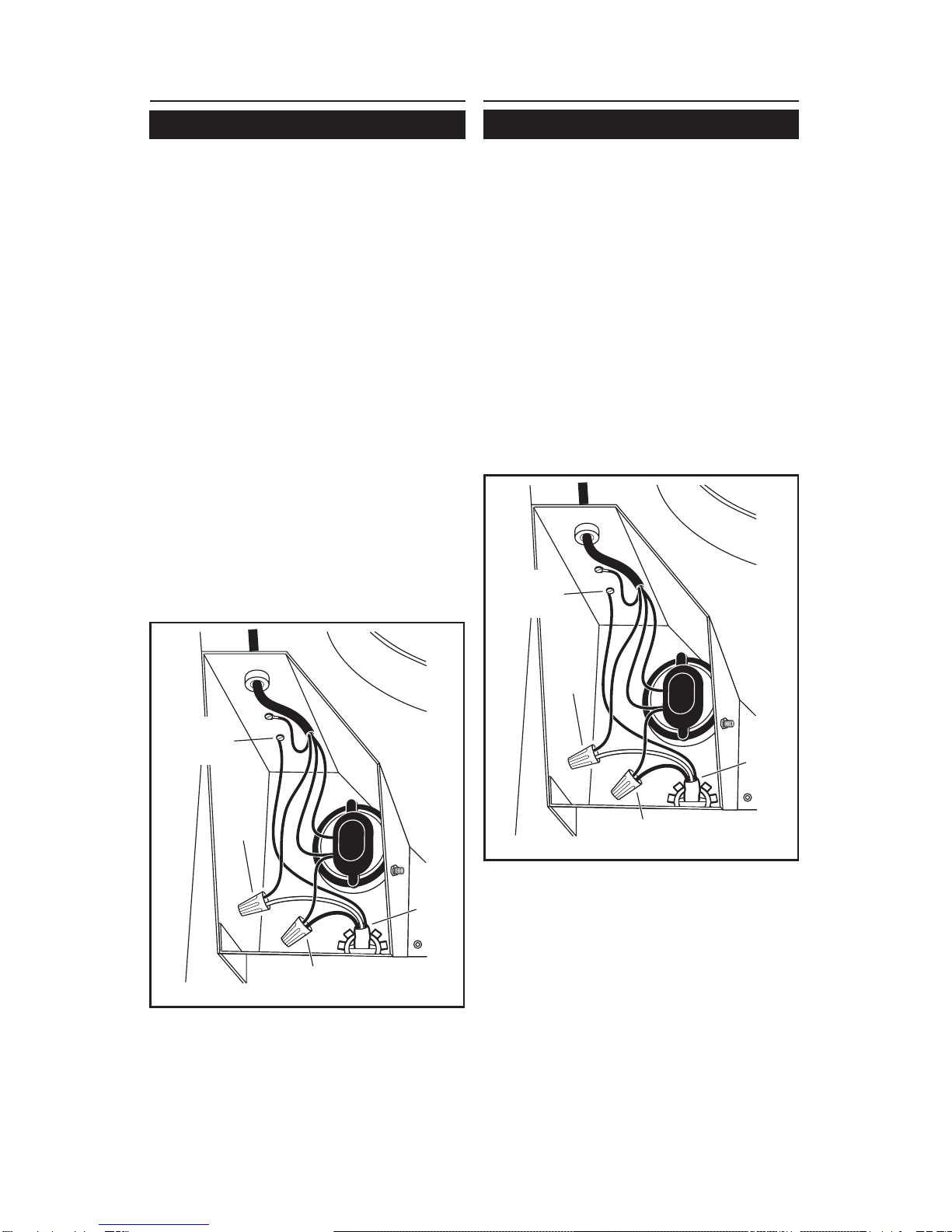
8. Hagalasconexioneseléctricasutilizandoel
conectadoradecuadoparaeltipodecablesque
estáusando.Conecteelnegroconelnegro,el
blancoconelazulyelverdeoelalambredesnudo
altornillodeconexiónatierra.
9. Reemplacelascubiertasylostornillos.Nopermita
queloscablesquedenatrapadosdebajodela
cubierta.
10.Asegúresedequeelreguladordetiroabray
cierrelibremente.
NEGRO A
NEGRO
LÍNEA DE
ENTRADA
120 VCA
BLANCO
A
AZUL
TIERRA AL
TORNILLO DE
CONEXIÓN
A TIERRA
lacajadeconexionesyasegúrelosdeacuerdo
conloscódigoslocales.
6. Hagalasconexioneseléctricasutilizandoel
conectadoradecuadoparaeltipodecablesque
estáusando.Conecteelnegroconelnegro,el
blancoconelazulyelverdeoelalambredesnudo
altornillodeconexiónatierra.
7. Reemplacelascubiertasylostornillos.Nopermita
queloscablesquedenatrapadosdebajodela
cubierta.
8. Asegúresedequeelreguladordetiroabraycierre
libremente.
9. Lasaletassuperiorylateralesdelaplacaposte-
riorsepuedencubrircontirasderesguardo.No
bloqueelaparteinferiordelaaberturadelenrejado
NEGRO A
NEGRO
LÍNEA DE
ENTRADA
120 VCA
BLANCO
A
AZUL
TIERRA AL
TORNILLO DE
CONEXIÓN
A TIERRA