BESTEAM Bestis 1000 Operating instructions

Bestis 1000-10000
User – and Maintenance Manual
Version 1.5

2
EU DECLERATION OF CONFORMITY
WE HEREBY ASSURE THAT THE MACHINE DESCRIBED
BELOW IS MANUFACTURED IN ACCORDANCE WITH EU-
MACHINERY DIRECTIVE 2006/42/EY.
THIS DECLERATION IS NOT VALID, IF MODIFICATIONS
OR REFORMATIONS ARE MADE TO THE MACHINE THAT
ARE CARRIED OUT BY OTHER THAN THE
MANUFACTURER OF THIS MACHINE OR A
REPRESENTATIVE OF THE MANUFACTURER.
BESTEAM OY
Nyrhintie 7
FIN-28760 PORI
Tel. (02) 631 9102
Fax. (02) 631 9101
Machine Description:
Bestis Welding Positioner
Model Bestis Welding Positioner
The Year of Manufacture 2014
Applied Directives EU Machinery Directive 2006/42/EY
(government decree 400/2008)
Harmonized SFS-EN 349, SFS-EN 418, SFS-EN
982,
EN norms SFS-EN 1037, SFS-EN 1050, SFS-EN
1088, SFS-EN 60204-1, SFS-EN
12100-1, SFS-EN 12100-2
In Pori, Finland 22.8.2014
Ilpo Salminen
Managing Director

3
CONTENTS
1 GENERAL....................................................................................................................... 5
2 SAFETY INSTRUCTIONS............................................................................................. 6
3 INSTALLMENT AND DEPLOYMENT........................................................................ 7
3.2 Deployment............................................................................................................... 7
4 USER GUIDE................................................................................................................ 11
4.1 Mounting the workpiece ......................................................................................... 11
4.2 Controlling devices................................................................................................. 11
4.2.1 Main central ..................................................................................................... 11
4.2.2 Remote control................................................................................................. 12
4.2.3 Foot switch....................................................................................................... 13
4.3 Using the load chart and load calculation............................................................... 14
5. ERROR NOTIFICATIONS......................................................................................... 15
5.1. The machine`s start button`s light is blinking rapidly........................................... 15
5.2. The machine`s start button`s light is blinking slowly............................................ 15
5.3. The machine`s start button`s light is blinking irregularly...................................... 15
5.4. The machine`s start button`s light is not on........................................................... 15
6 MAINTENANCE.......................................................................................................... 16
6.1 Maintenance-, check up- and cleaning tasks........................................................... 16
6.2 Maintenance of the electrical device....................................................................... 16
6.3. Maintenance of the hydraulics............................................................................... 17
6.4. Maintenance of the mechanics............................................................................... 17

4
READ FOLLOWING NOTIFICATIONS WITH CARE
BEFORE YOU USE THE WELDING POSITIONER!!
BE CAUTIOUS AND COMPLY WITH GENERAL INSTRUCTIONS GIVEN ON
LIFTING WORKING!!
THE WORKPIECE MUST BE ELECTRICALLY GROUNDED. ALLWAYS USE
THE MACHINE`S OWN ELECTRICAL GROUND CONNECTION AND
FURTHER GROUND-CONNECT DIRECTLY TO THE WORKPIECE, IF
WELDING CURRENT EXCEEDS 500 AMPERES OR THE PIECE IS LARGE.
USE GROUND
CAPLE 70-95 (ABI-
CM 70-95 OR
EQUIVALENT) TO
THE MACHINE`S
OWN GROUND
CONNECTION
CHECK THE SUFFICIENT GROUND CONNECTION OF THE WORKPIECE
BEFORE BEGINNING TO WELD. THE MANUFACTURER IS NOT
RESPONSIBLE FROM CONSEQUENCES RESULTING FROM AN ABSENCE
OF GROUND CONNECTION NOR INSUFFICIENT OR INCORRECT GROUND
CONNECTION.
THE WELDED WORKPIECE MUST NOT TRANSFER HEAT TO THE TABLE
PLATE. THIS IS TO PREVENT DAMAGES FROM OCCURRING TO THE
MACHINE BEARING DUE TO THE THERMAL EXPANSION.
WELDING DIRECTLY TO THE TABLEP LATE IS STRICTLY PROHIBITED!
THE WELDING POSITIONER MUST BE CONNECTED TO A PLUG THAT
CONTAINS RESIDUAL-CURRENT DEVICE!
COMPLY WITH USER MANUAL AND LOAD CHART WITHIN THE MACHINE.
CAREFULLY GET TO KNOW THE LOAD CALCULATION PRACTICES.

5
1 GENERAL
Bestis- welding positioners have been designed for effective handling of different
kinds of workpieces and materials. The welding positioner lifts, tilts and rotates
workpieces to a position, where for example welding, assembling and surface
finishing are carried out in a best manner. If the machine is used in a different
purpose, please ensure its` applicability to this purpose by contacting the
manufacturer or manufacturer`s representative.
The positioners of Bestis- product family have three-axis setting: height, tilt angle
and rotation. The rotation, height adjustment and tilting are carried out by
operating with light-weight remote control. All the models have been
manufactured in accordance with the work safety regulations of the EU.
1. Machine frame
2. Lifting bar
3. Rotation equipment
4. Table plate
5. Tilting cylinder
6. Lifting cylinder
7. Hydraulic set
8. Main central
Note! Because of the work safety reasons, the manufacturer recommends to use
lifting brackets (4 brackets), that are located in the corners of the machine, when
lifting the machine. If the customer demands to install a bracket to the middle of
the machine, using this bracket is at customer`s own liability and risk.

6
2 SAFETY INSTRUCTIONS
The user of the welding positioner ultimately is in charge of the safety
precautions that concerns the user or other people next to the machine. Only
persons that are familiar with the functions of the machine are allowed to operate
the machine, and the given instructions must be applied. We recommend that the
person operating the machine should possess the occupational safety card.
Operating the machine incorrectly resulting in incorrect functions or incorrect
functioning segment might cause an abnormal situation, in which the user as well
as the equipment may be damaged. All types of working, standing, walking etc.
under the workpiece is strictly forbidden.
1. Everyone operating the machine must be well aware of
•operating the machine and correct electrical grounding
•the location of the EMERGENCY SWITCH-OFF (HÄTÄSEIS)
•functions of the machine
•valid work safety regulations
2. Before starting the machine, it must be attended that
•the work area contains no people, who have not been assigned to
work with the machine
•nobody is looking directly at the electric arc
•the electrical grounding has been carried out in accordance with the
given instructions
3. The workplace must be
•suitable for using the machine
•clean and free of any random objects
4. Personal safety equipment
•always use instructed personal equipment, for example safety
goggles, fireproof clothes and safety gloves
•Be careful in using baggy clothes, belts, bracelets etc. that may get
stuck with the machine or workpiece
5. General
•Check that the ground cable has been sufficiently connected and
especially that there no loose connections
•Only the experts of electrical engineering are allowed to fix and
maintain electrical devices
•The necessary fire protection and prevention equipment must
accessible from a place clearly marked
•Lubrication and maintenance of the machine is prohibited while
operating the machine; comply with the given maintenance
instructions

7
3 INSTALLMENT AND DEPLOYMENT
IMPORTANT!
Read all the machine manuals and safety instructions with care before unpacking
or installing of the machine!
NOTE! Make sure that installment is carried out by a qualified person.
3.1 Handling and storing the machine
The machine has been packed on platform suitable for lifting- and/or trucking
handling. The machine must be lift from the 4 brackets located in the corners.
Unpack the machine and check its` visible condition. You are allowed to operate
and store the machine in humidity controlled facilities with a temperature over
+10 °C.
3.2 Deployment
READ THE FOLLOWING NOTIFICATIONS WITH CARE BEFORE THE
DEPLOYMENT:
BE CAUTIOUS AND COMPLY WITH GENERAL INSTRUCTIONS GIVEN ON
LIFTING WORKING!!
THE WORKPIECE MUST BE ELECTRICALLY GROUNDED. ALLWAYS USE
THE MACHINE`S OWN ELECTRICAL GROUND CONNECTION AND
FURTHER GROUND-CONNECT DIRECTLY TO THE WORKPIECE IF
WELDING CURRENT EXCEEDS 500 AMPERES OR THE PIECE IS LARGE.
USE GROUND
CAPLE 70-95 (ABI-
CM 70-95 OR
EQUIVALENT) TO
THE MACHINE`S
OWN GROUND
CONNECTION

8
CHECK THE SUFFICIENT GROUND CONNECTION OF THE WORKPIECE
BEFORE BEGINNING THE WELDING. THE MANUFACTURER IS NOT
RESPONSIBLE FROM CONSEQUENCES RESULTING FROM AN ABSENCE
OF GROUND CONNECTION NOR INSUFFICIENT OR INCORRECT GROUND
CONNECTION.
THE WELDED WORKPIECE MUST NOT TRANSFER HEAT TO THE TABLE
PLATE. THIS IS TO PREVENT DAMAGES FROM OCCURRING TO THE
MACHINE BEARING DUE TO THE THERMAL EXPANSION.
WELDING DIRECTLY TO THE TABLEP LATE IS STRICTLY PROHIBITED!
THE WELDING POSITIONER MUST BE CONNECTED TO A PLUG THAT
CONTAINS RESIDUAL-CURRENT DEVICE!
COMPLY WITH USER MANUAL AND LOAD CHART WITHIN THE MACHINE.
CAREFULLY GET TO KNOW THE LOAD CALCULATION PRACTICES.
1. Place the welding positioner on an even and sustainable ground that is
constructed from unbreakable concrete, whose material strength is 30 N / mm²
minimum.
2. Make sure that there is a sufficient working space around the machine. Also
notify the shapes and dimensions of the workpieces; the handling are of the
workpiece must be free from objects.
3. Get to know the technical data and performance regarding the machine, and
comply with them. Check the weight of the workpiece and its` centre of mass in
relation to the machine`s rotation and tilting axis (see the calculation instructions
and load chart).
4. Make sure that there is a free access to the work spot.
5. Connect the remote control cable to the connector in main central. Before
connecting, check that the main switch is in 0-position.
6. Check that the EMERGECY SWITCH-OFF –button in the remote control is
pressed down.
7. Connect the machine to an electrical grid.
•240/400 V 3-phase 16 A
8. Turn the power on from the main switch of the machine.

9
9. Lift or turn the remote control`s EMERGENCY SWITCH-OFF button up and
push the green start button, after which the green light should be seen in the
button.
10. Test the functions of the machine with the remote control before mounting the
workpiece.
•rotation
•tilt
•lift
11. For welding, connect the ground cable to the ground socket located in the
machine frame. The machine has one ground socket. If you weld with higher
welding current that 500 amperes, further ground-connect directly to the
workpiece.
12. After you have checked the functions of the machine, you may mount the
workpiece to the T-slot in the table plate. The workpiece should be mounted on
table plate in a way that the central mass of the workpiece is closest as possible
to the center of the table plate.
13. MAKE SURE THAT THE WORKPIECE IS WELL-MOUNTED IN THE TABLE
PLATE.
14. Make sure that there is sufficient free space to handle the workpiece. Do
consider the trajectories of the workpiece in different positions of the table plate..
15. You may begin working with the machine, but please continuously observe
the functions of the machine and the mounting of the workpiece.
17. After you have finished working with the workpiece, switch the machine off.

10
18. Make sure that the workpiece will not drop from the table plate, when
demounting the workpiece. Demount the fixtures and lift the workpiece from the
table plate with care, after making sure that the workpiece is no more mounted in
the table plate.
19. Clean the table plate after you have finished working with it.

11
4 USER GUIDE
4.1 Mounting the workpiece
•Mount the workpiece to the T-slots in the table plate using proper
mounting methods; for example using right-sized T-slot nuts.
•Make sure that the mounting is firm throughout the working process.
Secure the mounting regularly!
4.2 Controlling devices
4.2.1 Main central
1. Main switch
2. Start button
3. Selection switch for the foot switch functions
4. Foot switch socket
5. Remote control socket
6. Power socket

12
4.2.2 Remote control
All the machines come with voltage protected 24 V remote control. The machine
functions are set via remote control.
1. Lifting the table plate
2. Lower the table plate
3. Tilting the table plate forward
4. Tilting the table plate backward
5. Rotating the table plate clockwise
6. Rotating the table plate anticlockwise
Continuous clockwise rotation: Press button (5.) and hold it. Next press button
(6.) and release button (6.), after which you can release button (5.). After this the
table plate continuously rotates clockwise, during which the rotation speed can
be adjusted from the knob-controller located in the front end of the remote. The
continuous rotation is stopped by pressing buttons (5.), (6.) or . The continuos
anticlockwise rotation can be employed by following the procedure above in
reverse order.
AFTER AN EMERGENCY SWITCH-OFF SITUATION, IT MUST BE FIRST
ESTABLISHED THAT THE IS DANGER NO LONGER EFFECTIVE BEFORE
TURNING THE MACHINE ON!
DO NOT STEER THE WORKPIECE TO THE FLOOR.
WHEN ROTATING THE WORKPIECE, START WITH AS LOW SPEED AS
POSSIBLE ENSURING THAT THE BALANCE POSITION OF THE MACHINE
DOES NOT SHIFT. IF NEEDED, RAISE THE ROTATION SPEED; STILL
PAYING CLOSE ATTENTION TO THE BALANCE POSITION.
NOTIFY THE POSSIBLE DANGER AREAS CAUSED BY THE MACHINE AND
THE WORKPIECE. BE CAREFUL WITH THE MOVING PARTS OF THE
MACHINE AND ALWAYS FOLLOW THE MOVEMENT OF THE MACHINE
THROUGHOUT THE WORKING PROCESS.

13
ALWAYS USE THE NECESSARY SAFETY EQUIPMENT REQUIRED IN
DIFFERENT TASKS AND CIRCUMSTANCES.
SECURE THE MOUNTING OF THE WORKPIECE REGULARLY.
4.2.3 Foot switch
Connect the foot switch to the foot switch socket in main central (see section
4.2.1. Main central)
Once you have connected the foot switch, it is ready to be operated.
WHILE USING THE FOOT SWITCH, KEEP THE REMOTE CONTROL WITHIN
REACH. BY DOING SO, YOU ARE ABLE TO PRESS THE EMERGENCY
SWTICH-OFF BUTTON QUICKLY IN DANGER SITUATION!
1-position: The foot switch is connected to ON-OFF position. By pressing the
pedal, the rotation goes on and by pressing the pedal again, the rotation goes off.
You can change the rotation direction by using the remote control. After this
pressing the pedal results in rotating the table plate to chosen direction. Should
you change the rotation direction, repeat the above again. You can control the
rotation speed from the knob-controller in the remote control.
0-position: Foot switch is turned off.
2-position: The foot switch is turned to the accelerator position, where the
rotation speed of the table plate can be increased by pressing the pedal more.
Changing the rotation direction is done in similar manner as in the 1-position.
14
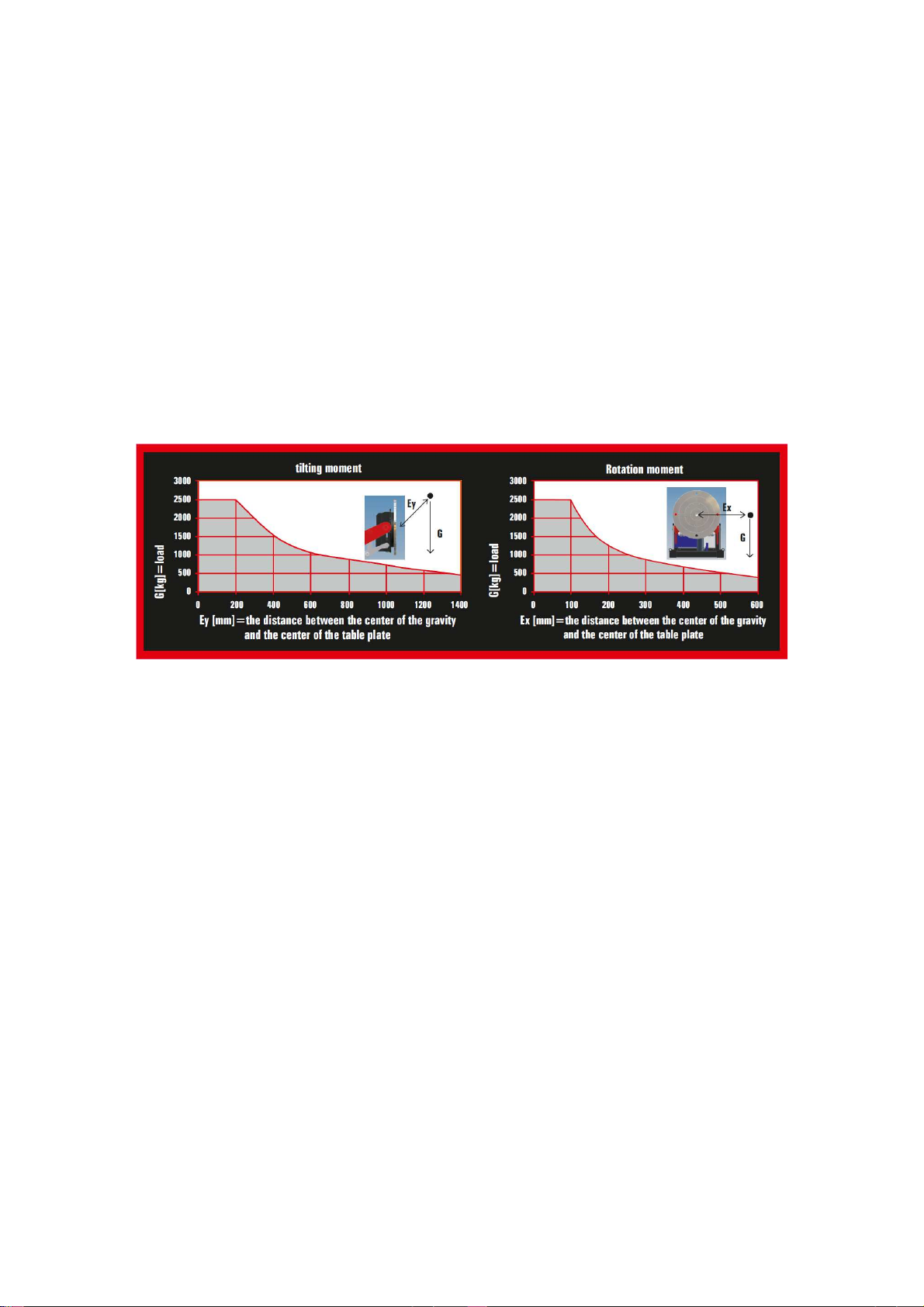
4.3 Using the load chart and load calculation
A load chart has been drawn from each of the welding positioner. The chart
demonstrates that maximum rotation- and tilting moments. This chart can be
found from a sticker that is in the machine frame.
The x-axis describes the distance of the mass center (mm) and the y-axis
describes the load (kg). Max load curve has been drawn to the chart; the load
must be in the permitted area (seen as grey area in the chart).
The load moment must always be calculated from the center of the table plate to
the center mass of the workpiece. The mass centre is the point force of the
workpiece`s mass.
Under no circumstances is the center mass of the
workpiece allowed to be behind the center point
of the table!!
When choosing which positioner to use, the moments needed in handling the
workpiece must be compared to the load chart of the respective welding
positioner.
Y = workpiece mass (kg)
X = distance of the workpiece`s mass center from the center point of the table
plate (mm)

15
5. ERROR NOTIFICATIONS
5.1. The machine`s start button`s light is blinking rapidly
The inspection of the remote control`s buttons is done automatically, when the
control voltage is turned on. If some of the buttons are stuck, the start button`s
light blinks rapidly. The error is checked when the control voltage is turned off for
instance by pressing EMERGENCY SWITCH-OFF button. Try to release the
stuck button or contact the manufacturer or manufacturer`s representative.
5.2. The machine`s start button`s light is blinking slowly
If the machine`s start button`s light starts to blink slowly, some of the following
alarms are valid:
1. a hydraulic motor has become overloaded
- check the thermal shield in the main central (2F1)
2. temperature of the hydraulic oil is too high
- wait for the oil to cool down
3. the rotation motor has become overloaded
- check the error from the frequency changer button in the main central
(STOP/RESET)
If the errors continue contact the manufacturer or manufacturer`s representative.
5.3. The machine`s start button`s light is blinking irregularly
If the machine`s start button`s light starts to blink irregularly, both of the
aforementioned errors have occurred. Check the errors in accordance with
sections 5.1. and 5.2.
5.4. The machine`s start button`s light is not on
The control voltage is missing. Press the start button.

16
6 MAINTENANCE
6.1 Maintenance-, check up- and cleaning tasks
Regularly conducted maintenance and operating the machine correctly will
ensure machine`s long lifetime. Thus, carefully comply with these instructions.
Conduct regular check-ups to the machine so it is ready-to-use when necessary.
Bestis- welding positioners employ and connect electrical-, hydraulic- and
mechanical equipment. The technical failures can be avoided the best by taking
care of the proper maintenance, check-ups and cleaning of this equipment.
Contact the manufacturer of manufacturer`s representative if failure situation
occurs!
Check in daily basis
the machine`s general condition
functioning of the motors
suitability of the workplace
abnormal tremor and sounds
overheating
that the protection- and safety structures are on place and in appropriate
condition.
that the hydraulics is compact
Check regularly
cleanness of the table plate
cleanness of the main central
that the retention bolts are tight
quantity of hydraulic oil
condition of the rotation equipment
condition of the cables
condition of the pressure filters
6.2 Maintenance of the electrical device
The manufacturer has set the machine`s parameters on advance. These
parameters must not be changed.
Check the condition of the remote control, cables and sheating. Cables and
sheating must be intact. Broken cables and sheating must immediately be
changed!
In case of an electrical failure contact the manufacturer or the manufacturer`s
representative!

17
6.3. Maintenance of the hydraulics
The functions of the hydraulic set have been set on advance by the
manufacturer. Only hydraulic oil can be increased when needed. Use the normal
46 hydraulic oil.
Cylinder`s shaft must be kept clean and spherical plain bearings kept
lubricated. The bearings should be lubricated every three months depending
from the usage of the machine. If the usage of the machine heavy or the working
cycles are long, we recommend the lubrication to be done even more often.
When operating the machine, it should be checked that there are no leaks in
the hydraulics. If there are leaks in the joints, check that the all the joints are
tight. Otherwise contact the manufacturer or the manufacturer`s representative!
If the light of the indicator above the pressure filter is red, that means that the
pressure filter is full and it must be replaced. A new filter can be ordered from the
manufacturer or from the manufacturer`s representative. Regardless from the red
light, we recommend to change the filter after one year.
6.4. Maintenance of the mechanics
Regularly clean the T-slot in the table plate. Also check that the bolts in the
table plate and in the external gear are tight. If you`ll observe the bolts loosen,
these bolts should be replaced. Before replacing the bolts please contact the
manufacturer or the manufacturer`s representative!
The electrical grounding is carried out by copper ground electrodes that abrade
table plate. Check that the electrodes are attached to the plate. Remove the
protection cover and confirm the movement of the electrodes by pulling them
upwards. If the electrodes are unable to touch the plate, they have been grinded
too much. In this case the electrodes must be replaced.
The bearing of the external gear must be greased in every 800 working hours.
Remove the protection cover. The lubrication nipple can found by removing the
black plastic plug from the bottom of the rotation motor box.
The tilting mechanism and the bearing of the cylinder must be greased in every
800 working hours or when necessary. Both include lubrication nipples. Do not
put too much grease to the spherical plain bearings, in order to prevent the seals
from displacing.
bes_man_Bestis_1000-10000_eng_2015-04
AXSON TEKNIK AB •S. Långebergsgatan 18 •421 32 Västra Frölunda •
Tel 031-748 52 80
www.axson.se
Axson Teknik är certierade
enl. ISO 9001:2008
This manual suits for next models
1
Table of contents
Popular Valve Positioner manuals by other brands


Val Controls
Val Controls IHP24-A user manual

EBRO ARMATUREN
EBRO ARMATUREN EP 501 B quick start

Dresser
Dresser Masoneilan SVI II AP-2 quick start guide

GE
GE SVi 1000 Masonelian quick start guide

Spirax Sarco
Spirax Sarco CVS10M Installation and maintenance instructions

GEM
GEM eSyStep Q50 operating instructions

GF
GF EA25-250 instruction manual

STI
STI IMI FasTrak Compact FTC-I instructions

cascade corporation
cascade corporation 55K installation instructions

Baker Hughes
Baker Hughes Masoneilan 4700P instruction manual

ABB
ABB TZIDC operating instructions

W.E. Anderson
W.E. Anderson PRECISOR II 165EL Series Installation and operating instructions