www.gemu-group.com 5 / 53 GEMÜ Q50 eSyStep
Positioner (Code S0, S5, S6)
1.6 Safety information on the product
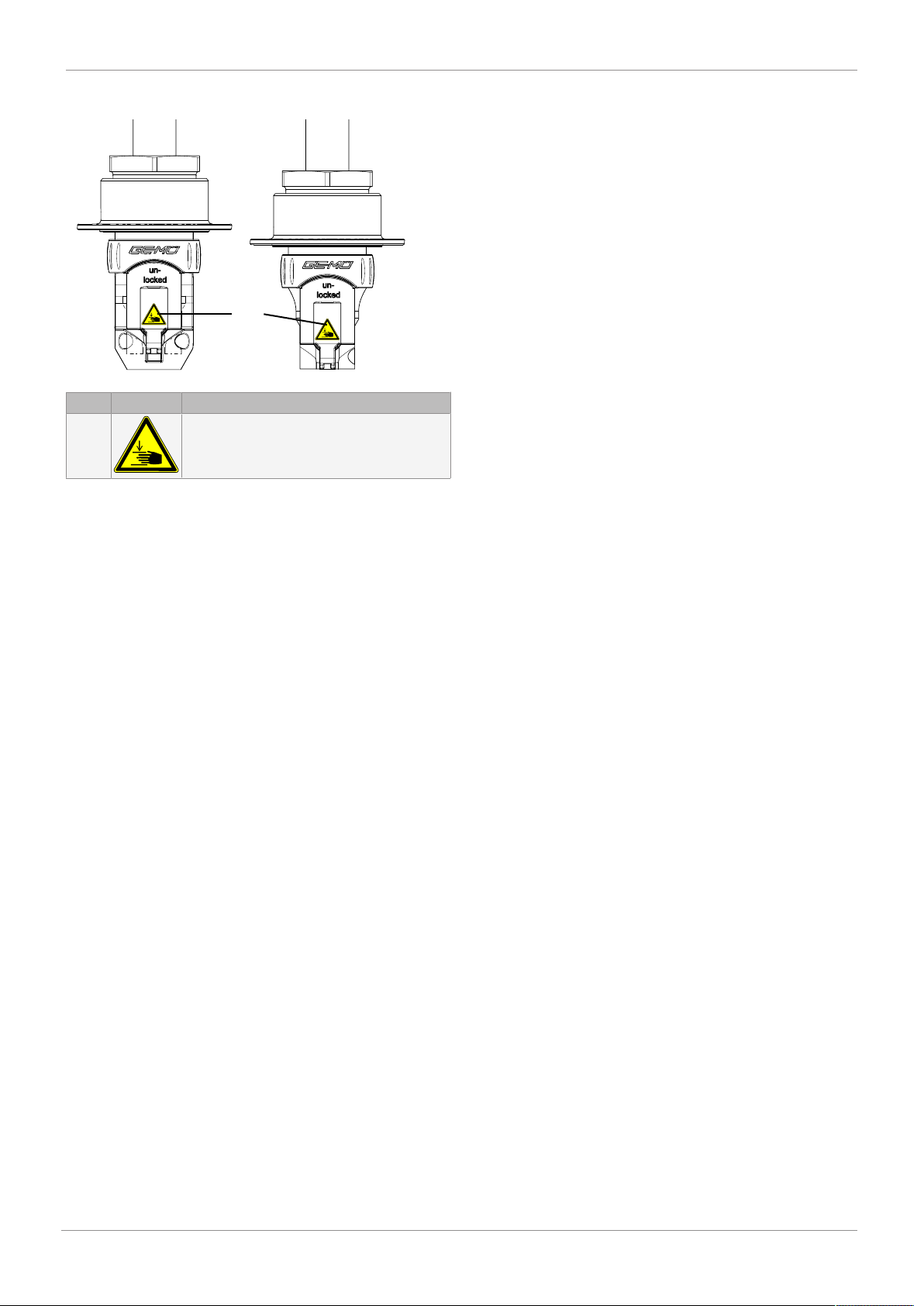
Item Symbol Meaning
1 Risk of crushing!
•Do not reach into the tube crushing
area.
The adhesive label on the product is printed in German, Eng-
lish and French as supplied. If the product is used in a coun-
try where a different language is spoken, a label in the cor-
responding language must be attached.
Missing or illegible adhesive labels on the product must be
attached or replaced.
If the adhesive label is required in other, not enclosed, lan-
guages, it must be produced and attached by the customer at
their own responsibility.
2 Safety information
The safety information in this document refers only to an in-
dividual product. Potentially dangerous conditions can arise
in combination with other plant components, which need to
be considered on the basis of a risk analysis. The operator is
responsible for the production of the risk analysis and for
compliance with the resulting precautionary measures and
regional safety regulations.
The document contains fundamental safety information that
must be observed during commissioning, operation and
maintenance. Non-compliance with these instructions may
cause:
•Personal hazard due to electrical, mechanical and chemical
effects.
•Hazard to nearby equipment.
•Failure of important functions.
•Hazard to the environment due to the leakage of dangerous
materials.
The safety information does not take into account:
•Unexpected incidents and events, which may occur during
installation, operation and maintenance.
•Local safety regulations which must be adhered to by the
operator and by any additional installation personnel.
Prior to commissioning:
1. Transport and store the product correctly.
2. Do not paint the bolts and plastic parts of the product.
3. Carry out installation and commissioning using trained
personnel.
4. Provide adequate training for installation and operating
personnel.
5. Ensure that the contents of the document have been fully
understood by the responsible personnel.
6. Define the areas of responsibility.
7. Observe the safety data sheets.
8. Observe the safety regulations for the media used.
During operation:
9. Keep this document available at the place of use.
10. Observe the safety information.
11. Operate the product in accordance with this document.
12. Operate the product in accordance with the specifica-
tions.
13. Maintain the product correctly.
14. Do not carry out any maintenance work and repairs not
described in this document without consulting the manu-
facturer first.
In cases of uncertainty:
15. Consult the nearest GEMÜ sales office.
2 Safety information