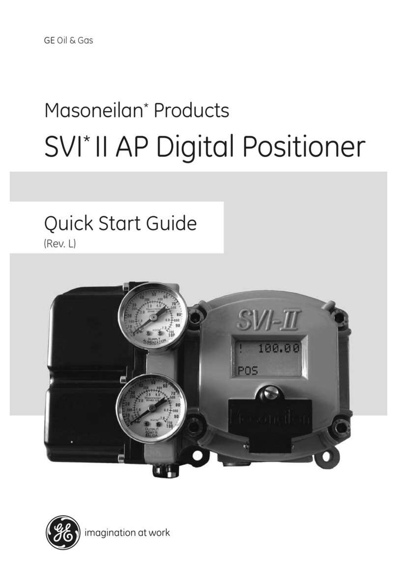
GE SVi 1000 Masonelian User manual

GE Oil & Gas
Masoneilan*
SVi*1000 Positioner
Quick Start Guide (Rev F)
GE Data Classification: Public
QSTBD
10/10 - Rev A

© 2016 General Electric Company. All rights reserved.
2 | =GE Oil & Gas
About this Guide
This Quick Start Guide applies to the SVi1000 instrument and supported software:
with firmware version 2.2.1 (for use with HART®5) or 3.1.1 (for use with HART®7).
with ValVue 3 version 3.20.0 or greater
with a HART®Communicator with DD published for SVi1000
The information in this manual is subject to change without prior notice.
The information contained in this manual, in whole or part, shall not be transcribed or copied without the
General Electric Company’s written permission.
In no case does this manual guarantee the merchantability of the positioner or the software or its adapt-
ability to a specific client needs.
Please report any errors or questions about the information in this manual to your local supplier or visit
www.geoilandgas.com/valves.
DISCLAIMER
THESE INSTRUCTIONS PROVIDE THE CUSTOMER/OPERATOR WITH IMPORTANT PROJECT-SPECIFIC REF-
ERENCE INFORMATION IN ADDITION TO THE CUSTOMER/OPERATOR’S NORMAL OPERATION AND MAIN-
TENANCE PROCEDURES. SINCE OPERATION AND MAINTENANCE PHILOSOPHIES VARY, GE (GENERAL
ELECTRIC COMPANY AND ITS SUBSIDIARIES AND AFFILIATES) DOES NOT ATTEMPT TO DICTATE SPECIFIC
PROCEDURES, BUT TO PROVIDE BASIC LIMITATIONS AND REQUIREMENTS CREATED BY THE TYPE OF
EQUIPMENT PROVIDED.
THESE INSTRUCTIONS ASSUME THAT OPERATORS ALREADY HAVE A GENERAL UNDERSTANDING OF THE
REQUIREMENTS FOR SAFE OPERATION OF MECHANICAL AND ELECTRICAL EQUIPMENT IN POTENTIALLY
HAZARDOUS ENVIRONMENTS. THEREFORE, THESE INSTRUCTIONS SHOULD BE INTERPRETED AND
APPLIED IN CONJUNCTION WITH THE SAFETY RULES AND REGULATIONS APPLICABLE AT THE SITE AND
THE PARTICULAR REQUIREMENTS FOR OPERATION OF OTHER EQUIPMENT AT THE SITE.
THESE INSTRUCTIONS DO NOT PURPORT TO COVER ALL DETAILS OR VARIATIONS IN EQUIPMENT NOR TO
PROVIDE FOR EVERY POSSIBLE CONTINGENCY TO BE MET IN CONNECTION WITH INSTALLATION, OPERA-
TION OR MAINTENANCE. SHOULD FURTHER INFORMATION BE DESIRED OR SHOULD PARTICULAR PROB-
LEMS ARISE WHICH ARE NOT COVERED SUFFICIENTLY FOR THE CUSTOMER/OPERATOR'S PURPOSES THE
MATTER SHOULD BE REFERRED TO GE.
THE RIGHTS, OBLIGATIONS AND LIABILITIES OF GE AND THE CUSTOMER/OPERATOR ARE STRICTLY LIM-
ITED TO THOSE EXPRESSLY PROVIDED IN THE CONTRACT RELATING TO THE SUPPLY OF THE EQUIPMENT.
NO ADDITIONAL REPRESENTATIONS OR WARRANTIES BY GE REGARDING THE EQUIPMENT OR ITS USE
ARE GIVEN OR IMPLIED BY THE ISSUE OF THESE INSTRUCTIONS.
THESE INSTRUCTIONS ARE FURNISHED TO THE CUSTOMER/OPERATOR SOLELY TO ASSIST IN THE INSTAL-
LATION, TESTING, OPERATION, AND/OR MAINTENANCE OF THE EQUIPMENT DESCRIBED. THIS DOCU-
MENT SHALL NOT BE REPRODUCED IN WHOLE OR IN PART TO ANY THIRD PARTY WITHOUT THE WRITTEN
APPROVAL OF GE.
Copyright
All software is the intellectual property of GE Oil & Gas. The complete design and manufacture of the
SVi1000 Smart Valve Interface is the intellectual property of GE Oil & Gas.
Copyright 2016 by General Electric Company. All rights reserved.
PN 720008664-779-0000 REV F

Document Changes
Version/Date Changes
B/1-2012 Updated ES-761 to Rev. B.
C/4-2012 Updated ES-761 to Rev. D.
D/5-2013 Updated Figure 6 Rotary Kit Components.
E/9-2013 Updated load limits switch drawing and added a reference
to that section in installation. Added polarity caution to the
Load Limits section. Inserted ES-761 Rev. E.
F/03-2016 Updated load limits section.
Updated wiring and general descriptions to include retrans-
mit wiring and features.
Inserted ES-761 Rev. F.
Updated all references to ValVue to reflect on ValVue version
3, along with licensing changes.
Masoneilan SVi1000 Positioner Quick Start Guide =| 3
© 2016 General Electric Company. All rights reserved.

This page intentionally left blank.

© 2016 General Electric Company. All rights reserved.Masoneilan SVi1000 Positioner Quick Start Guide | 5
Contents
1. Safety Information ................................................................................7
Documentation Symbols.......................................................................................................................... 7
SVi1000 Product Safety............................................................................................................................. 8
2. Introduction ...........................................................................................11
Introduction.................................................................................................................................................... 11
Functionality................................................................................................................................................... 12
Modes................................................................................................................................................................ 15
LED Light Functions .................................................................................................................................... 17
Major Components...................................................................................................................................... 19
3. Mounting and Wiring ............................................................................21
Introduction.................................................................................................................................................... 21
Step 1: Mounting the SVi1000................................................................................................................ 23
Necessary Precautions ........................................................................................................................23
Mounting the SVi1000 on Rotary Valves .....................................................................................24
Mounting the SVi1000 on Reciprocating Valves ......................................................................29
Integrated Magnet Assembly ...........................................................................................................32
Step 2: Connecting the Tubing and Air Supply............................................................................... 33
Step 3: Wiring the SVi1000 ...................................................................................................................... 34
Wiring Guidelines ....................................................................................................................................35
Wiring an SVi1000 Unit ........................................................................................................................36
4. Check Out and Configuration .............................................................41
Overview .......................................................................................................................................................... 41
Step 1: Inspect the Actuator, Linkages, or Rotary Adapter ...................................................... 42
Step 2: Verify Mounting and Linkage Adjustment ........................................................................ 42
Step 3: Checking the Magnet.................................................................................................................. 42
Perform a Visual Inspection ..............................................................................................................42
Use ValVue to Check Magnet Position .........................................................................................43
Step 4: Checking the Air Supply............................................................................................................. 43
Step 5: Verify Wiring Connections........................................................................................................ 44
Step 6: Configuration.................................................................................................................................. 44
Auto Find Stops .......................................................................................................................................45
Open Stops Adjustments ....................................................................................................................45
Tuning ..........................................................................................................................................................46
Auto Tune ...................................................................................................................................................49
5. ValVue Software and the SVi1000 ......................................................51
ValVue Overview .......................................................................................................................................... 51

© 2016 General Electric Company. All rights reserved.
6 | GE Oil & Gas
ValVue and SVi1000 DTM Trial Version .............................................................................................51
ValVue and SVi1000 DTM Software Installation .......................................................................52
HART® Handheld Communicator........................................................................................................ 58
Appendix A. SVi1000 Theory ....................................................................59
Introduction .................................................................................................................................................... 59
SVi1000 Setups ........................................................................................................................................59
Grounding Practices ..............................................................................................................................60
Compliance Voltage in Single Drop Current Mode .................................................................60
Appendix B. Optional Switch Load Limits ..............................................61
General Configuration Notes.................................................................................................................. 61
Optional Retransmit Output.................................................................................................................... 63
Appendix C. Specifications, Spare Parts and References ...................65
Introduction ...............................................................................................................................................63
Physical and Operational Specifications........................................................................................... 65
Spare Parts...................................................................................................................................................... 71
Hazardous Location Installation and Declaration of Conformity.......................................... 72

Masoneilan SVi1000 Positioner Quick Start Guide =| 7
© 2016 General Electric Company. All rights reserved.
This section provides safety information and defines the documentation symbols.
Documentation Symbols
SVi1000 instructions contain warnings, cautions and notes, where necessary, to alert you to
safety related or other important information. Read the instructions carefully before installing
and maintaining your instrument. Total compliance with all WARNING, and CAUTION notices is
required for safe operation.
WARNING Indicates a potentially hazardous situation, which if
not avoided could result in serious injury or death.
CAUTION Indicates a potentially hazardous situation, which if
not avoided could result in instrument or property
damage, or data loss.
NOTE Indicates important facts and conditions.
1. Safety Information

© 2016 General Electric Company. All rights reserved.
8 | =GE Oil & Gas
SVi1000 Product Safety
For SVi1000 positioners intended for use with industrial compressed air:
Ensure that an adequate pressure relief provision is installed when the application of system
supply pressure could cause peripheral equipment to malfunction. Installation must be in accor-
dance with local and national compressed air and instrumentation codes.
General installation, maintenance or replacement
Products must be installed in compliance with all local and national codes
and standards by qualified personnel using safe site work practices.
Personal Protective Equipment (PPE) must be used per safe site work
practices.
Ensure proper use of fall protection when working at heights, per safe site
work practices. Use appropriate safety equipment and practices to prevent
the dropping of tools or equipment during installation.
Under normal operation, compressed supply gas is vented from the SVi1000
to the surrounding area, and may require additional precautions or
specialized installations.
Intrinsically Safe Installation
Products certified for use in intrinsically safe installations MUST BE:
Installed, put into service, used and maintained in compliance with national
and local regulations and in accordance with the recommendations
contained in the relevant standards concerning those environments.
Used only in situations that comply with the certification conditions shown
in this document and after verification of their compatibility with the zone of
intended use and the permitted maximum ambient temperature.
Installed, put into service and maintained by qualified and competent
professionals who have undergone suitable training for instrumentation
used in such areas.
WARNING Before using these products with fluids/compressed gases other
than air or for non-industrial applications, consult the factory.
This product is not intended for use in life support systems.
WARNING Do not use damaged instruments.

Masoneilan SVi1000 Positioner Quick Start Guide =| 9
© 2016 General Electric Company. All rights reserved.
WARNING Installation in poorly ventilated confined areas, with any potential
of gases other than oxygen being present, can lead to a risk of
personnel asphyxiation.
Use only genuine replacement parts which are provided by the manufacturer, to guarantee that
the products comply with the essential safety requirements of the European Directives.
Changes to specifications, structure, and components used may not lead to the revision of this
manual unless such changes affect the function and performance of the product.

This page intentionally left blank.

Masoneilan SVi1000 Positioner Quick Start Guide =| 11
© 2016 General Electric Company. All rights reserved.
Introduction
The SVi1000 Quick Start Guide is intended to help an experienced field technician efficiently in-
stall and setup an SVi1000. If you experience problems that are not documented in this guide,
refer to the SVi1000 Instruction Manual, call your local representative, go to
www.geoilandgas.com/valves, or contact our helpdesk at (+1) 888-784-5463. Sales offices are
listed on the last page of this document.
This section gives an introduction to the positioner and its components.
2. Introduction

© 2016 General Electric Company. All rights reserved.
12 | =GE Oil & Gas
Functionality
All connections to electronic module in the unit are made through the interface board. The
SVi1000 standard interface board has a terminal block with screw connectors.
Optionally, you can order a unit configured with two digital switches or a 4 - 20 mA position re-
transmit output.
Figure 1 shows the standard interface board.
Auto Find Stops
Button and LED 1 Cancel/ Status Button and LED 4
Upper Stop
Button and LED 2 Ground
Auto Tune
Button and LED 3 Configuration Selection Switch
4- 20 mA Input Signal
Open Stop
Adjustment Screw
15
2 6
3 7
4 8
1
2
3
4
5
6
7
8
Figure 1 Operator Controls - Standard

Masoneilan SVi1000 Positioner Quick Start Guide =| 13
© 2016 General Electric Company. All rights reserved.
Figure 2 shows the optional switch interface board and optional gauges.
Solid State
Solid State Switch
SW #1 (Optional)
(Optional)
Gauges
(Optional)
Switch SW #2
Figure 2 Optional Digital Switches and Gauges
Figure 3 shows the optional position retransmit interface board and optional gauges.
Ground
4-20 mA
Input Signal
4-20 mA
Output Signal
(optional)
Gauges
(Optional)
Figure 3 Optional Position Retransmit

© 2016 General Electric Company. All rights reserved.
14 | =GE Oil & Gas
The local user interface is where you configure the unit and perform system operations. These
operations consists of:
Configuration
Selection
Switch
This switch provides control to the following functions:
Actuator Air Action
Select autotuned or preset tuning parameters
Auto Find
Stops
This function automatically sets the lower and upper stops. See “Auto
Find Stops” on page 45 for this procedure.
Open Stop
Adjustment
Use the Open Stop Adjustment screw to perform an upper stop
adjustment and save it to the device. See “Open Stops Adjustments”
on page 45 for this procedure.
Autotuning The autotune process determines optimum tuning parameters for
the valve being commissioned. This function is only active when the
Configuration Selector Switch is set to AutoTune. See “Auto Tune” on
page 49 for this procedure.

Masoneilan SVi1000 Positioner Quick Start Guide =| 15
© 2016 General Electric Company. All rights reserved.
Modes
The SVi1000 provides the following modes of operation
Normal mode
HART®Override mode (ValVue Manual and Setup Modes)
Failsafe mode
Commission Process (Via Local User Interface)
Find Stops via Local User Interface
Manual upper stops adjustment via Local User Interface
Autotune via Local User Interface
The SVi1000 always starts up in the mode that the unit was last in before power down, except for
failsafe mode when the condition causing fail safe has been corrected.
WARNING Always ensure the SVi1000 has returned to Normal mode after
any configuration activity.
Normal Mode In this mode the valve follows the 4-20 mA input signal.
HART®
Override
mode
In HART®override mode, the local user interface buttons are disabled
until any button is pushed, then local control is reestablished.
This, from the instrument interface, functions as Manual and Setup
mode from the optional laptop-based software and other HART®
interface tools.
In HART®Override Mode the following tasks are supported over
HART®by ValVue or DTM based interface:
Set Characterization (Linear,
Equal%(30,50,Camflex), Quick
Open and Custom
Enable or Disable Bumpless
Transfer
Set Near Closed Value Allow Tune to Override limits
Configure Tight Shutoff Set Lower and Upper Position
Limits
Configure Position Fault
Limits (Position Error Band and
Time 1)
Configure Switch I/O
Run Find Stops Run AutoTune (Provided the
option is set at the local user
interface)

© 2016 General Electric Company. All rights reserved.
16 | =GE Oil & Gas
Failsafe Mode When a fault results in Failsafe mode being activated, the output
pressure of the SVi1000 is set low and the red status LED illuminates
continuously. If the fault is considered self-clearing, then once cor-
rected, the unit returns to Normal mode. If the fault is not self-clear-
ing, then the unit requires a reset after correcting the failsafe
condition.
Commission
Processes
These are temporary states activated when a local user interface
issued command dictates their use. When the positioner is in a Com-
mission Processes a status light indicates this activity (see “LED Light
Functions” on page 17). Examples of Commission Processes are Auto
Find Stops and Auto Tune. Once a task completes the unit returns to
Normal mode.
Perform a Manual Find Stops Set Open Stop Adjustment
Set Valve Position Command valve to full open or
closed

Masoneilan SVi1000 Positioner Quick Start Guide =| 17
© 2016 General Electric Company. All rights reserved.
LED Light Functions
Figure 4 shows the local user interface LEDs and explains their patterns and timings.
LED 1 (Green)
LED 2 (Green)
LED 3 (Green)
LED 4 (Red)
Figure 4 SVi1000 LEDs
In Table 1 dots represent an LED being active and dashes represent the LEDs off. The pattern
shown recurs as long as that condition exists.
LED 1 (Green)
LED 2 (Green)
LED 3 (Green)
LED 4 (Red)
Figure 5 Example LED Pattern
Table 1: LED Light Patterns and Troubleshooting
Indication Pattern
Normal mode
LED 1
LED 2
LED 3
Device Alert
(Fault mode
(self-correcting))
Out of Service
(HART®Override
mode)
LED 1
LED 2
LED 3
LED 4
LED 1
LED 2
LED 3
LED 4

© 2016 General Electric Company. All rights reserved.
18 | =GE Oil & Gas
Failsafe mode
Troubleshooting
Device is not
powered or in
Low Power
mode
All LEDs off. Power is not sufficient.
Process Failure
or or
Pattern depends on which process failed and repeats until Cancel button
is pushed.
Setting out of
range
If a setting is out of range the associated Green LED flashes at twice the
rate as normal until an acceptable range is applied.
Table 1: LED Light Patterns and Troubleshooting (Continued)
Indication Pattern
LED 1
LED 2
LED 3
LED 4

Masoneilan SVi1000 Positioner Quick Start Guide =| 19
© 2016 General Electric Company. All rights reserved.
Major Components
Figure 6 shows the unit’s major components for reference.
Electronics
Module
Pneumatic
I/P
Relay
Terminal
Board
Figure 6 SVi1000 Major Components

This page intentionally left blank.
Table of contents
Other GE Valve Positioner manuals
Popular Valve Positioner manuals by other brands

Aerotech
Aerotech ANT95L Series Hardware manual

PI
PI UPL-120 Short instructions

Dwyer Instruments
Dwyer Instruments Proximity 195 Series Specifications-installation and operating instructions

Siemens
Siemens SIPART PS2 6DR5xx0 series Compact operating instructions

ABB
ABB TZIDC manual

Pepperl+Fuchs
Pepperl+Fuchs PGV...-F200...-R4-V19 Series manual

PI
PI P753 user manual

Will Burt
Will Burt POSITIONIT MM233TX2TXRX2 Operator's manual

Flowserve
Flowserve Logix 3200IQ Replacement instructions

Samson
Samson FOUNDATION 3730-5 Mounting and operating instructions

Samson
Samson 3730-4 Mounting and operating instructions

Samson
Samson 3725 series Mounting and operating instructions