BESTTEN USP-OS02 User manual
Motion Sensor Light Switch
Model Number: USP-OS02
USER MANUAL
Occupancy & Vacancy, Single Pole, Neutral Wire Required
WARNINGS AND CAUTIONS
SPECIFICATIONS
Voltage ................................................................ 120V/277VAC, 60Hz
Load capacity ............................................................ 120V 300W LED
800W/VA@120V fluorescent lamp Rapid Start
1200W/VA@277V fluorescent lamp Rapid Start
HP Rating ................................................................................... 1/6HP
Time Delay Adjustment ...........................................15 secs to 30 mins
Operating Temperature ................................ 32° to 131°F (0° to 55°C)
Operation humidity range...............................95%RH,non-condensing
Coverage range ............................................................... 180 Degrees
COVERAGE AREA
BESTTEN
Power for Today, Ideas for Tomorrow
DESCRIPTION
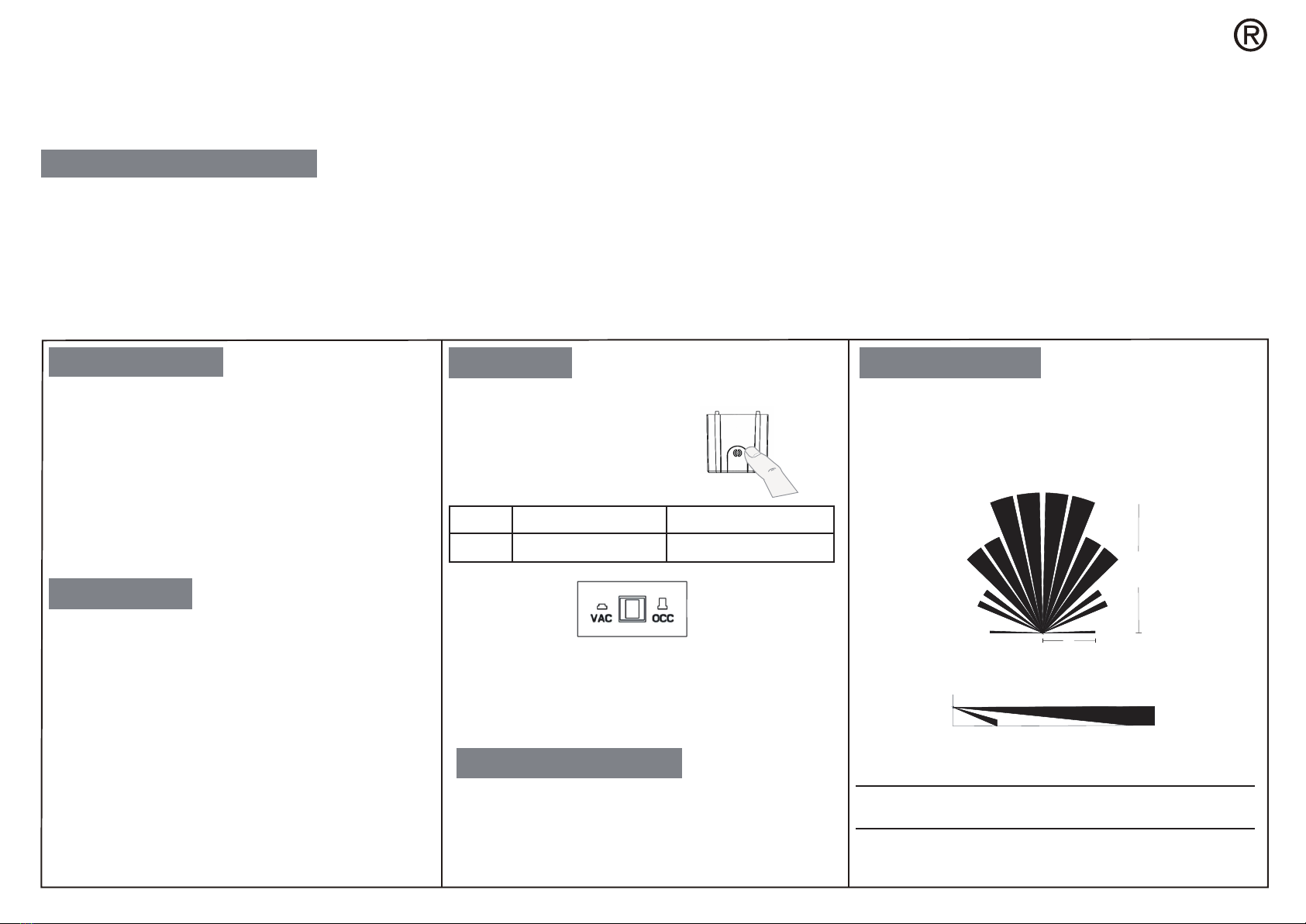
OPERATION
For sensor to operate, the ON/OFF switch
MUST
be manually pushed
one time after installation or a power outage.
VAC When the button is pressed Manual ON, Auto OFF
OCC When the button is released Auto ON, Auto OFF
with Auto set mode*
*Auto Set Mode
If the switch is turned OFF manually, automatic-ON is re-enabled when no
motion is detected for 1 minute. This prevents the switch from turning ON
after it was deliberately turned OFF.
Windows, glass doors, and other transparent barriers
will obstruct the sensor’s view and prevent detection.
Note: The coverage area data is measured under the best temperature condition
(20-25℃), and a higher temperature may not lead to an ideal coverage area.
1. To avoid overheating and possible damage to this device and other equipment, DO NOT
install to control a receptacle.
2. To be installed and/or used in accordance with appropriate electrical codes and regulations.
3. Use this device with copper or copper clad wire only.
4. The neutral wire is required. If no neutral is available, consult an electrician
5. The sensor switch requires an unobstructed view of room occupants to detect motion.
6. Hot objects or moving air currents can affect the performance of the sensing switch.
7. For indoor use only. Operate between 32° to 131°F (0° to 55°C).
8. Clean the sensor with a soft damp cloth only. DO NOT use any chemical cleaners.
9. If you are unsure about any part of these instructions, consult an electrician.
10. Wiring Diagram or equivalent giving the electrical rating and illustratinghow connections
to the supply circuit are to be made.
11. The device is to be used in conjunction with a UL Listed Cover Plate.
12. Intended for use with eletronic ballast, Type ICN-4S54-90C-2LS-G, manufactured by
Philips Lighting Electronics N A.
13. For supply connections use 18AWG or larger wires suitable for at least 75°C
1. The sensor switch turns lights or fans ON and OFF based on
occupancy/vacancy and ambient light level.
2. The sensor uses passive infrared technology to sense human
motion and defines it as occupancy. A green LED indicator on the
control panel blinks upon occupancy and then resets.
3. The sensor turns on automatically when it detects occupancy. Once
the space is vacant and the time delay elapses, it turns off automati-
cally.
4. Occupancy sensor can be converted to vacancy sensor.
5. If adequate ambient light is already present in the area, the sensor
will remain OFF. When the light drops below a set level and the sensor
detects occupancy, the sensor turns on. The light sensor can be
bypassed by setting the light sensitivity dial.
6. Once turned on, the switch remains ON until the space is vacant, or
the ambient light rises above the setpoint and the time delay expires.
The sensor responds to temperature changes so DO NOT mount it
directly above a heat source in a location where hot or cold drafts
will blow directly on it, or where an unintended motion (e.g., hallway
traffic) is within the sensor’s field-of-view.
LOCATION / MOUNTING
COVERAGE PATTERNS: The sensor detects motions in areas up to
720 sq. ft. and up to 30 feet from the sensor. The Fresnel lens on the
sensor is a multiple segment viewing lens with a field of view of 180.
The sensor must have a clear view of the people in the space in order
to detect occupancy. Obstructions, such as furniture blocking the
sensor’s lens may prevent occupancy detection.
Floor
Side View
4.0’
(1.2m)6.0’
(2.0m)
30’
(9.1m)
Top View
12’
(3.7m)
30’
(9.1m)
120V 300W LED, 800W/VA @120V fluorescent lamp Rapid Start, 1200W/VA @277V fluorescent lamp Rapid Start

WARRANTY
BESTTEN warrants to the original customer that this productis free
of defects in materials and workmanship for one year from the
purchase date. Within this period, simply contact BESTTEN CARE
with proof of purchase and reason for claim. We will replace the
product for free.
Any product which is subject to misuse or accidental damage is
excluded from this warranty.
1-800-358-6160 (Mon-Fri 9AM-5PM PST)
For more products from BESTTEN, please visit our website
www.ibestten.com.
STEP 1 Turn OFF Power at Breaker or Fuse
INSTALLATION TROUBLESHOOTING
SENSOR ADJUSTMENT & PROGRAMMING
STEP 2 Remove Wallplate and Switch
• Pull off the pre-cut insulation from the sensor wires.
• Make sure that the ends of the wires from the wall box are
straight (cut and strip if necessary).
STEP 3 Prepare Wires:
STEP 4 Wire the Sensor:
Wire in accordance with the appropriate wiring diagram below.
Before installation, please confirm that there is a Neutral Wire
available in the wall box you intend to install this switch. It can
be identified by 2 or more white wires connected together in
the wall box without being connected to a standard switch.
HOT:
identify the Hot Wire in the wall box which has power from the
breaker pannel.This is usually a black wire. Connect it to the black
wire on this switch.
LOAD:
this is usually the other black wire which delivers power to
the light and does not have power. Connect it to the red load wire
on this switch.
NEUTRAL:
connect the white wire on this switch to the existing
Neutral wire.
GROUND:
connect the green wire on this switch to the existing
Green or bare copper wire in the wall box.
STEP 5
Mount the switch into the electrical box and install the
walllplate.
STEP 6 Restore power and test the switch
NOTE:
For sensor to operate, the ON/OFF switch
MUST
be manually pushed
once after installation or a power outage.
Remove the cover located below the sensor lens by inserting a small
screwdriver into the notch located on the bottom of the cover. Gently
pry the screwdriver upward to unlatch the cover.
Time Delay Dial
The time delay dial is marked “TIME”. The adjustment ranges from 15
secs (or Test) to Max 30 Mins.
Sensor Sensitivity Range Dial
The sensitivity adjustment is marked “SENSE”. Adjust the sensitivity
setting to avoid unwanted detection such as hallway traffic or adjacent
movement. Turning the dial counter clockwise will decrease sensitivity
while turning it clockwise will increase it.
Ambient Light Level Dial
This light level dial is marked “LIGHT”. Light setting is used to adjust the
detected ambient light level. The switch will turn on when the light falls
below the set ambient light level. If ambient light level is desired, please
turn the adjustment knob counter clockwise, and push the button to
make sure the sensor start to work. If the ambient light sensor is not
needed, please set it to the maximum setting (Position 5). This will allow
the sensor to turn on and off regardless of ambient light conditions.
Load will not turn ON
Push the ON/OFF button. The load should turn ON. If not:
• Check the light bulb and/or motor switch on the fan mechanism.
• Turn off power to the circuit then check wire connections.
Load will not turn OFF
• Make sure no motion is occurring in the coverage area until the set
time period.
• Hot air currents and heat radiating devices can cause false
detection. Make sure the sensor is at least 6 feet (2 meters) away
from devices that are a significant heat source (e.g., heater, heater
vent, high wattage light bulb).
• Push the ON/OFF button to the OFF. If load does not turn off, turn
off power to the circuit then check wire connections.
Lights turn ON unwantedly or too frequently.
•Sensor may be mounted too closely to an air conditioning or heating
vent. Move the sensor to another location or close the vent.
•Reduce the sensitivity level.
The sensor is only compatible with a single pole circuit.


