Beyerdynamic CA 4588 User manual

BEDIENUNGSANLEITUNG
OPERATING INSTRUCTIONS
NOTICE D’UTILISATION
CA 4588
Digital / Analog Interface
Digital / Analogue Interface
Interface numérique / analogique


CA 4588 – Inhalt / Contents / Sommaire 3
deutsch
Inhalt
1. Anschluss- und Kontrollelemente. . . . . . . . . . . . . . . . . . . . . . . . . . . . . . . . . . . Seite 4
2. Anschlüsse. . . . . . . . . . . . . . . . . . . . . . . . . . . . . . . . . . . . . . . . . . . . . . . . . . . . Seite 5
3. Konfiguration . . . . . . . . . . . . . . . . . . . . . . . . . . . . . . . . . . . . . . . . . . . . . . . . . Seite 5
4. Version . . . . . . . . . . . . . . . . . . . . . . . . . . . . . . . . . . . . . . . . . . . . . . . . . . . . . . Seite 5
5. Technische Daten. . . . . . . . . . . . . . . . . . . . . . . . . . . . . . . . . . . . . . . . . . . . . . . Seite 6
6. Aufbaubeispiele. . . . . . . . . . . . . . . . . . . . . . . . . . . . . . . . . . . . . . . . . . . . . . . . Seite 6
Contents
1. Connectors and Indicators . . . . . . . . . . . . . . . . . . . . . . . . . . . . . . . . . . . . . . . . Page 12
2. Connection . . . . . . . . . . . . . . . . . . . . . . . . . . . . . . . . . . . . . . . . . . . . . . . . . . . Page 13
3. Configuration . . . . . . . . . . . . . . . . . . . . . . . . . . . . . . . . . . . . . . . . . . . . . . . . . Page 13
4. Version . . . . . . . . . . . . . . . . . . . . . . . . . . . . . . . . . . . . . . . . . . . . . . . . . . . . . . Page 13
5. Technical Specifications . . . . . . . . . . . . . . . . . . . . . . . . . . . . . . . . . . . . . . . . . . Page 14
6. Examples . . . . . . . . . . . . . . . . . . . . . . . . . . . . . . . . . . . . . . . . . . . . . . . . . . . . . Page 14
Sommaire
1. Eléments de connexion et de contrôle . . . . . . . . . . . . . . . . . . . . . . . . . . . . . . . Page 20
2. Connexion. . . . . . . . . . . . . . . . . . . . . . . . . . . . . . . . . . . . . . . . . . . . . . . . . . . . Page 21
3. Configuration . . . . . . . . . . . . . . . . . . . . . . . . . . . . . . . . . . . . . . . . . . . . . . . . . Page 21
4. Version . . . . . . . . . . . . . . . . . . . . . . . . . . . . . . . . . . . . . . . . . . . . . . . . . . . . . . Page 21
5. Spécifications techniques . . . . . . . . . . . . . . . . . . . . . . . . . . . . . . . . . . . . . . . . . Page 22
6. Exemples de configurations . . . . . . . . . . . . . . . . . . . . . . . . . . . . . . . . . . . . . . . Page 22
english
français

CA 4588 – Bedienung
4
BEDIENUNGSANLEITUNG – Digital / Analog Interface CA 4588
Das Digital / Analog Interface CA 4588 erweitert das MCS-D Konferenzsystem um Audioein- und
-ausgänge. CA 4588 bietet 3 Interface-Einheiten mit je 2 Audioeingängen (analog) und 2 Audioaus-
gängen (analog und digital).
An die Eingänge können Sie externe Geräte, z.B. drahtlose Mikrofone oder Wiedergabegeräte, an-
schließen. An den Ausgängen können externe Geräte, z.B. Aufnahmegeräte, Mischpult oder Mischver-
stärker, angeschlossen werden.
Das Digital / Analog Interface CA 4588 wird über die NetRateBus-Konferenzbuchsen mit Strom versorgt
und beim Anschluss an die Steuerzentrale automatisch vom System erkannt.
Konfiguriert werden die Interface-Einheiten und Audiokanäle über die Steuerzentrale MCS-D 200 oder
die Konferenzsoftware iCNS.
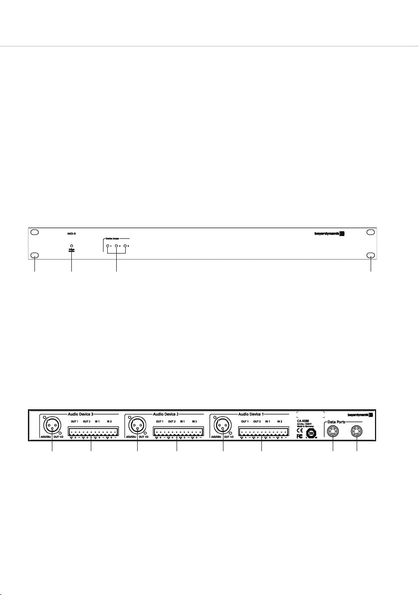
1. Anschluss- und Kontrollelemente
Vorderseite
Voltage-Monitor-LED
LED grün = normaler Betriebszustand
LED blinkt rot = Versorgungsspannung an den NetRateBus-Buchsen zu gering
Identifikations-LED
LED grün = zeigt an, welche der Interface-Einheiten (1-3) des CA 4588 gerade per Fernsteuerung
konfiguriert wird
Aussparung zur Befestigung in einem 19" Rack
Rückseite
AES/EBU Out
Der AES/EBU-Anschluss bietet 2 digitale Kanäle nach dem AES3 oder EBU Tech-3250E Standard.
Über diese XLR-Buchse werden die konfigurierbaren Audio-Kanäle (CH1 und CH2) mit festem
Pegel und einer Samplerate von 48 kHz ausgegeben.
Analoge Ein- und Ausgänge
2 symmetrische analoge Eingänge für Line-Pegel (6 dBu nominal) und 2 analoge Ausgänge mit
Line-Pegel (6dBu maximal). Die Signale werden über einen 12-poligen Phönix-Steckverbinder ge-
führt.
NetRateBus-Konferenzbuchsen zum Anschluss des Gerätes an die Steuerzentrale z.B. MCS-D 200

CA 4588 – Bedienung 5
deutsch
2. Anschlüsse
Netzwerkanschluss
• Verbinden Sie eine der beiden NetRateBus-Konferenzbuchsen mit der Steuerzentrale, z.B. MCS-D 200.
Das Digital/Analog-Interface CA 4588 wird dann über die Steuerzentrale mit Strom versorgt.
Audioanschluss digital
• An den AES/EBU-Ausgang können Sie z.B. digitale Audio-Aufnahmegeräte oder Mischpulte an-
schließen.
Audioanschluss analog
• An die analogen Eingänge der 12-poligen Phönix-Steckverbindung können Sie z.B. drahtlose
Mikrofone oder beliebige Wiedergabegeräte anschließen.
• An die analogen Ausgänge der 12-poligen Phönix-Steckverbindung können Sie z.B. Aufnahme-
geräte, Mischpult oder Mischverstärker mit symmetrischen Eingängen anschließen. Sollten Sie Geräte
mit unsymmetrischen Eingängen verwenden, müssen Sie eine elektrische Verbindung zwischen den
Pins „Cold“ und „Shield“ herstellen.
Belegung Phönixklemmen – Rückseite CA 4588
3. Konfiguration
Folgende Einstellungen müssen vorgenommen werden:
• Vergabe einer Identifikationsnummer (logische Adresse) für jede der drei Interface-Einheiten (DAI)
• Zuweisung von Kanälen für CH 1/2 IN (Eingänge) und CH 1/2 OUT (Ausgänge) der Interface-Einheiten
• Pegeleinstellung der CH 1/2 IN (Eingänge) und CH 1/2 OUT (Ausgänge)
• Ein-/Ausschalten (ON/OFF) der CH 1/2 IN (Eingänge) und CH 1/2 OUT (Ausgänge)
Achtung: Ungenutzte DAI-Eingänge müssen ausgeschaltet (OFF) sein, um Störgeräusche zu vermeiden!
Die Einstellungen können direkt an der Steuerzentrale MCS-D 200 im Menüpunkt DAI/DDI MANAGEMENT
oder über die Konferenzsoftware iCNS vorgenommen werden. Nähere Informationen entnehmen Sie
bitte der entsprechenden Bedienungsanleitung.
4. Version
CA 4588 Digital/Analog-Audiointerface, 6 IN, 6 OUT, 3 x Stereo-AES/EBU Out,
2 Push-Pull-Steckverbindungen, 19"-Gehäuse, 1 HE . . . . . . . . . . . . . . Best.-Nr. 722.677
CA 4588 – Aufbaubeispiele
6
6. Aufbaubeispiele
Nachfolgend finden Sie ein paar Beispiele, wie Sie den CA 4588 in ein Konferenzsystem, z.B. MCS-D 200
integrieren können.
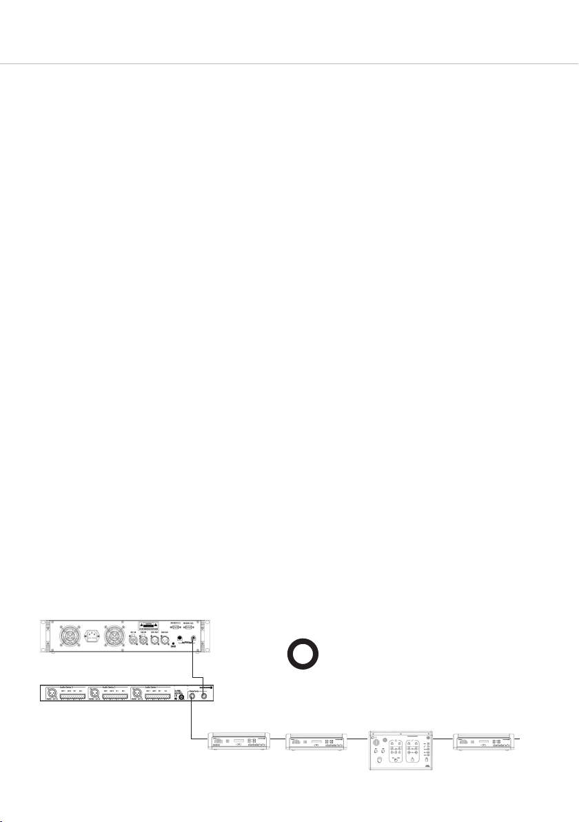
Einfügen von Geräten an beliebiger Stelle
Geräte wie Sprechstellen, Dolmetschersprechstellen und Digital / Analog Interfaces DAI werden einfach
an jeder beliebigen Stelle des Systems eingefügt.
Steuerzentrale MCS-D 200
Digital/Analog-Interface CA 4588
OK
MCS-D 31xx MCS-D 31xx
MCS-D 202
MCS-D 31xx
5. Technische Daten
Allgemeines
Abmessungen (B x H x T) . . . . . . . . . . . . 19" 1 HE (483 x 44 x 210 mm)
Gewicht . . . . . . . . . . . . . . . . . . . . . . . . . ca. 2,9 kg
Systemanschlüsse . . . . . . . . . . . . . . . . . . 2 x Push-Pull
Stromversorgung
Stromversorgung . . . . . . . . . . . . . . . . . . über Bussystem (48 V)
Leistungsaufnahme. . . . . . . . . . . . . . . . . max. 6,5 Watt (135 mA bei 48 V)
Analogeingänge
Anschlussbuchse. . . . . . . . . . . . . . . . . . . 12-polige Phönixbuchse (RM 5,08mm)
Pegel . . . . . . . . . . . . . . . . . . . . . . . . . . . 6 dBu maximal
Einstellbereich. . . . . . . . . . . . . . . . . . . . . 0 dB ... +22,5 dB
Eingangsimpedanz . . . . . . . . . . . . . . . . . 47 kΩ
Analogausgänge
Anschlussbuchse. . . . . . . . . . . . . . . . . . . 12-polige Phönixbuchse (RM 5,08 mm)
Pegel . . . . . . . . . . . . . . . . . . . . . . . . . . . 6 dBu maximal
Einstellbereich. . . . . . . . . . . . . . . . . . . . . -18 dB ... 0 dB
Ausgangsimpedanz . . . . . . . . . . . . . . . . 100 Ω
AES/EBU-Ausgänge
Anschlussbuchse. . . . . . . . . . . . . . . . . . . 3-polige XLR-Buchse
Sample-Rate . . . . . . . . . . . . . . . . . . . . . . 48 kHz
Analog Audio-Messwerte
(Eingang zu Ausgang, alle Regler auf 0 dB)
Frequenzgang. . . . . . . . . . . . . . . . . . . . . 20 Hz bis 20 kHz (-1 dB)
Rauschpegel . . . . . . . . . . . . . . . . . . . . . . -82 dBu (A-bewertet)
CA 4588 – Aufbaubeispiele 7
deutsch
1
6
7
5
4
8
3
9
2a
2
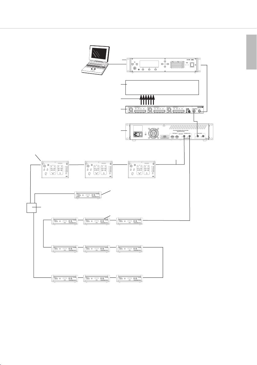
Aufbau mit Sprechstellen und Dolmetschersprechstellen
1 Steuerzentrale MCS-D 200
2 Delegiertensprechstelle MCS-D 3171
2a Präsidentensprechstelle MCS-D 3173
3 Dolmetschersprechstelle MCS-D 202, Hör-/Sprechgarnitur (oder Mikrofon und Kopfhörer)
4 Netzgerät CA 4146 , 6 A
5 Digital / Analog Interface CA 4588 (6 in / 6 out)
6 Z.B. externer Sender für drahtlose Übertragung
7 Kabel
8 Konferenzkabel CA 4302 (2 m, Push-Pull-Steckverbinder)
9 Adapter CA 4213 (T-Adapter)

CA 4588 – Aufbaubeispiele
8
1
6
7
5
OPERATOR
PC
SESSION 1
8
2a 2 3
4
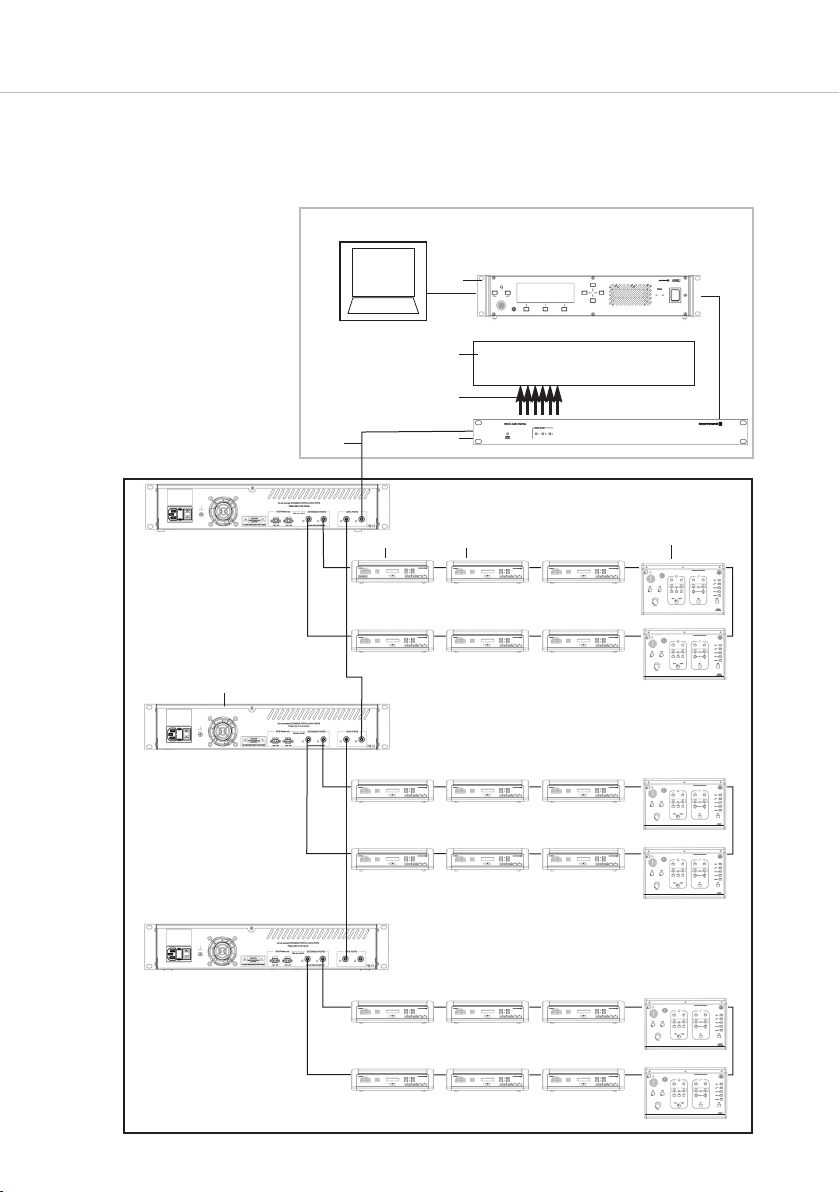
Multi-Session-Management
Alle Sprechstellen in Session 1

CA 4588 – Aufbaubeispiele 9
deutsch
1 Steuerzentrale MCS-D 200 (Push-Pull-Konferenzbuchse)
2 Delegiertensprechstellen MCS-D 3171 (Push-Pull-Konferenzbuchsen, Sprachenwähler, Abstim-
mungstasten, Display)
2a Präsidentensprechstelle MCS-D 3173 mit PRIORITY- und CLEAR-Funktionen (Rechte werden an
der MCS-D 200 zugewiesen), Push-Pull-Konferenzbuchsen, Sprachenwähler, Abstimmungstasten,
Display
3 Dolmetschersprechstelle MCS-D 202, Hör-/Sprechgarnitur (oder Mikrofon und Kopfhörer)
4 Netzgerät CA 4146 (6A)
5 Digital / Analog Interface CA 4588 (6 in/ 6 out)
6 Stationärer Sender Synexis TS für zusätzliche Empfänger
7 Kabel
8 Konferenzkabel CA 4302 (2 m, Push-Pull-Steckverbinder)

CA 4588 – Aufbaubeispiele
10
SESSION 1
SESSION 2
SESSION 3
1
6
7
5
PC
8
2a 2 3
4
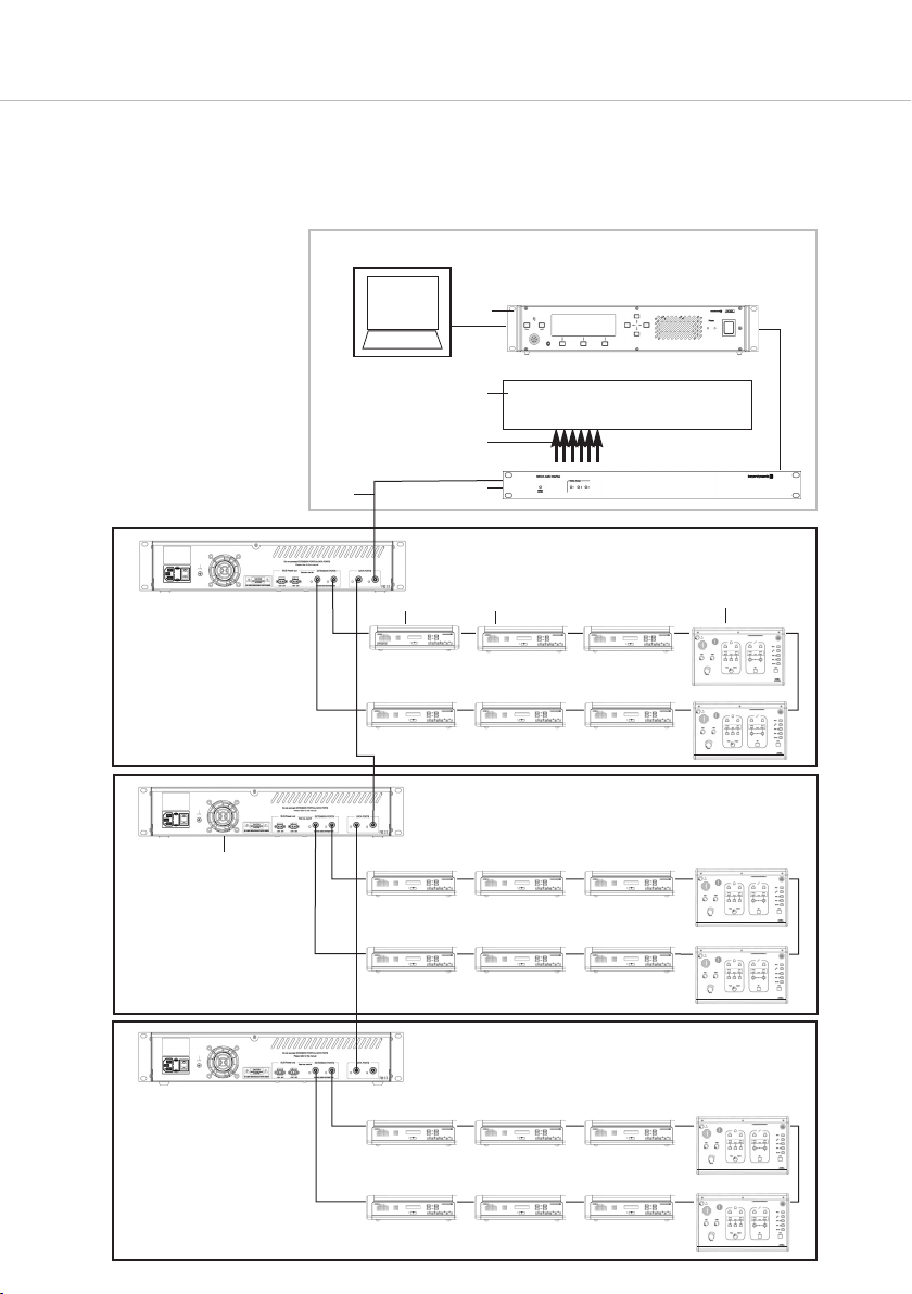
MultiSession Management

CA 4588 – Aufbaubeispiele 11
deutsch
MultiSession Management:
Mehrere verschiedene Sitzungen können gleichzeitig von einer einzigen Steuerzentrale MCS-D 200
und der Software iCNS aus gesteuert werden. Die einzelnen Sitzungsräume werden beliebig zu gro-
ßen Gruppen (Abb. Seite 10) oder zu einem einzigen großen Sitzungssaal (Abb. Seite 8) zusammen-
gefasst. Hierzu werden einfach nur Software-Einstellungen geändert.
1 Steuerzentrale MCS-D 200 (Push-Pull-Konferenzbuchse)
2 Delegiertensprechstellen MCS-D 3171 (Push-Pull-Konferenzbuchsen, Sprachenwähler,
Abstimmungstasten, Display)
2a Präsidentensprechstelle MCS-D 3173 mit PRIORITY- und CLEAR-Funktionen (Rechte werden an
der MCS-D 200 zugewiesen), Push-Pull-Konferenzbuchsen, Sprachenwähler, Abstimmungstasten,
Display
3 Dolmetschersprechstelle MCS-D 202, Hör-/Sprechgarnitur (oder Mikrofon und Kopfhörer)
4 Netzgerät CA 4146 (6A)
5 Digital / Analog Interface CA 4588 (6 in / 6 out)
6 Stationärer Sender Synexis TS für zusätzliche Empfänger
7 Kabel
8 Konferenzkabel CA 4302 (2 m, Push-Pull-Steckverbinder)

CA 4588 – Operation
12
OPERATING INSTRUCTIONS – CA 4588 Digital / Analogue Interface
The CA 4588 Digital / Analogue Interface extends the MCS-D conference system with audio inputs and
outputs. The CA 4588 is provided with 3 interface units each with 2 audio inputs (analogue) and 2 audio
outputs (analogue and digital).
You can connect external devices such as wireless microphones or reproducers to the inputs, and to the
outputs you can connect external devices such as recorders, mixing consoles or amplifiers.
The CA 4588 Digital / Analogue Interface is powered via the NetRateBus conference sockets and auto-
matically recognised by the system when connected to the control unit.
The interface units and audio channels are configured via the MCS-D 200 control unit or the iCNS
conference software.
1. Connectors and Indicators
Front view
Voltage Monitor LED
LED illuminates green to indicate the normal operation status
LED is flashing red to indicate that the supply voltage at the NetRateBus sockets is too low
Identification LED
LED illuminates green to indicate which of the interface units (1-3) of the CA 4588 is currently
configured
Holes for 19" rack mounting
Rear view
AES/EBU Out
The AES/EBU connection provides two digital channels according to the AES3 or EBU Tech-3250E
Standard. The configurable audio channels (CH1 and CH2) are transmitted via these XLR sockets
with a fixed level and a sample rate of 48 kHz.
Analogue inputs and outputs
Two balanced analogue inputs for line level (6 dBu nominal) and two analogue outputs with line
level (6dBu maximal). The signals are transmitted via a 12-pin Phoenix connector.
NetRateBus sockets for conference bus to connect to the control unit e.g. MCS-D 200

CA 4588 – Operation 13
english
2. Connections
Network connection
• Connect one of the NetRateBus sockets to the control unit e.g. MCS-D 200.
The CA 4588 Digital/Analogue Interface will be powered by the control unit.
Digital audio connection
• You can connect e.g. digital audio recorders or mixing consoles to the AES/EBU output .
Analogue audio connection
• You can connect e.g. wireless microphones or any reproducer to the analogue inputs of the 12-pin
Phoenix connector .
• You can connect e.g. recorders, mixinig consoles or amplifiers with balanced inputs to the analogue
outputs of the 12-pin Phoenix connector . If you use devices with unbalanced inputs, you must
establish an electrical connection between the “Cold” and “Shield” pins.
Pin assignment of Phoenix connectors on the rear of the CA 4588
3. Configuration
The following settings must be adjusted:
• Set an identification number (logical address) for each of the three interface units
• Assign channels for CH 1/2 IN (inputs) and CH 1/2 OUT (outputs) of the interface units
• Adjust the level of CH 1/2 IN (inputs) and CH 1/2 OUT (outputs)
• Switch on/off the CH 1/2 IN (inputs) and CH 1/2 OUT (outputs)
Warning: Unused DAI inputs must be OFF, to avoid noise!
You can adjust these settings in the DAI/DDI MANAGEMENT menus of the MCS-D 200 control unit or with
the iCNS conference software. For more information, please refer to the appropriate manuals.
4. Version
CA 4588 Digital/Analog Audio Interface, 6 IN, 6 OUT, 3 x Stereo-AES/EBU Out,
2 Push-Pull connectors, 19" housing, 1 U . . . . . . . . . . . . . . . . . . . . . . Order # 722.677
CA 4588 – Examples
14
6. Examples
In the following you will find some examples of how to integrate the CA 4588 into a conference system,
e.g. MCS-D 200.
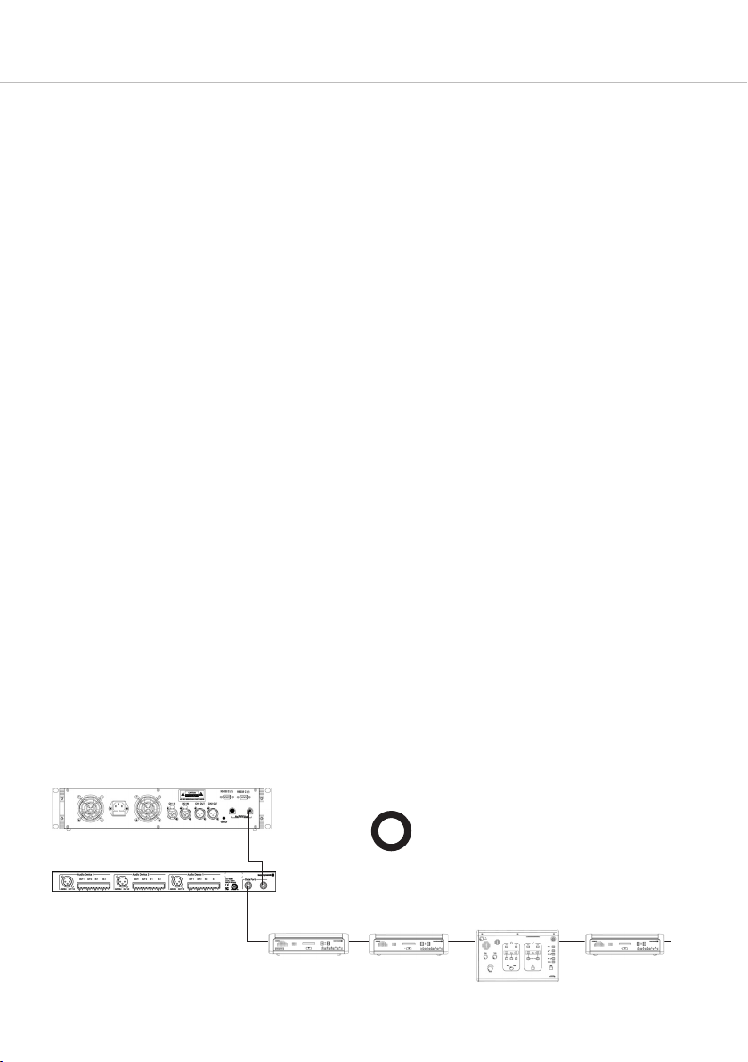
How to integrate devices at any location
Devices such as microphone stations, interpreter stations and digital / analogue interfaces are inserted
at any location of the system.
MCS-D 200 control unit
CA 4588 digital/analogue interface
OK
MCS-D 31xx MCS-D 31xx
MCS-D 202
MCS-D 31xx
5. Technical Specifications
General
Dimensions (W x H x D) . . . . . . . . . . . . . 19" 1 U (483 x 44 x 210 mm)
Weight . . . . . . . . . . . . . . . . . . . . . . . . . . approx. 2.9 kg
System connections . . . . . . . . . . . . . . . . 2 x push-pull
Power supply
Power supply . . . . . . . . . . . . . . . . . . . . . via bus system (48 V)
Power consumption . . . . . . . . . . . . . . . . max. 6.5 watt (135 mA at 48 V)
Analogue inputs
Connector . . . . . . . . . . . . . . . . . . . . . . . 12-pin Phoenix socket (RM 5.08 mm)
Level. . . . . . . . . . . . . . . . . . . . . . . . . . . . 6 dBu maximal
Range. . . . . . . . . . . . . . . . . . . . . . . . . . . 0 dB ... +22.5 dB
Input impedance. . . . . . . . . . . . . . . . . . . 47 kΩ
Analogue outputs
Connector . . . . . . . . . . . . . . . . . . . . . . . 12-pin Phoenix socket (RM 5.08 mm)
Level. . . . . . . . . . . . . . . . . . . . . . . . . . . . 6 dBu maximal
Range. . . . . . . . . . . . . . . . . . . . . . . . . . . -18 dB ... 0 dB
Output impedance . . . . . . . . . . . . . . . . . 100 Ω
AES/EBU outputs
Connector . . . . . . . . . . . . . . . . . . . . . . . 3-pin XLR socket
Sample rate . . . . . . . . . . . . . . . . . . . . . . 48 kHz
Measured analogue audio values
(input to output, all controls set to 0 dB)
Frequency response . . . . . . . . . . . . . . . . 20 Hz to 20 kHz (-1dB)
Noise level . . . . . . . . . . . . . . . . . . . . . . . -82 dBu (A-weighted)

CA 4588 – Examples 15
english
1
6
7
5
4
8
3
9
2a
2
Setup of the system with microphone stations and interpreter stations
1 MCS-D 200 control unit
2 MCS-D 3171 delegate station
2a MCS-D 3173 chairman station
3 MCS-D 202 interpreter station, headset (or microphone and headphone)
4 CA 4146 (6A) power supply unit
5 CA 4588 digital / analogue interface (6 in / 6 out)
6 Synexis TS stationary transmitter for additional receivers
7 Cable
8 CA 4302 conference cable (2 m, push-pull)
9 CA 4213 adapter
CA 4588 – Examples
16
1
6
7
5
OPERATOR
PC
SESSION 1
8
2a 2 3
4
MultiSession Management
All microphone stations in Session 1

CA 4588 – Examples 17
english
1 MCS-D 200 control unit (push-pull socket)
2 MCS-D 3171 delegate station (push-pull sockets, language selector, voting buttons, display)
2a MCS-D 3173 chairman station with PRIORITY and CLEAR buttons (configuration via MCS-D 200
control unit), push-pull sockets, language selector, voting buttons, display
3 MCS-D 202 interpreter station, headset (or microphone and headphone)
4 CA 4146 (6A) power supply unit
5 CA 4588 digital / analogue interface (6 in/ 6 out)
6 Synexis TS stationary transmitter for additional receivers
7 Cable
8 CA 4302 conference cable (2 m, push-pull)
CA 4588 – Examples
18
SESSION 1
SESSION 2
SESSION 3
1
6
7
5
PC
8
2a 2 3
4
MultiSession Management

CA 4588 – Examples 19
english
MultiSession Management:
Several meetings can be simultaneously controlled by one MCS-D 200 control unit and the iCNS
software. The individual conference rooms are combined to one large group (fig. page 18) or one
large conference room (fig. page 16). For this only software settings are changed.
1 MCS-D 200 control unit (push-pull socket)
2 MCS-D 3171 delegate station (push-pull sockets, language selector, voting buttons, display)
2a MCS-D 3173 chairman station with PRIORITY and CLEAR buttons (configuration via MCS-D 200
control unit), push-pull sockets, language selector, voting buttons, display
3 MCS-D 202 interpreter stations, headset (or microphone and headphone)
4 CA 4146 (6A) power supply unit
5 CA 4588 digital / analogue interface (6 in / 6 out)
6 Synexis TS stationary transmitter for additional receivers
7 Cable
8 CA 4302 conference cable (2 m, push-pull)
CA 4588 – Mise en service
20
NOTICE D’UTILISATION – Interface numérique / analogique CA 4588
L’interface numérique / analogique CA 4588 étend le système de conférence MCS-D avec des entrées
et sorties audio. CA 4588 offre 3 unités d’interface avec respectivement 2 entrées audio (analogiques)
et 2 sorties audio (analogique et numérique).
Sur les entrées, vous pouvez brancher des appareils externes tels que microphones sans fil ou lecteurs.
Sur les sorties, vous pouvez brancher des appareils externes tels qu’enregistreurs, pupitres de mixage ou
amplificateurs mixeurs.
L’interface numérique / analogique CA 4588 est alimentée en courant via les prises de conférence
NetRateBus et automatiquement identifiée par le système lors du raccordement à l’unité de contrôle.
Les unités d’interface et les canaux audio sont configurés via la centrale de commande MCS-D 200 ou
le logiciel de conférence iCNS.
1. Eléments de commande et de contrôle
Face avant
Moniteur DEL de tension
DEL allumée en vert = état de fonctionnement normal
DEL clignote en rouge = tension d’alimentation sur prises NetRateBus trop faible
Témoin DEL d’identification
DEL allumée en vert = affiche laquelle des unités d’interface (1-3) du CA 4588 est en train d’être
configurée par commande à distance
Evidement pour le montage dans un rack 19"
Face arrière
Sortie AES/EBU
Le port AES/EBU offre 2 canaux numériques selon standard AES3 ou EBU Tech-3250. Via ce
connecteur XLR, les canaux audio configurables (CH1 et CH2) sont restitués avec un niveau fixe
et un taux d’échantillonnage de 48 kHz.
Entrées et sorties analogiques
2 entrées analogiques symétriques pour niveau de ligne (6 dBu nominal) et 2 sorties analogiques
avec niveau de ligne (6 dBu maximum). Les signaux sont dirigés via un connecteur Phoenix 12
broches.
Prises conférence NetRateBus pour raccordement à la centrale de commande, p. ex. MCS-D 200
Table of contents
Languages:
Other Beyerdynamic Recording Equipment manuals


