Configuration
3.1.2 Setting the PC interrupt
The required interrupt can be set separately for each CAN controller. The Interrupt num-
ber and the number of the associated CAN controller are located on the board under
the two jumper boards. The required PC interrupt is set with the corresponding jumper
board by closing the jumper pair of the required IRQ.
Only one interrupt may be selected for each CAN controller. If no interrupt is required,
no pin of the corresponding jumper board may be bridged. The factory setting of the
interface is IRQ5 for the first CAN controller and (if present) IRQ10 for the second CAN
controller (see Fig. 3-1). It must be ensured that no other system components occupy
the selected interrupt, except for system components that work with shared interrupts.
3.1.3 READY signal
With assembled Intel 82527 the READY signal can be supported with the DIP switch
SW1-7. For this the switch is set to OFF (factory setting: Switch SW1-7 set to ON). The
READY signal is used when an error occurs during a read accesses on the Intel CAN
controller (wrong index contents).
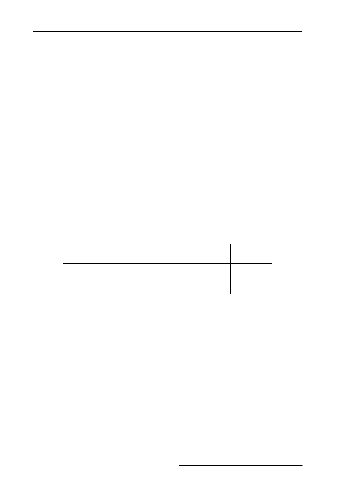
3.1.4 Supplying voltage via CAN connector
VCC or GND can be connected to the 9-pin Sub-D connector/socket with the soldered
jumpers JP3, JP4, JP5, JP32, JP33 and JP36. For this the jumpers listed in the following
table must be closed. The soldered jumpers are located on the back of the PC-I 03.
Connector board pin
(JP15/JP25) - Signal
Default
setting
CAN
line 1
CAN
line 2
3 - GND closed JP3 JP32
6 - GND open JP5 JP33
9 - VCC open JP4 JP36
Caution: This voltage may be loaded with maximum 100 mA.
With galavanically isolated bus interfaces, GND and VCC are also galvanically isolated
from the power supply of the PC.
3.1.5 Bus terminal
Bus terminal resistors are assembled on the PC-I 03 for the first and second CAN line
with 120 Ohms each. The bus terminal for the first CAN line is connected with the sol-
dered jumper JP6, for the second CAN line with JP7. The bus is terminated between
CAN-Low and CAN-High. When delivered, the bus terminals are not active.
3.2 Design of the CAN connectors
Two isolated high-speed bus interfaces according to ISO 11898-2 can be mounted on
the interface.
The signals of the first bus interface are connected to the 9-pin Sub-D connector/socket.
If the second bus interface is assembled, the signals for the CAN bus of the second bus
Copyright IXXAT Automation GmbH PC-I 03 - Manual, Version 3.2
10