BFT PHEBE BT A U User manual

ISTRUZIONI D’USO E DI INSTALLAZIONE
INSTALLATION AND USER’S MANUAL
INSTRUCTIONS D’UTILISATION ET D’INSTALLATION
INSTALLATIONS-UND GEBRAUCHSANLEITUNG
INSTRUCCIONES DE USO Y DE INSTALACION
INSTALLATIEVOORSCHRIFTEN
MOTORIZZAZIONE PER PORTE BASCULANTI A CONTRAPPESO
MOTOR DRIVES FOR COUNTER-BALANCED OVERHEAD DOORS
MOTORISATIONS POUR PORTES DE GARAGE A CONTREPOIDS
ANTRIEBE FÜR GEGENGEWICHT-GARAGENTORE
MOTORIZACION PARA PUERTAS BASCULANTES DE CONTRAPESOS
MOTORAANDRIJVING VOOR KANTELDEUREN MET TEGENGEWICHT
Attenzione! Leggere attentamente le“Avvertenze”all’interno! Caution! Read“Warnings”inside carefully! Attention! Veuillez lire attentivement les Avertissements qui se trouvent à l’intérieur!
Achtung! Bitte lesen Sie aufmerksam die„Hinweise“ im Inneren! ¡Atención¡ Leer atentamente las“Advertencias”en el interior! Let op! Lees de“Waarschuwingen”aan de binnenkant zorgvuldig!
D812841 00100_05 13-12-22
PHEBE BT A U
PHEBE ULTRA BT A

a) Prima di iniziare con l’installazione bisogna leggere le avvertenze.
a) Before commencing installation, make sure you read the warnings.
a) Avant de commencer l’installation lisez les avertissements.
a) Vor der Installation müssen die Hinweise gelesen werden.
a) Antes de comenzar con la instalación es necesario leer las adver-
tencias.
a) Voor met de installatie te beginnen moet u de waarschuwingen lezen.
b) Oltre alle gure, bisogna seguire le indicazioni date nel MANUALE PER L’INSTALLAZIONE.
b) In addition to the gures, you must follow the instructions given in the INSTALLATION MANUAL.
b) Suivez non seulement les gures mais aussi les indications données dans le
MANUEL D’INSTALLATION.
b)
Außer den Abbildungen müssen die Angaben im entsprechenden Abschnitt auf MONTAGEANLEITUNG werden
.
b) Además de las guras, es necesario seguir las indicaciones dadas en MANUAL DE INSTALACIÓN.
b) Volg niet alleen de guren, maar ook de aanwijzingen die in INSTALLATIEHANDLEIDING.
INSTALLAZIONE VELOCE-QUICK INSTALLATION-INSTALLATION RAPIDE
SCHNELLINSTALLATION-INSTALACIÓN RÁPIDA - SNELLE INSTALLATIE
C
B
A
12 6
M8
V1
V2
V2
1
V1
V1
3
70-80 mm
1
2
V1
a=b
b
a
3
4
5
5
40 M6
M6
V2
V2
D1
D1
2
615 870
870 615
100
V2
13
ST3,9
V1
ST 3.5
22 5.5 10 10
Ø 4
TX
5x0,75 mm2
RX
2x0,75 mm2
RG58
2x0,75 mm
2
2x1,5mm
2
(L-N)
3x1,5 mm
2
3x0,75 mm
2
(L-N-GND)
4mm
13mm
25N max
Non in dotazione
Not supplied
Ne sont pas fournis
Nicht im lieferum
No asignadas en el equipamiento base
Niet meegeleverd
2 - PHEBE BT A U - PHEBE ULTRA BT A
D812841 00100_05

ENGLISH FRANÇAIS ESPAÑOL
NEDERLANDS
DEUTSCHITALIANO
F
HG
X
X= >15 mm
X= <15 mm
1/2 1/2 Y=60
X=35
D
2.5 mm
1/21/2
45°
E
1
2
PHEBE BT A U - PHEBE ULTRA BT A - 3
D812841 00100_05

M
L
K
V1
50
M6
D1
M6
10
10
V1
D1
1
2
3
I
1
2
J
25mm 30mm
70mm
25 mm
>70-80 mm
D
D
D
D
1
Ø7
Ø6
4 - PHEBE BT A U - PHEBE ULTRA BT A
D812841 00100_05

OPQ
C
1/3 H1/3 H1/3 H
150mm
PHEBE BT A U C
H
1/2 H1/2 H
110 mm
114mm
249 mm 330 mm
579 mm
113mm
133 mm
160 mm
N
CLICK
CLICK
PHEBE BT A U - PHEBE ULTRA BT A - 5
D812841 00100_05

T
1
RS
1
PHEBE BT A SQ
PHEBE BT A SQ
PHEBE BT A SQ
VEGA CPEL
VEGA CPEL
2x2,5mm
2
*
2x2.5 mm
2
* + 3x0.75 mm
2
2x0.75 mm
2
**
2x0.75 mm
2
***
2x2.5 mm
2
* + 3x0.75 mm
2
2x0.75 mm
2
**
2x0.75 mm
2
***
2x2,5 mm
2
*
2x2.5 mm
2
*
L-N 2x1.5mm2
L-N 2x1.5mm2
L-N 2x1.5mm2
L-N 2x1.5mm2
L-N 2x1.5mm2
L-N 2x1.5mm2
L-N 2x1.5mm2
L-N 2x1.5mm2
PHEBE BT A U
2x2.5 mm
2
*
2x0.75 mm
2
2x0.75 mm
2
**
2x0.75 mm
2
***
PHEBE BT A U
PHEBE BT A SQ
2x2.5 mm
2
*
2x2.5 mm
2
*
2x0.75 mm
2
2x0.75 mm
2
**
2x0.75 mm
2
***
2x2.5 mm
2
*
PHEBE ULTRA BT A
VEGA CPEL
2x2.5 mm
2
* + 3x0.75 mm
2
2x0.75 mm
2
**
2x0.75 mm
2
***
2x2.5 mm
2
*
PHEBE ULTRA BT A SQ
2x2.5 mm
2
* + 3x0.75 mm
2
2x0.75 mm
2
**
2x0.75 mm
2
***
VEGA CPEL
2x2,5 mm
2
*
2x2.5 mm
2
*
3x0.75 mm
2
2x0.75 mm
2
**
2x0.75 mm
2
***
PHEBE ULTRA BT A SQ
PHEBE ULTRA
BT A SQ
2x2.5 mm
2
*
2x2.5 mm
2
*
3x0.75 mm
2
2x0.75 mm
2
**
2x0.75 mm
2
***
PHEBE ULTRA BT A
PHEBE ULTRA BT A SQ
= 2,5mm2 10m max. = Optional per luce di cortesia
Optional per luce di cortesia
= Optional per pulsante di START
Optional per pulsante di START
2
3
4
1
2
3
4
6 - PHEBE BT A U - PHEBE ULTRA BT A
D812841 00100_05

1) GENERALITÀ
Progettato per motorizzare porte basculanti a contrappesi.
La compattezza e la versatilità di montaggio rendono la motorizzazione appli-
cabile in qualsiasi modello di basculante, sia a montaggio centrale che laterale.
È consigliato per uso residenziale.
Il riduttore di tipo irreversibile, mantiene la porta bloccata in chiusura senza
l’impiego di elettroserrature.
Nel caso manchi l’alimentazione di rete, lo sblocco si attiva dall’interno con una
apposita manopola. É dotato di necorsa (PHEBE BT A U) che arrestano il motore
sia in apertura che in chiusura e di luce di cortesia temporizzata.
La versione PHEBE ULTRA BT A è invece dotata di sensore di posizione integrato
nella centrale con regolazione da display della posizione di chiusura e apertura.
Versioni disponibili:
PHEBE BT A U / PHEBE BT A U IP44
Versione con centralina (VEGA) incorporata adatta a comandare uno o due
operatori. Versione IP 20 o IP44.
PHEBE BT A SQ /PHEBE BT A SQ IP44
Versione senza centralina di comando, indispensabile per automazioni con due
attuatoriPHEBE dicuiilprimoèPHEBEBTA U,ilsecondoè PHEBEBTASQ.Possono
essere impiegati anche quando interessa avere la centralina montata a parete.
Versione IP 20 o IP44.
PHEBE ULTRA BT A
VersioneaventegradodiprotezioneIP44econcentralina(VEGAULTRA)incorporata
adatta a comandare uno o due operatori. La centrale VEGA ULTRA è dotata di un
sensore di posizione integrato con regolazione da display della posizione di
chiusura e apertura.
PHEBE ULTRA BT A SQ
Versionesenzacentralinadicomando,congradodiprotezioneIP44,indispensabile
per automazioni con due attuatori PHEBE ULTRA di cui il primo è PHEBE ULTRA
BT A, il secondo è PHEBE ULTRA BT A SQ.
Possono essere impiegati anche quando interessa avere la centralina montata a
parete e controllo di posizione a display.
PHEBE BT A U C
Versione per basculanti a telo snodato con centralina (VEGA) incorporata adatta
a comandare uno o due operatori. Grado di protezione IP20.
PHEBE BT A C SQ
Versioneperbasculantiatelosnodato,senzacentralinadicomando,indispensabile
per automazioni con due attuatori PHEBE C di cui il primo è PHEBE BT A U C, il
secondo è PHEBE BT A C SQ. Possono essere impiegati anche quando interessa
avere la centralina montata a parete. Grado di protezione IP20.
PHEBE BT A U KIT
Versione disponibile in kit; adatta per porte basculanti no a 7m2di telo, dispone
di centralina incorporata Mod. VEGA.
ATTENZIONE:Glioperatori che non hanno lacentralinaabordo,devonoessereco-
mandaticonunacentralinadotatadi regolazioneelettronicadicoppia (serieVEGA).
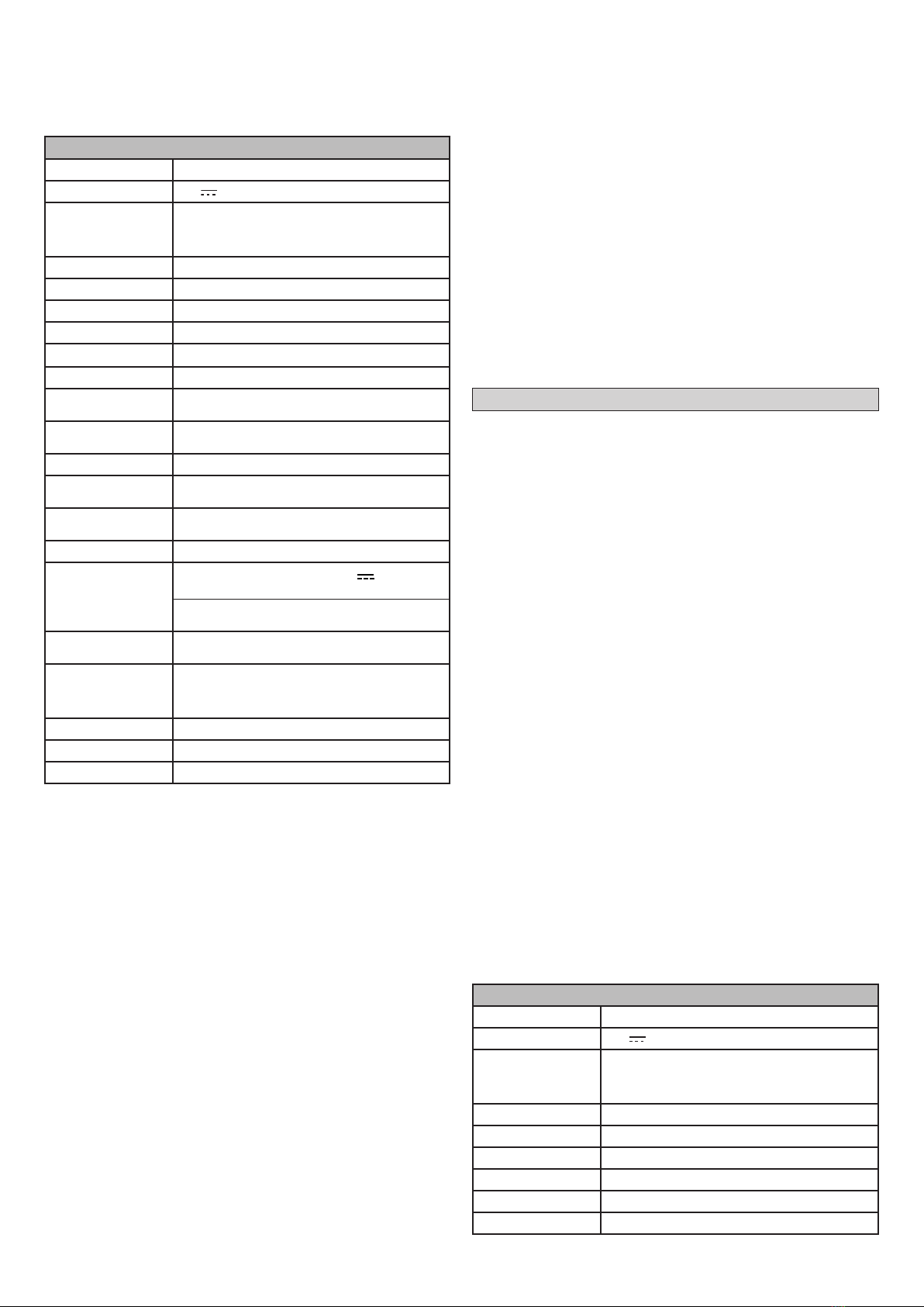
2) DATI TECNICI
MOTORE
Alimentazione 220-230V~ 50/60 Hz
Motore 24V 1500 min-1
Potenza massima
PHEBEBTAU/PHEBEBTAU IP44/PHEBEULTRA
BT A/ PHEBE BT A U C: 130W
PHEBE BT A SQ / PHEBE BT A SQ IP44 / PHEBE
BT A C SQ: 70W
Classe isolamento F
Lubricazione Grasso permanente
Albero uscita Albero cavo passante 20X20
Tempo apertura 17 ÷ 20 s
Coppia fornita 300Nm (tutte le versioni)
Limiti impiego 1 Motore X 8m2/ 2 Motori X 12m2
Reazione all’urto Limitatore di coppia integrato su quadro di
comando VEGA
Finecorsa
Elettrici incorporati e regolabili (PHEBE BT A U)
Sensorediposizioneintegrato(PHEBEULTRABTA)
Manovra manuale Sblocco a manopola
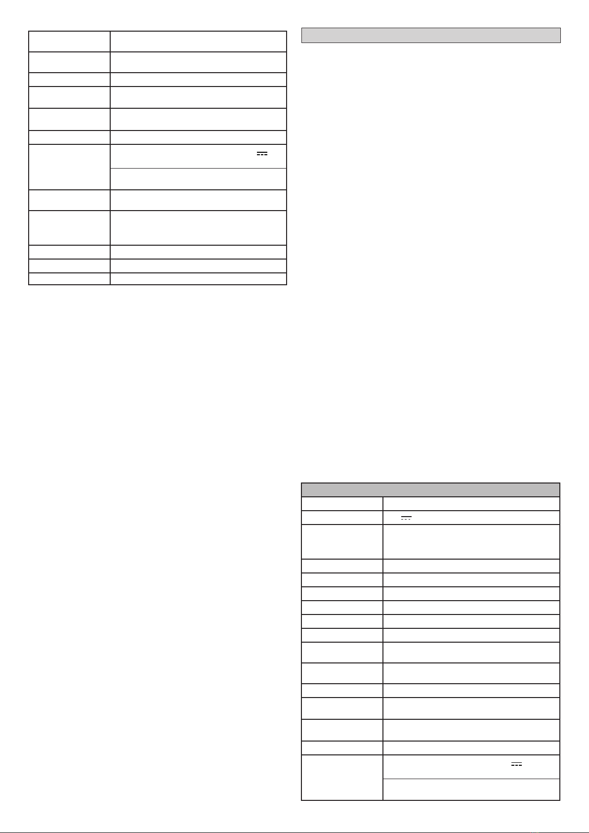
Manovrein24ore @MAX+55°C
500
Manovrein1ora@MAX+55°C 20
Tipo di utilizzo Intensivo
Luce di cortesia Lampadina a led di cortesia mod. BFT 24V
(PHEBE BT A U - PHEBE BT A U C)
Scheda luce di cortesia mod. BFT
(PHEBE BT A U IP44 - PHEBE ULTRA BT A)
Temperatura di utilizzo
-15 + 55° C (tutte le versioni)
Parti elettriche: -15 + 55° C
Grado di protezione PHEBE BT A U / PHEBE BT A SQ / PHEBE BT A U
C / PHEBE BT A C SQ: IP20
PHEBE BT A U IP44 / PHEBE BT A SQ IP44 /
PHEBEULTRABTA / PHEBE ULTRA BTASQ:IP44
Peso operatore 10kg (≈100N)
Dimensioni Vedi Fig. O
Pressione acustica <70dBA
(*) Tensioni speciali di alimentazione a richiesta.
3) MONTAGGIO ATTUATORE SU BASE FIG.B
NOTA: si consiglia di applicare la copertura dell’attuattore solo ad installazione
ultimata utilizzando le quattro viti.
4) MONTAGGIO SU PORTA MOTORE E ALBERI DI TRASMISSIONE FIG. C
ATTENZIONE: devono essere ssati saldamente al telaio della porta basculante
e perfettamente in asse con il foro dell’albero dell’attuatore Rif.3.
L’alberoditrasmissionedeveesserebloccatosull’operatorestringendoleapposite
viti. (Tramite perno su albero per PHEBE BT A U C).
5) TAGLIO TUBI ECCEDENTI FIG. D
6) BILANCIAMENTO PORTA FIG. E
Rif.1) BILANCIAMENTO CORRETTO: la porta a 45° (sbloccata) rimane FERMA.
Rif.2) Se i contrappesi sono in ferro ssarli con saldatura. Se la porta tende a
scendere, aggiungere peso ai contrappesi.
7) MONTAGGIO BRACCI TELESCOPICI FIG. F-G-H-I-J
ATTENZIONE: Prima di farruotarel’alberodell’attuatore,vericareche le camme,
che comandano i micro-necorsa, ruotino liberamente (allentarle) (versione
PHEBE BT A U).
Fig. G-H) Fissaggio attacco superiore
Fig. I) Misurazione e taglio bracci telescopici
Tagliare i bracci telescopici rispettando le quote “D” su:
- Rif.1) Bracci dritti
- Rif.2) Bracci curvi.
Fig. J) Vericare che, a porta chiusa, il braccio telescopico rimanga inserito
per almeno 70-80 mm.
ATTENZIONE: incasononsirispetti questacondizioneindividuareuna
posizione dell’attacco “A” più idonea o adottare dei bracci più lunghi.
8) ACCOPPIAMENTO ALBERO TELESCOPICO E TUBI TRASMISSIONE FIG. K
9) IMPIANTO ELETTRICO FIG. L - M
Iltratto di cavitra parete eportamobile, deve avereun’ansa (Fig.M Rif.1)sucien-
temente lunga da permettere il movimento della porta senza essere sottoposta
a tensionamento.
ATTENZIONE: proteggere il cavo da bordi taglienti durante l’installazione.
10) REGOLAZIONE FINECORSA
PHEBE BT A U: Vedere g. N
PHEBE ULTRA BT A: Vedere manuale della centrale VEGA- VEGA ULTRA
11) INSTALLAZIONE SU BASCULANTI A GUIDE VERTICALI E ORIZZONTALI
FIG. P
12) INSTALLAZIONE SU BASCULANTI CON TELO SNODATO (PHEBE BT A U C
/ PHEBE BT A C SQ) FIG. Q
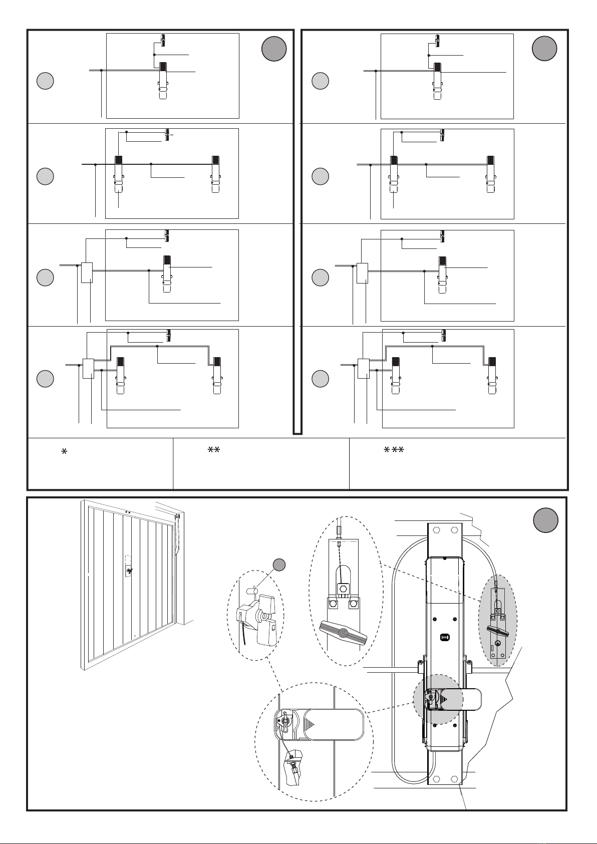
13) CONFIGURAZIONI E COLLEGAMENTI PHEBE BT A U FIG. R
Rif.1) n°1 PHEBE BT A U o n°1 PHEBE BT A U KIT con centralina a bordo
Rif.2) n°1PHEBEBTAUconcentralinaabordoen°1PHEBEBTASQsenzacentralina
Rif.3) n°1 PHEBE BT A SQ con centralina a parete (mod. VEGA CPEL)
Rif.4) n°2 PHEBE BT A SQ con centralina a parete (mod. VEGA CPEL)
14) CONFIGURAZIONE E COLLEGAMENTI PHEBE ULTRA BT A FIG.S
Rif.1) n°1 PHEBE ULTRA BT A con centralina a bordo
Rif.2) n°1 PHEBE ULTRA BT A con centralina a bordo e n°1 PHEBE ULTRA BT A SQ
senza centralina
Rif.3) n°1 PHEBE ULTRA BT A SQ con centralina a parete (mod. VEGA CPEL)
Rif.4) n°2 PHEBE ULTRA BT A SQ con centralina a parete (mod. VEGA CPEL)
15) SBLOCCO MANUALE (Vedi MANUALE D’USO -FIG.1)
ACCESSORIO PER SBLOCCO ESTERNO FIG.T
Nelcaso si montilo sblocco dall’esterno,è necessario caricarela molla dirichiamo
della leva di sblocco.
1) FOREWORD
Designed to drive counterweight overhead doors.
Its compact design and mounting versatility mean the drive can be applied in
any overhead model, tted either centrally or at the side. It is recommended for
residential use.
The irreversible gearbox keeps the door locked closed without the use of sole-
noid locks.
If the event of a mains power outage, the release is operated from the inside by
means of a special knob. It features limit switches (PHEBE BT A U) that stop the
motor both on opening and closing as well as a timed courtesy light.
The PHEBE ULTRA BT A version is equipped with a position sensor built into the
controlunitwithadjustment oftheopeningandclosing positionfromthedisplay.
Available versions:
PHEBE BT A U / PHEBE BT A U IP44
Version with built-in control panel (VEGA) suitable for controlling one or two
operators. Version IP 20 or IP44.
PHEBE BT A SQ /PHEBE BT A SQ IP44
Version with no control panel, essential for automated systems with two PHEBE
actuators where the rstis a PHEBE BTA U and the second aPHEBE BT A SQ. Can also
be used when you want to mount the control panel on a wall.Version IP 20 or IP44.
PHEBE ULTRA BT A
Version with IP44 protection and built-in control unit (VEGA ULTRA) suitable to
control one or two operators. The VEGA ULTRA control unit is equipped with a
built-in position sensor with adjustment of the opening and closing position
from the display.
PHEBE ULTRA BT A SQ
Versionwithoutcontrolunit,withIP44 protection, indispensable for automations
with two PHEBE ULTRA actuators, the rst one being a PHEBE ULTRA BT A, the
second a PHEBE ULTRA BT A SQ.
They can be used also when the control unit must be wall-tted and the position
controlled from the display.
PHEBE BT A U C
Version for bi-fold overhead doors with built-in control panel (VEGA) suitable
for controlling one or two operators. Protection rating IP20.
PHEBE BT A C SQ
Version for bi-fold overhead doors with no control panel, essential for automated
systems with two PHEBE C actuators where the rst is a PHEBE BT A U C and the
second a PHEBE BT A C SQ. Can also be used when you want to mount the control
panel on a wall. Protection rating IP20.
MANUALE PER L’INSTALLAZIONE
INSTALLATION MANUAL
PHEBE BT A U - PHEBE ULTRA BT A - 7
D812841 00100_05

PHEBE BT A U KIT
Version available as a kit. Suitable for overhead doors with leaf measuring up to
7m2, has built-in control panel Mod. VEGA.
WARNING: Operators without a built-in control panel must be controlled with a
control panel featuring electronic torque control (VEGA series).
2) TECHNICAL SPECIFICATIONS
MOTOR
Power supply 220-230V~ 50/60 Hz
Motor 24V 1500 min-1
Maximum power
PHEBE BT A U/ PHEBE BT A U IP44/PHEBE ULTRA BT A
/ PHEBE BT A U C: 130W
PHEBE BT A SQ / PHEBE BT A SQ IP44 / PHEBE BT A
C SQ: 70W
Insulation class F
Lubrication Lifetime greased
Output shaft Hollow through shaft 20X20
Opening time 17 ÷ 20 s
Supplied torque 300Nm (all versions)
Operating limits 1 Motor for 8m2/ 2 Motor for 12m2
Impact reaction Torque limiter built into VEGA control panel
Limit switches Electrical built-in and adjustable (PHEBE BT A U)
Built-in position sensor (PHEBE ULTRA BT A)
Manual operation Knob-operated release
Manoeuvres in 24
hours@ MAX+55°C 500
Manoeuvresin1hour@
MAX+55°C 20
Type of use intensive
Courtesy light BFT model courtesy LED lamp 24V
(PHEBE BT A U - PHEBE BT A U C)
BFT model courtesy light board
(PHEBE BT A U IP44 - PHEBE ULTRA BT A)
Operating temperatu-
re range -15 + 55° C (all versions)
Electrical parts: -15 + 55° C
Protection rating
PHEBE BT A U / PHEBE BT A SQ / PHEBE BT A U C /
PHEBE BT A C SQ: IP20
PHEBE BT A U IP44 / PHEBE BT A SQ IP44 / PHEBE
ULTRA BT A / PHEBE ULTRA BT A SQ: IP44
Operator weight 10kg (≈100N)
Dimensions See Fig. O
Sound pressure <70dBA
(*) Special supply voltages to order.
3) MOUNTING THE ACTUATOR ON BASE FIG.B
NOTE: it is advisable to wait until installation is complete before tting the
actuator’s cover using the four screws.
4) MOUNTING THE MOTOR AND DRIVE SHAFTS ON DOOR FIG. C
WARNING:they must be fastened securely to theframe of the overhead door and
must be perfectly aligned with the centre of the hole in the actuator’s shaft Ref.3.
The drive shaft must be blocked on the operator, with the appropriate screws.
(Using the shaft pin for PHEBE BT A U C)
5) CUTTING EXCESS TUBES FIG. D
6) DOOR BALANCING Fig. E
Rif.1) BCORRECTLY BALANCED: when at 45° (released) the door is UNMOVING.
Rif.2) If the counterweights are made of iron, weld them on. If the door tends to
lower, add weight to the counterweights.
7) TELESCOPIC ARM ASSEMBLY FIG. F-G-H-I-J
ATTENTION: Before turning the actuator’s shaft, make sure the cams controlling
the limit microswitches turn freely (loosen them) (PHEBE BT A U version).
Fig. G-H) Fastening the upper tting
Fig. I) Measuring and cutting telescopic arms
Cut the telescopic arms, keeping to the distances “D”on:
- Ref.1) Straight arms
- Ref.2) Curved arms.
Fig. J) Make sure that, with the door closed, the telescopic arm is still 70-80
mm inside.
WARNING: if this is not the case, identify a more suitable position for
tting “A” or use longer arms.
8) COUPLING TELESCOPIC SHAFT AND DRIVE TUBES FIG. K
9) ELECTRICAL SYSTEM FIG. L - M
The length of cable between the wall and moving door must have a suciently
long loop (Fig.M Ref.1) to allow for the door to move without the cable being
pulled taut.
ATTENTION: protect the cable from sharp edges during installation.
MANUEL D’INSTALLATION
10) LIMIT SWITCH ADJUSTMENT
PHEBE BT A U: See g. N.
PHEBE ULTRA BT A: See the VEGA – VEGA ULTRA control unit manual.
11) INSTALLATION ON OVERHEAD DOORS WITH VERTICAL AND HORIZON-
TAL GUIDES FIG. P
12) INSTALLATION ON BI-FOLD OVERHEAD DOORS (
PHEBE BT A U C / PHEBE
BT A C SQ
) FIG. Q
13) PHEBE BT A U CONFIGURATION AND WIRING FIG. R
Rif.1) No. 1 PHEBE BT A U or No. 1 PHEBE BT A U KIT with control unit on board
Rif.2) No. 1 PHEBE BT A U with control unit on board and No. 1 PHEBE BT A SQ
without control unit
Rif.3) No. 1 PHEBE BT A SQ with wall-mounted control panel (mod. VEGA CPEL)
Rif.4) No. 2 PHEBE BT A SQ with wall-mounted control panel (mod. VEGA CPEL)
14) PHEBE ULTRA BT A CONFIGURATION AND WIRING FIG. S
Rif.1) No. 1 PHEBE ULTRA BT A with control unit on board
Rif.2) No. 1 PHEBE ULTRA BT A with control unit on board and No. 1 PHEBE ULTRA
BT A SQ without control unit
Rif.3) No. 1 PHEBE ULTRA BT A SQ with wall-mounted control panel (mod. VEGA
CPEL)
Rif.4) No. 2 PHEBE ULTRA BT A SQ with wall-mounted control panel (mod. VEGA
CPEL)
15) MANUAL RELEASE (See USER GUIDE -FIG.1)
ACCESSORY FOR EXTERNAL RELEASE FIG.T
If the release device is being mounted on the outside, you will need to wind the
release lever’s return spring.
1) GÉNÉRALITÉS
Conçu pour motoriser les portes basculantes à contrepoids.
Grâce à sa forme compacte et à son montage versatile la motorisation peut
s’installer sur n’importe quelle porte basculante, au milieu ou sur le côté. Nous
conseillons un usage résidentiel.
Leréducteurréversiblepermetdeverrouiller laporteunefois ferméesansrecourir
à une serrure électrique.
En cas de panne de courant, le déverrouillage s’active de l’intérieur à l’aide d’une
poignée prévue à cet eet. Il est muni de ns de course (PHEBE BT A U) qui
arrêtent le moteur aussi bien à portail ouvert qu’à portail fermé et d’une lampe
de courtoisie munie de minuterie.
Par contre la version PHEBE ULTRA BT est équipée d’un capteur de position
intégré à la centrale avec réglage de la position de fermeture et d’ouverture à
partir de l’acheur.
Versions disponibles:
PHEBE BT A U/ PHEBE BT A U IP44
Version avec centrale (VEGA) intégrée, en mesure de commander deux action-
neurs. Version IP 20 ou IP44.
PHEBE BT A SQ /PHEBE BT A SQ IP44
Version sans centrale de commande, indispensable avec les automatisations
équipéesdedeuxactionneursPHEBE,dontlepremierestPHEBEBTAUetlesecond
PHEBEBTA SQ.On peut aussi les employer si l’on désire avoir une centrale murale.
Version IP 20 ou IP44.
PHEBE ULTRA BT A
Version avec degré de protection IP44 et centrale (VEGA ULTRA) intégrée en
mesure de commander un ou deux actionneurs. La centrale VEGA ULTRA est
équipée d’un capteur de position intégré à la centrale avec réglage de la position
de fermeture et d’ouverture à partir de l’acheur.
PHEBE ULTRA BT A SQ
Versionsans centraledecommande,avecdegrédeprotectionIP44, indispensable
pour les automatisations équipées de deux actionneurs PHEBE ULTRA, dont le
premier est PHEBE ULTRA BT A et le deuxième PHEBE ULTRA BT A SQ.
On peut aussi les employer si l’on désire avoir une centrale murale et le contrôle
de la position sur l’acheur.
PHEBE BT A U C
Version pour basculante à bâti articulé avec centrale (VEGA) intégrée, en mesure
de commander un ou deux actionneurs. Degré de protection IP20.
PHEBE BT A C SQ
Versionpourbasculanteàbâtiarticulé,sanscentraledecommande,indispensable
avec les automatisations équipées de eux actionneurs PHEBE C, dont le premier
est PHEBE BT A U C et le second PHEBE BT A C SQ. On peut aussi les employer si
l’on désire avoir une centrale murale. Degré de protection IP20.
PHEBE BT A U KIT
Version disponible en kit, pour les portes basculantes dont le bâti mesure jusqu’à
7m2, dispose de centrale intégrée Modèle mesurant VEGA.
ATTENTION: Les actionneurs dépourvus de centrale à bord doivent être com-
mandés à l’aide d’une centrale munie de régulateur de couple électronique
(série VEGA).
2) DONNÉES TECHNIQUES
MOTEUR
Alimentation 220-230V~ 50/60 Hz
Moteur 24V 1500 min-1
Puissance maximum
PHEBE BT A U / PHEBE BT A U IP44 / PHEBE ULTRA BT
A/ PHEBE BT A U C:130W
PHEBE BT A SQ / PHEBE BT A SQ IP44 / PHEBE BT A
C SQ: 70W
Classe d’isolation F
Lubrication Graisse permanente
Arbre sortie Arbre creux passant 20x20
Temps d’ouverture 17 ÷ 20 s
Couple fourni 300Nm (toutes les versions)
Limites d’utilisation 1 Moteur pour 8m2/ 2 Moteurs pour 12m2
8 - PHEBE BT A U - PHEBE ULTRA BT A
D812841 00100_05

Réaction au choc Limiteur de couple intégré au tableau de commande
VEGA
Fins de course Eletriques intégrés et réglables (PHEBE BT A U)
Capteur de position intégré (PHEBE ULTRA BT A)
Manœuvre manuelle Déverrouillage manuel
Manoeuvres en 24
heures@ MAX+55°C 500
Manoeuvres en 1
heures @ MAX+55°C 20
Type d’utilisation intensive
Lumière de courtoisie Lampe de courtoisie à Led modèle BFT 24V
(PHEBE BT A U - PHEBE BT A U C)
Carte lumière de courtoisie modèle BFT
(PHEBE BT A U IP44 - PHEBE ULTRA BT A)
Température d’utili-
sation -15 + 55° C (toutes les versions)
Parties électriques: -15 + 55° C
Degré de protection
PHEBE BT A U / PHEBE BT A SQ / PHEBE BT A U C /
PHEBE BT A C SQ: IP20
PHEBE BT A U IP44 / PHEBE BT A SQ IP44 / PHEBE
ULTRA BT A / PHEBE ULTRA BT A SQ: IP44
Poids actionneur 10kg (≈100N)
Dimensions Cf. Fig. O
Pression acoustique <70dBA
(*) Tensions d’alimentation spéciales à la demande.
3) MONTAGE DE L’ACTONNEUR SUR LA BASE FIG. B
REMARQUE: Ils doivent être solidement xés sur le bâti de la porte basculante
et parfaitement alignés avec l’orice de l’arbre de l’actionneur Réf. 3.
4)
MONTAGE SUR LA PORTE DU MOTEUR ET DES ARBRES DE TRANSMISSION FIG: C
ATTENTION : Ils doivent être solidement xés sur le bâti de la porte basculante
et parfaitement alignés avec l’orice de l’arbre de l’actionneur Réf. 3.
L’arbre de transmission doit être bloqué sur l’actionneur en serrant les vis prévues
à cet eet. (A l’aide du goujon sur arbre pour PHEBE BT A U C)
5) COUPE DES TUYAUX DÉPASSANT FIG. D
6) ÉQUILIBRAGE DE LA PORTE FIG. E
Réf. 1)
ÉQUILIBRAGE CORRECT la porte à 45° (déverrouillée) reste IMMOBILE
Réf. 2)
Si les contrepoids sont en fer soudez-les pour les xer. Si la porte tend à
descendre, augmentez le poids des contrepoids.
7) MONTAGE DES BRAS TÉLESCIOPIQUES FIG. F-G-H-I-J
ATTENTION: Avant de faire tourner l’arbre de l’actionneur, vériez si les cames
de commande des micro ns de course tournent librement (desserrées) (version
PHEBE BT A U).
Fig. G-H) Fixation du raccord supérieur
Fig. I) Mesure et coupe des bras télescopiques
Coupez les bras télescopiques suivant les cotes D de:
- Réf. 1) Bras droits
- Réf. 2) Bras courbes
Fig. J) Vériez si le bras télescopique reste engagé d’au moins 70-80 mm
lorsque la porte est fermée.
ATTENTION:si cette conditionn’est pas remplie,trouvez une position
plus adéquate pour le raccord A ou adoptez des bras plus longs.
8) ACCOUPLEMENT DE L’ARBRE TÉLESCOPIQUE ET DES TUYAUX DE
TRANSMISSION FIG. K
9) INSTALLATION ÉLECTRIQUE FIG. L- M
La partie des câbles allant du mur à la porte de l’armoire doit faire une anse (Fig.
M Réf. 1) assez longue pour que la porte puisse se déplacer sans être soumise
à des tensions.
ATTENTION: protégez le câble contre les bords coupants pendant l’installation.
10) RÉGLAGE DES FINS DE COURSE
PHEBE BT A U: Cf g. N
PHEBE ULTRA BT A: Consultez le manuel de la centrale VEGA-VEGA ULTRA
11) INSTALLATION SUR DES PORTES BASCULANTES MUNIES DE GUIDES
VERTICAUX ET HORIZONTAUX FIG. P
12) INSTALLATION SUR DES PORTES BASCULANTES MUNIES DE CHÂSSIS
ARTICULÉ (PHEBE BT A U C / PHEBE BT A C SQ) FIG. Q
13) CONFIGURATION ET CONNEXIONS PHEBE BT A U FIG. R
Réf.1) n°1 PHEBE BT A U ou n°1 PHEBE BT A U KIT avec centrale à bord
Réf.2) n°1 PHEBE BT A U avec centrale à bord et n°1 PHEBE BT A SQ sans centrale
Réf.3) n°1 PHEBE BT A SQ avec centrale murale (mod. VEGA CPEL)
Réf.4) n°2 PHEBE BT A SQ avec centrale murale (mod. VEGA CPEL)
14) CONFIGURATION ET CONNEXIONS PHEBE ULTRA BT A FIG.S
Réf.1) n°1 PHEBE ULTRA BT A avec centrale à bord
Réf.2) n°1 PHEBE ULTRA BT A avec centrale à bord et n°1 PHEBE ULTRA BT A SQ
sans centrale
Réf.3) n°1 PHEBE ULTRA BT A SQ avec centrale murale (mod. VEGA CPEL)
Réf.4) n°2 PHEBE ULTRA BT A SQ avec centrale murale (mod. VEGA CPEL)
15) DÉVERROUUILLAGE MANUEL (Voir MANUEL D’UTILISATION -FIG.1)
ACCESSOIRE POUR DÉVERROUILLAGE EXTÉRIEUR FIG. T
Si vous montez le dispositif de déverrouillage à l’extérieur, vous devez remonter
le ressort de rappel du levier de déverrouillage.
1) ALLGEMEINES
Konzipiert für die Motorisierung von Schwenktüren mit Gegengewicht.
Die Kompaktheit und die vielseitige Montage gestattet die Anbringung der Mo-
torisierung an allen Schwenktoren, sowohl mit zentraler, als auch mit seitlicher
Montage. Empfohlen für den privaten Einsatz.
Die Untersetzung ist nicht reversibel und hält die Tür in geschlossener Stellung
blockiert, ohne dass ein Elektroschloss eingesetzt werden muss.
Bei Stromausfällen erfolgt die Entsperrung mit einem entsprechenden Knauf
von innen. Ausgestattet mit Endschaltern (PHEBE BT A U), die den Motor beim
Önen und beim Schließen anhalten, sowie mit zeitgesteuerter Beleuchtung.
Die Version PHEBE ULTRA BT A ist hingegen ausgestattet mit einem in das
Steuergerät integrierten Positionssensor mit Einstellung der Position Schließung
und Önung auf dem Display.
Lieferbare Ausführungen:
PHEBE BT A U / PHEBE BT A U IP44
Ausführung mit integriertem Steuergerät (VEGA), geeignet für die Ansteuerung
von einem oder zwei Trieben. Version IP 20 oder IP44.
PHEBE BT A SQ /PHEBE BT A SQ IP44
Ausführung ohne Steuergerät, unverzichtbar für die Automatisierung mit zwei
Trieben PHEBE, von denen der erste ein PHEBE BT A U und der zweite ein PHEBE
BT A SQ ist. Können auch eingesetzt werden, wenn ein an der Wand montiertes
Steuergerät gewünscht wird. Version IP 20 oder IP44.
PHEBE ULTRA BT A
Version mit Schutzgrad IP44 mit mit integriertem Steuergerät (VEGA ULTRA) für
die Steuerung von einem oder zwei Trieben. Das Steuergerät VEGA ULTRA ist
ausgestattet mit einem integrierten Positionssensor mit Einstellung der Position
Schließung und Önung auf dem Display.
PHEBE ULTRA BT A SQ
Version ohne Steuergerät, mit Schutzgrad IP44, unverzichtbar für Automatisie-
rungen mit zwei trieben PHEBE ULTRA, von denen der erste ein PHEBE ULTRA BT
A und der zweite ein PHEBE ULTRA BT A SQ. ist
Können auch eingesetzt werden, wenn ein an derWand montiertes Steuergerät
und Positionskontrolle auf dem Display gewünscht wird.
PHEBE BT A U C
Ausführung für Schwenktüren aus Gelenktuch mit integriertem Steuergerät
(VEGA), geeignet für die Ansteuerung von einem oder zwei Trieben. Schutzgrad
IP20.
PHEBE BT A C SQ
Ausführung für Schwenktüren aus Gelenktuch, ohne Steuergerät, unverzichtbar
fürdieAutomatisierung mit zweiTriebenPHEBEC, von denenderersteein PHEBE
BT A U C und der zweite ein PHEBE BT A C SQ ist. Können auch eingesetzt werden,
wenn ein an der Wand montiertes Steuergerät gewünscht wird. Schutzgrad
IP20.
PHEBE BT A U KIT
Als Kit lieferbare Ausführung; geeignet für Schwenktüren mit bis zu 7m2Tuch,
ausgestattet mit integriertem Steuergerät Modell VEGA.
ACHTUNG: Die Triebe, die kein integriertes Steuergerät aufweisen, müssen von
einemSteuergerät mitelektronischerEinstellungdesDrehmomentsangesteuert
werden (Serie VEGA).
2) TECHNISCHE DATEN
MOTOR
Stromversorgung 220-230V~ 50/60 Hz
Motor 24V 1500 U/min-1
Max. Leistung
PHEBE BT A U/PHEBE BT A U IP44/PHEBE ULTRA BT A/
PHEBE BT A U C: 130W
PHEBE BT A SQ/PHEBE BT A SQ IP44/PHEBE BT A C
SQ: 70W
Isolierungsklasse F
Schmierung Perma-Fett
Ausgangswelle Durchgehende Hohlwelle 20X20
Önungszeit 17 ÷ 20 Sekunden
Drehmoment 300Nm (alle Versionen)
Einsatzgrenzen 1 Motor für 8m2/ 2 Motoren für 12m2
Stoßreaktion In Steuergerät VEGA integrierter Drehmomentbe-
grenzer
Endschalter Elektrisch, integriert und einstellbar (PHEBE BT A U)
Integrierter Positionssensor (PHEBE ULTRA BT A)
Manuelles Manöver Entsperrung mit Knauf
Manöver in 24 Stun-
den@ MAX+55°C 500
Manöver in 1 Stun-
den@ MAX+55°C 20
Benutzungstyp Intensiv
Beleuchtung
LED-Notbeleuchtung Modell BFT 24V
(PHEBE BT A U - PHEBE BT A U C)
Karte Deckenleuchte Modell BFT
(PHEBE BT A U IP44 - PHEBE ULTRA BT A)
MONTAGEANLEITUNG
PHEBE BT A U - PHEBE ULTRA BT A - 9
D812841 00100_05

Betriebstemperatur -15 + 55° C (alle Versionen)
Elektrische Bauteile: -15 + 55° C
Schutzgrad
PHEBE BT A U / PHEBE BT A SQ / PHEBE BT A U C /
PHEBE BT A C SQ: IP20
PHEBE BT A U IP44 / PHEBE BT A SQ IP44 / PHEBE
ULTRA BT A / PHEBE ULTRA BT A SQ: IP44
Gewicht Trieb 10kg (≈100N)
Abmessungen Siehe Abb. O
Schalldruck <70dBA
(*) Spezialspannungen auf Anfrage.
3) MONTAGE DES TRIEBS AUF DER BASIS ABB. B
ANMERKUNG: Wir empfehlen, die Abdeckung des Triebs erst nach Abschluss
der Installation mit 4 Schrauben anzubringen.
4) MONTAGE AUF MOTORHALTERUNG UND ANTRIEBSWELLEN ABB. C
ACHTUNG: Es fest am Rahmen der Schwenktür und perfekt in Achse mit der
Bohrung der Welle des Triebs Pos. 3 befestigt werden.
DieAntriebswellemuss durchAnziehenderentsprechendenSchraubenamTrieb
blockiert werden. (mit Bolzen auf Welle für PHEBE BT A U C)
5) SCHNEIDEN VON ZU LANGEN ROHREN ABB. D
6) AUSBILANZIEREN DER TÜR ABB. E
Pos. 1) RICHTIGES AUSBILANZIEREN: Die (entsperrte) Tür bewegt sich bei 45°
nicht.
Pos. 2) SchweißenSiedieGegengewichtean,fallssieausEisenbestehen.Bringen
Sie zusätzliche Gegengewichte an, falls sich die Tür bewegt.
7) MONTAGE DER TELESKOPARME ABB. F-G-H-I-J
ACHTUNG: Stellen Sie vor dem Drehen der Welle des Triebs sicher, dass sich
die Nocken, die die Mikroendschalter betätigen, ungehindert drehen (lockern)
(Version PHEBE BT A U).
Abb. G-H)
Befestigung des oberen Anschlusses
Abb. I) Messen und schneiden der Teleskoparme
Schneiden Sie die Teleskoparme unter Berücksichtigung der Abmes-
sungen “D” auf:
- Pos.1) gerade Arme
- Pos.22) gebogene Arme
Abb. J) StellenSiesicher,dassderTeleskoparmbeigeschlossenerTürzumindest
70-80 mm eingesetzt bleibt.
ACHTUNG: Suchen Sie anderenfalls eine besser geeignete Position
“A” für die Anbringung oder verwenden Sie längere Arme.
8) VERBINDUNG DER TELESKOPWELLE UND DER ANTRIEBSROHRE ABB. K
9) ELEKTRIOSCHE ANLAGE ABB. L - M
Der Abschnitt des Kabels zwischen der Wand und der beweglichen Tür muss
eine Schlaufe bilden (Abb. M Rif.1), die ausreichend lang ist, um die Bewegung
der Tür zu gestatten, ohne dass das Kabel gespannt wird.
ACHTUNG: Das Kabel während der Installation gegen scharfe Kanten schützen.
10) EINSTELLUNG DER ENDSCHALTER
PHEBE BT A U: Siehe Fig. N
PHEBE ULTRA BT A: Siehe Handbuch des Steuergeräts VEGA- VEGA ULTRA
11)INSTALLATIONAUFSCHWENKTÜRMITVERTIKALENUNDHORIZONTALEN
FÜHRUNGEN ABB. P
12) INSTALLATION AUF SCHWENKTÜREN MIT GELENKTUCH (PHEBE BT A U
C / PHEBE BT A C SQ) ABB. Q
13) KONFIGURIERUNG UND ANSCHLÜSSE PHEBE BT A U ABB. R
Rif. 1) 1 PHEBE BT A U oder 1 PHEBE BT A U KIT mit integriertem Steuergerät
Rif. 2) 1 PHEBE BT A U mit integriertem Steuergerät und 1 PHEBE BT A SQ ohne
Steuergerät
Rif. 3) 1 PHEBE BT A SQ mit Wand-Steuergerät (Modell VEGA CPEL)
Rif. 4) 2 PHEBE BT A SQ mit Wand-Steuergerät (Modell VEGA CPEL)
14) KONFIGURIERUNG UND ANSCHLÜSSE PHEBE ULTRA BT A ABB. S
Rif. 1) 1 PHEBE ULTRA BT A mit integriertem Steuergerät
Rif. 2) 1 PHEBE ULTRA BT A mit integriertem Steuergerät und 1 PHEBE ULTRA BT
A SQ ohne Steuergerät
Rif. 3) 1 PHEBE ULTRA BT A SQ mit Wand-Steuergerät (Modell VEGA CPEL)
Rif. 4) 2 PHEBE BT A SQ mit Wand-Steuergerät (Modell VEGA CPEL)
15) MANUELLE ENTSPERRUNG (Siehe BEDIENUNGSHANDBUCH - ABB. 1)
ZUBEHÖR FÜR DIE ENTSPERRUNG VON AUSSEN ABB. T
Falls die Entsperrung von außen montiert wird, muss die Rückholfeder des
Entsperrhebels gespannt werden.
MANUAL DE INSTALACIÓN
1) GENERALIDADES
Diseñado para motorizar puertas basculantes con contrapesos.
La estructura compacta y la versatilidad de montaje hacen que la motorización
se pueda aplicar en cualquier modelo de basculante, tanto con montaje central
como lateral. Se recomienda para uso residencial.
Elreductordetipoirreversible,mantienelapuertabloqueadacuandoestácerrada,
sin el empleo cerraduras eléctricas.
Si faltara alimentación eléctrica, el desbloqueo se activa desde el interior con
una manecilla apropiado. Cuenta con nales de carrera (PHEBE BT A U) que
para el motor en fase de apertura o de cierre y con luz de cortesía temporizada.
La versión PHEBE ULTRA BT A, en cambio, está equipada con un sensor de
posición integrado en la central, con ajuste de la posición de cierre y apertura
desde la pantalla.
Versiones disponibles:
PHEBE BT A U/ PHEBE BT A U IP44
Versión con centralita (VEGA) incorporada, apta para accionar uno o dos opera-
dores. Versión IP 20 o IP44.
PHEBE BT A SQ /PHEBE BT A SQ IP44
Versión sin centralita de mando, indispensable para automatizaciones con dos
accionadores PHEBE, de los cuales el primero el PHEBE BT A U, y el segundo es
PHEBE BT A SQ. Se pueden emplear incluso cuando la centralita está montada
en la pared.
Versión IP 20 o IP44.
PHEBE ULTRA BT A
Versión que tiene un grado de protección IP44 y con central de mando (VEGA
ULTRA) incorporada, apta para controlar uno o dos operadores. La central VEGA
ULTRA está equipada con un sensor de posición integrado, con ajuste de la po-
sición de cierre y apertura desde la pantalla.
PHEBE ULTRA BT A SQ
Versión sin central de mando, con grado de protección IP44, indispensable para
automatizaciones con dos actuadores PHEBE ULTRA, el primero es PHEBE ULTRA
BT A y el segundo es PHEBE ULTRA BT A SQ.
Se pueden emplear incluso cuando se desea que la central esté montada en la
pared y controlar la posición desde la pantalla.
PHEBE BT A U C
Versión para basculantes de hoja articulada con centralita (VEGA) incorporada,
apta para accionar uno o dos operadores. Grado de protección IP20.
PHEBE BT A C SQ
Versión para basculantes de hoja articulada, sin centralita de mando, indispen-
sable para automatizaciones con dos accionadores PHEBE C , de los cuales el
primero el PHEBE BT A U C, y el segundo es PHEBE BT A C SQ. Se pueden emplear
incluso cuando la centralita está montada en la pared. Grado de protección IP20.
PHEBE BT A U KIT
Versión disponible en kit, apta para puertas basculantes con hasta a 7m2 de hoja,
cuenta con centralita Mod. VEGA incorporada.
ATENCIÓN:Losoperadoresquenotienen la centralita instalada, deben ser accio-
nadoscon unacentralitaequipadaconregulaciónelectrónica depar(serieVEGA).
2) DATOS TÉCNICOS
MOTOR
Alimentación 220-230V~ 50/60 Hz
Motor 24V 1500 min-1
Potencia máxima
PHEBE BT A U / PHEBE BT A U IP44 / PHEBE ULTRA BT
A / PHEBE BT A U C: 130W
PHEBE BT A SQ / PHEBE BT A SQ IP44 / PHEBE BT A
C SQ: 70W
Clase de aislamiento F
Lubricación Grasa permanente
Eje salida Eje hueco pasante 20X20
Tiempo apertura 17 ÷ 20 s
Par provisto 300Nm (todas las versiones)
Límites de uso 1 Motor X 8m2/ 2 Motores X 12m2
Reacción al golpe Limitador de par integrado en cuadro de mando
VEGA
Finales de carrera Eléctricos incorporados y regulables (PHEBE BT A U)
Sensor de posición integrado (PHEBE ULTRA BT A)
Accionamiento
manual Desbloqueo con manecilla
Maniobras en 24 ho-
ras@ MAX+55°C 500
Maniobrasen1horas@
MAX+55°C 20
Tipo de uso Intensivo
Luz de cortesía Lámpara de LED de cortesía mod. BFT 24V
(PHEBE BT A U - PHEBE BT A U C)
Tarjeta luz de cortesía mod. BFT
(PHEBE BT A U IP44 - PHEBE ULTRA BT A)
Temperatura de uso -15 + 55° C (todas las versiones)
Partes eléctricas: --15 + 55° C
Grado de protección
PHEBE BT A U / PHEBE BT A SQ / PHEBE BT A U C /
PHEBE BT A C SQ: IP20
PHEBE BT A U IP44 / PHEBE BT A SQ IP44 / PHEBE
ULTRA BT A / PHEBE ULTRA BT A SQ: IP44
Peso operador 10kg (≈100N)
Dimensiones Véase Fig. O
Presión acústica <70dBA
(*) Tensiones especiales de alimentación bajo pedido.
3) MONTAJE DE ACCIONADOR EN BASE FIG.B
NOTA:se recomienda aplicarlacubierta delaccionadorsólo tras habernalizado
la instalación, utilizando los cuatro tornillos.
4) MONTAJE EN PUERTA MOTOR Y EJES DE TRANSMISIÓN FIG. C
10 - PHEBE BT A U - PHEBE ULTRA BT A
D812841 00100_05

1) ALGEMEEN
Ontworpen voor het motoriseren van kanteldeuren met tegengewichten.
De compactheid en de exibele montage zorgen ervoor dat de motorisering op
iederwillekeurigmodelkanteldeurtoepasbaaris,zowelmetcentralealszijdelingse
montage. Het wordt aanbevolen voor residentieel gebruik.
Dereductorvanhetniet-omkeerbaretype houdtdedeurgeblokkeerd ingesloten
positie zonder het gebruik van elektronische sloten.
Mocht de netvoeding ontbreken, dan wordt de deblokkering van binnenuit
geactiveerd met een daarvoor bestemde knop. Er zijn eindaanslagen voorzien
(PHEBE BT A U), die de motor tot stilstand brengen zowel bij openen als bij
sluiten, en een geklokt hulplicht.
De versie PHEBEN ULTRA BT A is echter voorzien van een positiesensor die in de
centraleisopgenomenendieophetdisplaydeopenings-ensluitstandkanregelen.
Beschikbare versies:
PHEBE BT A U / PHEBE BT A U IP44
Versie met geïntegreerde centrale (VEGA), geschikt voor het besturen van één
of twee aandrijvingen. Versie IP 22 of IP44.
PHEBE BT A SQ /PHEBE BT A SQ IP44
Versiezonderbedieningscentrale,absoluutnoodzakelijkvoorautomatiseringssy-
stemen met twee actuatoren PHEBE, waarvan de eerste PHEBE BT A U is en de
tweedePHEBE BT ASQ.Deze kunnenook gebruikt wordenwanneer u decentrale
aan de wand wilt monteren. Versie IP 22 of IP44.
PHEBE ULTRA BT A
Versie met beschermingsgraad IP44 en met ingebouwde regeleenheid (VEGA
ULTRA) voor het bedienen van een of twee besturingseenheid De centraleVEGA
ULTRA is voorzien van een geïntegreerde positiesensor die op het display de
openings- en sluitstand kan regelen.
PHEBE ULTRA BT A SQ
Versie zonder regeleenheid met beschermingsgraad IP44 voor automatiserin-
gen met twee besturingseenheden PHEBE ULTRA: PHEBE ULTRA BT A en PHEBE
ULTRA BT A SQ.
Deze kunnen ook gebruikt worden wanneer u de centrale aan de wand wilt
monteren en de positie op het display wilt controleren.
PHEBE BT A U C
Versie voor kanteldeuren met vouwdoek met geïntegreerde centrale (VEGA),
geschikt voor het besturen van één of twee aandrijvingen. Beschermingsgraad
IP20.
PHEBE BT A C SQ
Versievoorkanteldeurenmetvouwdoek,zonderbedieningscentrale,absoluutno-
odzakelijkvoorautomatiseringssystemenmettweeactuatoren PHEBEC,waarvan
deeerstePHEBEBTA U CisendetweedePHEBEBTACSQ.Dezekunnenookgebru-
iktwordenwanneerudecentraleaandewandwiltmonteren.Beschermingsgraad
IP20.
PHEBE BT A U KIT
Inkit beschikbareversie;geschiktvoorkanteldeurenmetmax.7m2doek,beschikt
over geïntegreerde centrale Mod. VEGA.
OPGELET: De aandrijvingen zonder gemonteerde centrale moeten worden
bestuurd met een centrale die is uitgerust met elektronische koppelafstelling
(serie VEGA).
2) TECHNISCHE GEGEVENS
MOTOR
Voeding 220-230V~ 50/60 Hz
Motor 24V 1500 min-1
Max. vermogen
PHEBE BT A U / PHEBE BT A U IP44 / PHEBE ULTRA BT A
/ PHEBE BT A U C: 130W
PHEBEBTASQ/PHEBEBTASQIP44/PHEBEBTACSQ:70W
Isolatie-klasse F
Smering Permanent vet
As uitgang As doorlopende kabel 20X20
Openingstijd 17 ÷ 20 sec.
Geleverd koppel 300Nm (alle versies)
Gebruiksbereik 1 Motor X 8m2/ 2 Motoren X 12m2
Reactie op botsing Geïntegreerde koppelbegrenzer VEGA
bedieningsbord
Eindaanslagen Elektrisch ingebouwd en regelbaar (PHEBE BT A U)
Geïntegreerde positiesensor (PHEBE ULTRA BT A)
Handmatige manoeuvre Ontgrendeling met knop
Manoeuvers in 24
uren@ MAX+55°C 500
Manoeuversin1uren@
MAX+55°C 20
Soort gebruik Intensief
Hulplicht
Led voetverlichting model BFT 24V
(PHEBE BT A U - PHEBE BT A U C)
Kaart voetverlichting model BFT
(PHEBE BT A U IP44 - PHEBE ULTRA BT A)
Gebruikstemperatuur -15 + 55° C (alle versies)
Elektrische delen: -15 + 55° C
Beschermingsgraad
PHEBE BT A U / PHEBE BT A SQ / PHEBE BT A U C /
PHEBE BT A C SQ: IP20
PHEBEBTA UIP44/PHEBEBTASQ IP44 / PHEBE ULTRA
BT A / PHEBE ULTRA BT A SQ: IP44
Gewicht aandrijving 10kg (≈100N)
Afmetingen Zie Fig. O
Geluidsdruk <70dBA
(*) Speciale voedingsspanningen op aanvraag.
3) MONTAGE ACTUATOR OP BASIS FIG.B
N.B.: het wordt aanbevolen de afdekking van de actuator pas na voltooiing van
de installatie aan te brengen met behulp van de vier schroeven.
4) MONTAGE OP DEUR MOTOR EN TRANSMISSIE-ASSEN FIG. C
OPGELET: zij moeten stevig aan het frame van de kanteldeur bevestigd worden
en perfect in lijn zijn met de opening van de as van de actuator Rif.3.
De aandrijfas moet op de besturingseenheid worden vastgezet door de desbe-
treende schroeven aan te draaien. (Met pen op de as voor PHEBE BT A U C)
5) SNIJDEN OVERTOLLIGE BUIZEN FIG. D
6) BALANCERING DEUR FIG. E
Rif.1)
CORRECTE BALANCERING: bij 45° blijft de deur (gedeblokkeerd) STIL STAAN.
Rif.2) Als de tegengewichten uit ijzer bestaan, deze middels lassen bevestigen.
Als de deur neigt te zakken, gewicht aan de tegengewichten toevoegen.
7) MONTAGE TELESCOOPARMEN FIG. F-G-H-I-J
OPGELET:Alvorensdeasvandeactuatortelatendraaien,controlerenofdenokken
die de micro-aanslagen besturen, vrij draaien (losdraaien) (versie PHEBE BT A U).
Fig. G-H) Vastmaken bovenste bevestiging
Fig. I) Meten en snijden telescooparmen
De telescooparmen snijden met inachtneming van de afstanden “D” op:
- Rif.1) Rechte armen
- Rif.2) Gebogen armen.
Fig. J) Controleren ofde telescooparm, bij gesloten deur, minstens70-80 mm
is ingebracht.
OPGELET: mochtdezeconditienietinachtgenomenworden,eenmeergeschikte
positie voor bevestiging “A” zoeken of langere armen benutten.
8) KOPPELING TELESCOOPAS EN TRANSPORTSLANG FIG. K
9) ELEKTRISCHE INSTALLATIE FIG. L - M
Hetkabelgedeeltetussenwandenbeweegbare deur,moeteenlus hebben(Fig.M
Rif.1) die lang genoeg is om de beweging van de deur mogelijk te maken zonder
deze aan spanning bloot te stellen.
LET OP: bescherm de kabel tijdens de installatie tegen scherpe randen.
INSTALLATIEHANDLEIDING
ATENCIÓN: se deben jar rmemente al marco de la puerta basculante y perfec-
tamente alineados con el oricio del eje del accionador Ref. 3.
El árbol de transmisión se debe bloquear en el operador apretando los tornillos
especícos. (Con el perno en el eje para PHEBE BT A U C)
5) CORTE DE TUBOS EXCEDENTES FIG. D
6) BALANCE DE LA PUERTA FIG. E
Ref. 1) BALANCE CORRECTO la puerta a 45° (desbloqueada) queda DETENIDA.
Ref. 2) Si los contrapesos son de hierro, jarlos con soldadura. Si la puerta tiende
a bajar, agregar peso a los contrapesos.
7) MONTAJE DE BRAZOS TELESCÓPICOS FIG. F-G-H-I-J
ATENCIÓN: Antes de girar el eje del actuador, comprobar que las levas que
accionan los microinterruptores de nal de carrera giren libremente (aojarlas)
(versión PHEBE BT A U).
Fig. G-H) Fijación unión superior
Fig. I) Medición y corte de los brazos telescópicos
Cortar los brazos telescópicos respetando las cotas “D” en:
- Ref.1) Brazos rectos
- Ref.2) Brazos curvos.
Fig. J) Comprobarque,conlapuertacerrada,elbrazotelescópico permanezca
introducido al menos 70-80 mm.
ATENCIÓN: en caso que no se respete esta condición identicar una
posición de la unión “A· más apropiada o adoptar brazos más largos.
8)ACOPLAMIENTO DELEJETELESCÓPICOYDELOSTUBOSDETRANSMISIÓN
FIG. K
9) INSTALACIÓN ELÉCTRICA FIG. L - M
El tramo de cables entre pared y puerta móvil debe tener un recodo (Fig.M Ref.1)
lo sucientemente largo para permitir que la puerta se mueva sin ser sometida
a tensado.
ATENCIÓN: durante la instalación proteger el cable de cantos cortantes.
10) REGULACIÓN DEL FINAL DE CARRERA
PHEBE BT A U: Véase g. N
PHEBE ULTRA BT A: Véase el manual de la central VEGA- VEGA ULTRA
11) INSTALACIÓN EN BASCULANTES CON GUÍAS VERTICALES Y HORIZON-
TALES FIG. P
12) INSTALACIÓN EN BASCULANTE CON HOJA ARTICULADA (PHEBE BT A U
C / PHEBE BT A C SQ) FIG. Q
13) CONFIGURACIONES Y CONEXIONES PHEBE BT A U FIG. R
Ref.1) 1 PHEBE BT A U o 1 PHEBE BT A U KIT con central de mando instalada
Ref.2) 1 PHEBE BT A U con central de mando instalada y 1 PHEBE BT A SQ sin central
Ref.3) 1 PHEBE BT A SQ con central de mando de pared (mod. VEGA CPEL)
Ref.4) 2 PHEBE BT A SQ con central de mando de pared (mod. VEGA CPEL)
14) CONFIGURACIÓN Y CONEXIONES PHEBE ULTRA BT A FIG.S
Ref.1) 1 PHEBE ULTRA BT A con central de mando instalada
Ref.2) 1 PHEBE ULTRA BT A con central de mando instalada y 1 PHEBE ULTRA BT
A SQ sin central
Ref.3) 1 PHEBE ULTRA BT A SQ con central de mando de pared (mod.VEGA CPEL)
Ref.4) 2 PHEBE ULTRA BT A SQ con central de mando de pared (mod.VEGA CPEL)
15) DESBLOQUEO MANUAL (Véase MANUAL DE USO -FIG. 1-).
ACCESORIO PER DESBLOQUEO EXTERIOR FIG.T
En el caso que el desbloqueo se monte desde el exterior, es necesario cargar el
muelle de retorno de la palanca de desbloqueo.
PHEBE BT A U - PHEBE ULTRA BT A - 11
D812841 00100_05

10) AFSTELLING AANSLAG
PHEBE BT A U: Zie g. N
PHEBE ULTRA BT A: Zie de handleiding van de centrale VEGA- VEGA ULTRA
11) INSTALLATIE OP KANTELDEUREN MET VERTICALE EN HORIZONTALE
GELEIDERS FIG. P
12) INSTALLATIE OP KANTELDEUREN MET VOUWDOEK (PHEBE BT A U C /
PHEBE BT A C SQ) FIG. Q
13 CONFIGURATIES EN AANSLUITINGEN PHEBE BT A U AFB. R
Ref.1) 1 PHEBE BT A U of 1 PHEBE BT A U KIT met regeleenheid
Ref.2) 1PHEBEBTA U met regeleenheiden 1PHEBEBTA SQ zonder regeleenheid
Ref.3) 1 PHEBE BT A SQ met regeleenheid op de muur (model VEGA CPEL)
Ref.4) 2 PHEBE BT A SQ met regeleenheid op de muur VEGA CPEL)
MANUALE D’USO: MANOVRA MANUALE /USER’S MANUAL: MANUAL OPERATION/MANUEL D’UTILISATION: MANŒUVRE MANUELLE
BEDIENUNGSANLEITUNG: MANUELLES MANÖVER/MANUAL DE USO: ACCIONAMIENTO MANUAL/GEBRUIKSHANDLEIDING: MANUEEL MANOEUVRE
AB
12
12
FIG.1
14 CONFIGURATIE EN AANSLUITINGEN PHEBE ULTRA BT A FIG.S
Ref.1) 1 PHEBE ULTRA BT A met regeleenheid
Ref.2) 1 PHEBE ULTRA BT A met regeleenheid en 1 PHEBE ULTRA BT A SQ zonder
regeleenheid
Ref.3) 1 PHEBE ULTRA BT A SQ met regeleenheid op de muur (modelVEGA CPEL)
Ref.4) 2 PHEBE ULTRA BT A SQ met regeleenheid op de muur VEGA CPEL)
15) HANDMATIGE DEBLOKKERING (Zie GEBRUIKERSHANDLEIDING -FIG.1)
ACCESSOIRE VOOR EXTERNE DEBLOKKERING FIG.T
In het geval de ontgrendeling vanaf de buitenkant gemonteerd wordt, is het
noodzakelijk de terugtrekveer van de ontgrendelingshendel te laden.
This manual suits for next models
1
Table of contents
Other BFT DC Drive manuals
Popular DC Drive manuals by other brands

ABB
ABB ACS880-01 Series installation guide

Uniblitz
Uniblitz Vincent Associates VMM-D3 user manual

Danfoss
Danfoss VLT HVAC Drive FC 102 operating guide

YASKAWA
YASKAWA CANopen SI-S3 Technical manual

Afag
Afag BF10 Translation of original operating instructions

Carotron
Carotron Elite Pro Series instruction manual