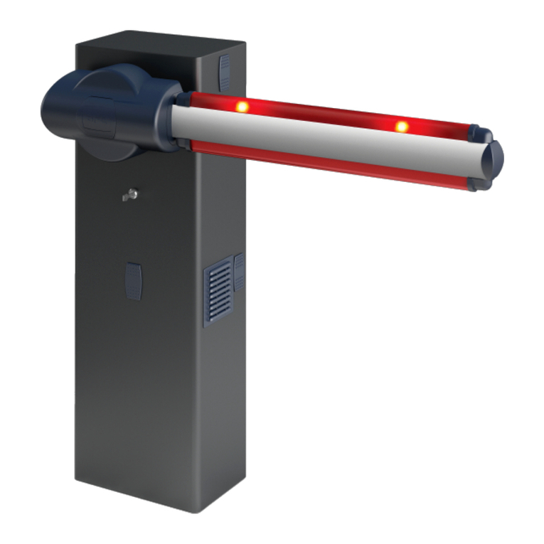
BFT XPASS B 1200C User manual

ISTRUZIONI D’USO E DI INSTALLAZIONE
INSTALLATION AND USER’S MANUAL
XPASS B 1200C
XPASS B 1200C
DISSUASORE AUTOMATICO DI SICUREZZA
AUTOMATIC SECURITY BOLLARD
Attenzione! Leggere attentamente le “Avvertenze” all’interno! Caution! Read “Warnings” inside carefully! Attention! Veuillez lire attentivement les Avertissements qui se trouvent à l’intérieur!
Achtun
g
!Bitte lesen Sie aufmerksam die„Hinweise“ im Inneren!
¡
Atención
¡
Leer atentamente las“Advertencias”en el interior! Let o
p
! Lees de“Waarschuwin
g
en”aan de binnenkant zor
g
vuldi
g
!
D812187 00550_02 27-07-16


- 3 -
Il libretto di INSTALLAZIONE USO E MANUTENZIONE è destinato agli installatori, agli utilizzatori ed agli operatori della manutenzione.
Leggere attentamente il libretto prima di installare il prodotto, utilizzarlo e prima di eseguire manutenzione ordinaria o straordinaria.
Le operazioni che possono presentare rischi se non eettuate correttamente, sono indicate con i simboli:
Il costruttore non è responsabile per danni arrecati a persone, animali o cose dovuti ad applicazioni che superano i limiti indicati nella scheda tecnica
allegata o dall’uso diverso da quello per cui il prodotto è stato progettato.
Le indicazioni precedute da questo simbolo contengono informazioni di particolare importanza, il loro mancato rispetto può comportare
la perdita della garanzia contrattuale
GENERALITÀ
Dissuasore testato e certicato (crash-tested) da Laboratorio indipendente accreditato secondo lo standard IWA14-1:2013 V/7200[N3C]/80/90, equivalente
a PAS68:2010 7500/80/N3 e ASTM2656:2007 M50.
DATI TECNICI
The INSTALLATION, USE AND MAINTENANCE handbook is for installers, users and maintenance engineers.
Please read it carefully before installing the appliance, before using it and before routine or extraordinary maintenance work.
Operations that, if not carried out correctly, can be risky, are indicated with the following symbols:
The manufacturer is not liable for injury to people or animals or damage to things in the case of applications that exceed the limits specied on the
enclosed technical data sheet or by a use dierent from what the appliance has been designed.
The notices preceded by this symbol provide important information, the non-compliance with such instructions voids the manufacturer’s
guarantee.
GENERAL
Deterrent bollard crash-tested and certied by accredited third-party Laboratory according to IWA14-1:2013 V/7200[N3C]/80/90, equivalent to PAS68:2010
7500/80/N3 and ASTM2656:2007 M50.
TECHNICAL SPECIFICATIONS
IT
EN
Alimentazione..............................................230 Vac ± 10% ; 50÷60 Hz; 1 550W
Frequenza di lavoro nominale.................................................................2 000 / 24h
Grado di protezione..................................................................................................IP67
Centrale di comando............................................PERSEO CBE (max 2 dissuasori)
Temperatura di esercizio............................................................da -40 * a+60 °C
*Con riscaldatore integrato attivo
Power............................................................230 Vac ± 10% ; 50÷60 Hz; 1 550 W
Nominal Working frequency.....................................................................2 000 / 24h
Protection level...........................................................................................................IP67
Control unit.................................................................PERSEO CBE (max 2 bollards)
Operating temperature...................................................................-40 *** to +60 °C
*** With integrated heater active
Tempo di salita (versione standard)........................................................÷ 6,3 s.**
Tempo di salita (versione con ECD) ........................................................÷ 1,5 s.**
Tempo di discesa (regolato in fabbrica, regolabile sul campo)...÷ 4,0 s.**
Peso netto............................................................................................................... 690 kg
Peso lordo............................................................................................................... 756 kg
** A temperatura ambiente +25°C
Rise time (standard version)..........................................................................÷ 6,3 s.**
Rise time (version with ECD)..........................................................................÷ 1,5 s.**
Lowering time (factory adjusted, on- eld adjustable)).......................÷ 4,0 s.**
Net weight.................................................................................................................690 kg
Gross weight............................................................................................................756 kg
** To 25 °C ambient temperature)

- 4 -
2DISPOSIZIONE • LAYOUT
A (*)
Cemento (non fornito)
Concrete (not supplied)
B
Tubo corrugato Ø125 per passaggio cablaggi
Ø125mm corrugated duct duct for cable passage
C
Allacciamento a sistema di drenaggio Ø100 (non fornito)
Ø100 hose for drainage system connection (not supplied)
D
Ghiaia (non fornito)
Pebble gravel (not supplied)
E (*)
Armatura di fondazione (non fornito)
Rebar (not supplied)
DIMENSIONI D’INGOMBRO • OVERALL SIZE DIMENSIONS
1
Tubo corrugato Ø125mm
Lungh. ~1600mm
Ø125mm corrugated duct
Length ~1600mm
Drenaggio Ø100mm
Drainage Ø100mm
Centrale oleodinamica
Hydraulic power unit
Dissuasore
Bollard
1990
1800
D
E(*)
E(*)
F(*)
B
E(*)
C
H(*)
A(*)
(*) VEDI SCHEMA FONDAZIONE (TAVOLA COD. 035985-A)
SEE FOUNDATION SCHEME (TABLE CODE 035985-A)
1980
567
615
530
567
1200
Ø330
600
500
IT EN
1014
610
625
625
RECOMMENDED
TRAFFIC DIRECTION
DIREZIONE TRAFFICO
RACCOMANDATA

- 5 -
SCHEMA DI CABLAGGIO • WIRING DIAGRAM
3
1800
min.1800
SCAVO DI FONDAZIONE • FOUNDATION EXCAVATION
4
2000
ENIT
PERSEO
CBE
3
SEZIONE CAVI / WIRING SECTION (mm²)
1
Linea Monofase - Single-phase line
2 x 1,5 + T (PE)
2
Ricevitore - Receiver 4 x 0,5
3
Rilevatore acustico di sirene - Acoustic siren detector 4 x 0,5
4Lampeggiante - Flashing light 2 x 0,5
5Selettore a chiave - Key selector 2 x 0,5
6XPASS B 1200C Cavo in dotazione da collegare / Cable supplied to be wired
7Rivelatore magnetico - Loop detector Cavo intrecciato / Twisted cable
8Fotocellula trasmettitore - Trasmitter photocell 2 x 0,5
9Fotocellula ricevitore - Receiver photocell 4 x 0,5
10 Semaforo - Trac light 3 x 0,5 + T (PE)

- 6 -
OPERAZIONI PRELIMINARI • PRELIMINARY OPERATIONS
5
Tubo HP
HP Hose
Cavo Dissuasore16P
Bollard Cable 16P
A
C
D
Tubo corrugato Ø125mm, Lungh. ~1600mm
Corrugated duct Ø125mm, Length ~1600mm
Rimuovere staa di sicurezza e angia
Remove the safety bracket and ange
Rimuovere angia e centrale oleodinamica
Remove the ange and the
hydraulic power unit
Inserire cavi nel tubo corrugato
Ø100mm
Insert cables in the corrugated duct
Ø100mm
Montare la scatola gruppo oleodinamico
Assembling box hydraulic unit
Fissaggio (non fornito)
Fastener (not supplied)
B
8mm
8mm
IT EN

- 7 -
1990
4xM16 (non forniti)
(not supplied)
E
F
INSTALLAZIONE DISSUASORE • INSTALL BOLLARD
6
Allacciamento alla rete fognaria Ø100 (non fornito)
Connection to the sewer network Ø100 (not supplied)
Ghiaia (non fornito)
Pebble gravel (not supplied)
DRENAGGIO • DRAINAGE
Assicurarsi che il terreno abbia un buon assorbimento d’acqua
immettendo circa 100 litri d’acqua e vericando che lo svuota-
mento avvenga in menodi 30 minuti;in casocontrario realizzareil
drenaggio delle acque tramite tubazioni da collegare ad ogni sin-
gola cassaforma e raccordate alla rete fognaria con sifone, oppure
ad un pozzetto dotato di un sistema di svuotamento dell’acqua.
Ensure that the soil has a adeguate water by about 100 liters of water
and checking that the pit empties in less than 30 minutes; otherwise
it is mandatory to realize a drainage of water through ducts con-
nected to every single manhole and linked to the sewage network
with siphon, or a collecting sump with a drainage system of water.
Tubo corrugato Ø125
Corrugated duct Ø125
Tubo HP
HP Hose
Cavo Dissuasore 16P
Bollard Cable 16P
Fissare tubo corrugato al dissuasore e alla scatola gruppo oleodinamico
Fix the
corrugated duct to bollard and the
box hydraulic unit
Avvitare i golfari
Screw the eyebolts
Tubo corrugato Ø50 (non fornito)
Corrugated duct Ø50 (not supplied)
Fissaggio
(non fornito)
Fastener
(not supplied)
Fissaggio (non fornito)
Fastener (not supplied)
ENIT
Cavo PERSEO CBE 17p
PERSEO CBE Cable 17p

- 8 -
IT EN
RECOMMENDED
TRAFFIC DIRECTION
DIREZIONE TRAFFICO
RACCOMANDATA
Alla centrale di comando PERSEO CBE
(vedi par. 14)
To PERSEO CBE control unit
(see chapter 14)
non fornita
not supplied
Drenaggio Ø100 (non fornito)
Drenaige Ø100 (not supplied)
Tubo corrugato Ø50 (non fornito)
Corrugated duct Ø50 (not supplied)
Tubo corrugato Ø50 (non fornito)
Corrugated duct Ø50 (not supplied)

- 9 -
LIVELLARE COL PIANO STRADALE • LEVEL WITH THE ROAD SURFACE
7
COMPLETARE LA PAVIMENTAZIONE • FINISH THE FLOORING
RIEMPIRE DI CEMENTO • FILL WITH CONCRETE
9
8
Per evitare che il cemento chiuda le sedi
delleviti,assicurarsichelevitiM10x25siano
montate al dissuasore prima di gettare il
cemento.
To avoid concrete spillage into screw
threads, assure that M10x25 screws are
assembled on the ange support plate
before pouring the concrete.
ENIT

- 10 -
1 2 3 4 5 6 7 8 9 10 11 12 13 14 15 16 17
CAVO MOTORE 4P
MOTOR CABLE 4P
brown/green
yellow
purple
green
brown + gray
blue + black
white
red
gray/pink
+ red/blue
brown
gray
black
brown
blue
yellow/green
pink
CAVO CENTR. OLEODINAMICA 16P
HYDRAULIC POWER CABLE 16P
Cablaggio di fabbrica
Factory wiring
TOGLIERE I GOLFARI, LE VITI E REINSTALLARE POMPA OLEODINAMICA • REMOVE THE EYEBOLTS, THE SCREWS AND REINSTALL THE
HYDRAULIC PUMP
SCHEMA CAVI CABLATI NELLA SCATOLA DI DERIVAZIONE • WIRING INSIDE CONNECTION BOX
10
11
AB
IT EN
Tubo HP
HP Hose
Scatola di derivazione
Connection box
Innestare Tubo HP
Insert HP Hose
Cavo motore
Motor cable
Cavo Centrale oleodinamica
Hydraulic power cable

- 11 -
COLLEGAMENTI CAVO DISSUASORE • BOLLARD CABLE CONNECTIONS
12
13
1 2 3 4 5 6 7 8 9 10 11 12 13 14 15 16 17
pink/white
yellow/white
orange/white
green/white
black/white
yellow
orange
green
white
yellow/green
blue + gray
red/white
red
pink
1 2 3 4 5 6 7 8 9 10 11 12 13 14 15 16 17
purple
green
white
brown + gray
blue + black
yellow or red (*)
pink
gray/pink + red/blue
white/yellow
+ yellow/brown
Aprire scatola di derivazione e connettere
il cavo dissuasore 16P.
To open to derivation box and to connect
the bollard cable 16P.
Chiudere la scatola di derivazione dopo il cablaggio
Close the derivation box after wiring
Isolare i cavi non utilizzati
Insulate unused wires
Isolare i cavi non utilizzati
Insulate unused cable
ENIT
Cavo PERSEO CBE
PERSEO CBE cable
Connettere il
cavo PERSEO CBE 17p
Connect the
PERSEO CBE Cable 17p
COLLEGAMENTI CAVO CENTRALE DI COMANDO PERSEO CBE • PERSEO CBE POWER UNIT CABLE CONNECTIONS
(*) Collegare il cavo rosso per luci rosse
o il cavo giallo per luci ambra
(*) Connect the red wire for red lights or
the yellow wire for amber lights
Cavo Dissuasore
Bollard cable

- 12 -
MONTARE LE FLANGE • ASSEMBLE THE FLANGES
M10x25 8mm
MOTB
COM
EV1
EV2
GND
gary+blue
yellow/green
brown+black
pink/white
red/white
yellow
pink
yellow/white
red
orange
green
orange/white
black/white
green/white
white
PRESS
1
COM
PRESS
2
AUX
PDM
FCA
FCC
OUT
LED
OUT
BUZZER
BRK +
J3 J5J4
COLLEGAMENTI ELETTRICI ALLA CENTRALE DI COMANDO • ELECTRICAL CONNECTIONS TO CONTROL UNIT
14
15
Isolare i cavi non utilizzati
Insulate unused cable
IT EN
PERSEO CBE
Consultare il manuale d’installazione e uso della centralina PERSEO CBE.
Consult the PERSEO CBE control unit’s installation and operating manual.

- 13 -
SICUREZZA GENERALE
• Si consiglia, per ragioni di sicurezza e nel rispetto delle normative vigenti, di utilizzare l’apposita centralina di comando.
• Gli elementi costruttivi della macchina devono essere in accordo con le seguenti Direttive Europee:2014/30/CEE (direttiva compatibilità elettromagnetica),
2006/42/CEE (direttiva macchine), 2014/35/CEE (direttiva bassa tensione) e loro modiche successive. Per tutti i Paesi extra CEE, oltre alle norme nazionali
vigenti, per un buon livello di sicurezza è opportuno rispettare anche le norme sopracitate.
• La Ditta declina qualsiasi responsabilità dall’inosservanza della Buona Tecnica nella installazione del dispositivo descritto nel presente manuale.
• Non installare il prodotto in atmosfera potenzialmente esplosiva o in presenza di rischio di incendio.
• Togliere l’alimentazione elettrica, prima di qualsiasi intervento sull’impianto. Scollegare anche eventuali batterie tampone se presenti.
• Prevederesullarete dialimentazionedell’automazione,uninterruttoreoun magnetotermicoonnipolarecon distanzadiapertura deicontattiugualeo superiore
a 3,5 mm. Prevedere un dispositivo di sezionamento adeguato anche per le batterie tampone.
• Vericare che a monte della rete di alimentazione, vi sia un interruttore dierenziale con soglia da 0.03A.
• Vericare se l’impianto di terra è realizzato correttamente.
• L’installazione deve essere fatta utilizzando dispositivi di sicurezza e comandi conformi alla EN 12978.
• Applicare tutti i dispositivi di sicurezza (fotocellule, coste sensibili, ecc.) necessari a proteggere l’area da pericoli di schiacciamento, convogliamento.
• Applicare almeno un dispositivo di segnalazione luminosa (lampeggiante) in posizione visibile in modo visibile e vicino alla struttura un cartello di avviso.
• Usareesclusivamentepartioriginaliperqualsiasimanutenzioneoriparazione.LaDittadeclinaogniresponsabilitàainidellasicurezzaedelbuonfunzionamento
dell’automazione se vengono impiegati componenti di altri produttori.
• Non eseguire alcuna modica ai componenti dell’automazione se non espressamente autorizzata dalla Ditta.
• Smaltire i materiali di imballo (plastica, cartone, polistirolo, ecc.) secondo quanto previsto dalle norme vigenti. Non lasciare buste di nylon e polistirolo a portata
dei bambini.
• Tutto ciò che non è espressamente previsto in queste istruzioni, non è permesso.
• Istruire l’utilizzatore dell’impianto su quanto riguarda i sistemi di comando applicati e sull’esecuzione dell’apertura manuale in caso di emergenza.
• Non permettere a persone e bambini di sostare nell’area d’azione dell’automazione.
• Non lasciare radiocomandi o altri dispositivi di comando alla portata dei bambini onde evitare azionamenti involontari dell’automazione.
USO
• Consultare il manuale d’installazione e uso della centralina.
MANUTENZIONE ORDINARIA
(OGNI SEI MESI)
• La manutenzione deve essere eseguita solo da personale qualicato.
• Controllare visivamente lo stato generale di conservazione delle parti esterne
del dissuasore.
• Controllare che la pellicola retroriettente dello stelo non sia usurata.
• Controllare la funzionalità delle luci.
• Controllare il funzionamento della manovra di emergenza.
• Controllare il funzionamento della centralina e dei dispositivi di sicurezza.
GENERAL SAFETY
• For safety reasons and to comply with current standards, we recommend using the control unit.
• The construction components of this product must comply with the following European Directives: 2014/30/EEC (Electromagnetic Compatibility), 2006/42/
EEC(MachineryDirective),2014/35/EEC(LowVoltageDirective)andsubsequentamendments.Asforallnon-EECcountries,theabove-mentionedstandards
as well as the current national standards should be respected in order to achieve a good safety level.
• The Company declines all responsibility for any consequences resulting from failure to observe Good Technical Practice when installing the device described
in the present manual.
• Do not install the product in potentially explosive atmosphere or wherever there is a re risk.
• Disconnect the electrical supply before carrying out any work on the installation. Also disconnect any buer batteries, if tted.
• Fit an omnipolar or magnetothermal switch on the mains power supply, having a contact opening distance equal to or greater than 3,5 mm. Also t an adequate
cut-out device for the buer batteries.
• Check that a dierential switch with a 0.03A threshold is tted just before the power supply mains.
• Check that earthing is carried out correctly.
• Installation must be carried out using the safety devices and controls prescribed by the EN 12978 Standard.
• Fit all the safety devices (photocells, electric edges etc.) which are needed to protect the area from any danger caused by squashing, conveying.
• Position at least one luminous signal indication device (blinker) where it can be easily seen, and x a Warning sign next to the structure.
• Only use original parts for any maintenance or repair operation. The Company declines all responsibility with respect to the automation safety and correct
operation when other producers’components are used.
• Do not modify the automation components, unless explicitly authorised by the Company.
• Scrap packing materials (plastic, cardboard, polystyrene etc) according to the provisions set out by current standards. Keep nylon or polystyrene bags out of
children’s reach.
• Anything which is not expressly supplied for in the present instructions, is not allowed.
• Instruct the product user about the control systems supplied and the manual opening operation in case of emergency.
• Do not allow persons or children to remain within the automation operation area.
• Keep radio control or other control devices out of children’s reach, in order to avoid unintentional automation activation.
USE
• Consult the control unit’s installation and operating manual.
ROUTINE MAINTENANCE
(EVERY 6 MONTHS)
• Maintenance must be carried out by qualied personnel only.
• Visually check the overall state of wear and tear of the external parts of the
deterrent bollard.
• Make sure the rear-reecting lm is not worn.
• Make sure the lights work.
• Make sure the emergency manoeuvre is working properly.
• Make sure the control unit and safety devices are in proper working order.
IT
EN

- 14 -

- 15 -
Dati impianto • Installation data
Installatore
Installer
Cliente
Customer
Matricola
Serial number
Data installazione
Installation date
Data attivazione
Activation date
Luogo
Location
Nr. Data • Date Descrizione intervento • Intervention description Firma •Signature
1
Tecnico • Technician
Cliente • Customer
2
Tecnico • Technician
Cliente • Customer
3
Tecnico • Technician
Cliente • Customer
4
Tecnico • Technician
Cliente • Customer
5
Tecnico • Technician
Cliente • Customer
6
Tecnico • Technician
Cliente • Customer
7
Tecnico • Technician
Cliente • Customer
8
Tecnico • Technician
Cliente • Customer
9
Tecnico • Technician
Cliente • Customer
REGISTRO DI MANUTENZIONE
MAINTENANCE LOG

INSTALLATORE
INSTALLER
ITALY
Other manuals for XPASS B 1200C
3
Table of contents
Other BFT Security System manuals