BG Trade BGT-Link-A3G User manual

Model Name BGT-Link-A3G
Latest Firmware Date 2014 - 07 - 09
Manual Version Rev. 2.5
Language English
Instruction Manual
High-Definition Link for Audi
BGT-Link-A3G

Contents
•Cautions
•Dimension & Exterior
•Components & Optional parts
•Full Installation Diagram
•CAN wires information(exceptions)
•HDMI Connection Diagram
•Navigation Connection Diagram(TypeA & B)
•Compatibility Chart for Navigation(GPS) box models
•LVDS Connection Diagram
•Body Connector specifications
•Car Compatibility Chart
•Activation by original buttons of Audi
•DIP Switch Settings
•Settings
1. Enter into the setting menu
2. HDMI mode settings
3. NAVI mode settings
4. Rear view camera settings
5. AV1(Front view camera) settings
6. Automatic activation function(AV1)
7. AV2 settings
8. System settings
9. System information
10. Information of Dip switch settings
_____________________________________________________________ 3
_________________________________________________ 4
_________________________________________ 5
______________________________________________ 6
____________________________________ 7
____________________________________________ 8
___________________________ 9
___________________ 10
___________________________________________ 11
_______________________________________ 12
______________________________________________ 13
_________________________________ 14
_________________________________________________ 15
____________________________________ 16
___________________________________________ 17
____________________________________________ 17
_____________________________________ 18
________________________________ 18
_____________________________ 19
__________________________________________________ 19
_______________________________________________ 20
____________________________________________ 20
______________________________ 21

3
BGT-Link-A3G - related
•You should check the names and colors of each wires exactly, before you connect the wires.
ex) CAN HIGH: White wires / CAN LOW: Blue wires
• The ‘POWER / CAN Cable’ should always be connected last and be disconnected first.
•The 'Mode Switch' is an optional part to change modes forcibly without CAN-BUS.
Generally, the CAN-BUS wires are connected for changing modes by original buttons.
•When the reverse gear is not detected by CAN-BUS,
the 'REVERSE 12V IN wire’ should be spliced with 12V power of reverse light.
HDMI device-related
•HDMI mode accepts general-screen resolution of HDMI devices.
If screen size of HDMI does not fit on the monitor, should adjust screen size & position in 'settings mode'.
•Generally, '5V 1A Power output(5V USB POWER)' is a standard voltage for charging smartphone.
If you need higher voltage than 5V, you should add a separate power supply.
Navigation(GPS) box-related
•When you connect the power wires(B+, ACC) to the navigation(GPS) box,
the ‘NAVI 12V OUT' wire supported by IW04Ashould be spliced with anACC wire of navigation box.
•After installation is done, select an applicable navigation(GPS) box model in the 'Navigation model selection
menu' of setting mode.
•The navigation box should be powered off before unplugging the HDMI cable.
Cautions
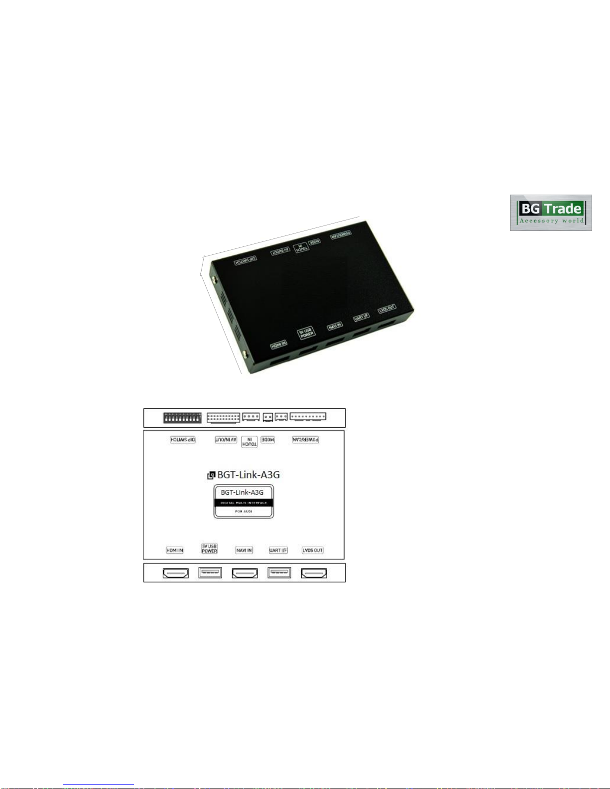
Exterior
Dimension
4
ⓐ
DIP SWITCH
ⓑ
AV IN / OUT
ⓒ
TOUCH IN
ⓓ
MODE
ⓔ
POWER / CAN
ⓕ
HDMI IN
ⓖ
5V USB POWER
ⓗ
NAVI IN
ⓘ
UART I/F
ⓙ
LVDS OUT
ⓐⓑⓒⓓⓔ
ⓕⓖⓗⓘⓙ
Width: 142 mm
Length: 91 mm
Height: 22 mm
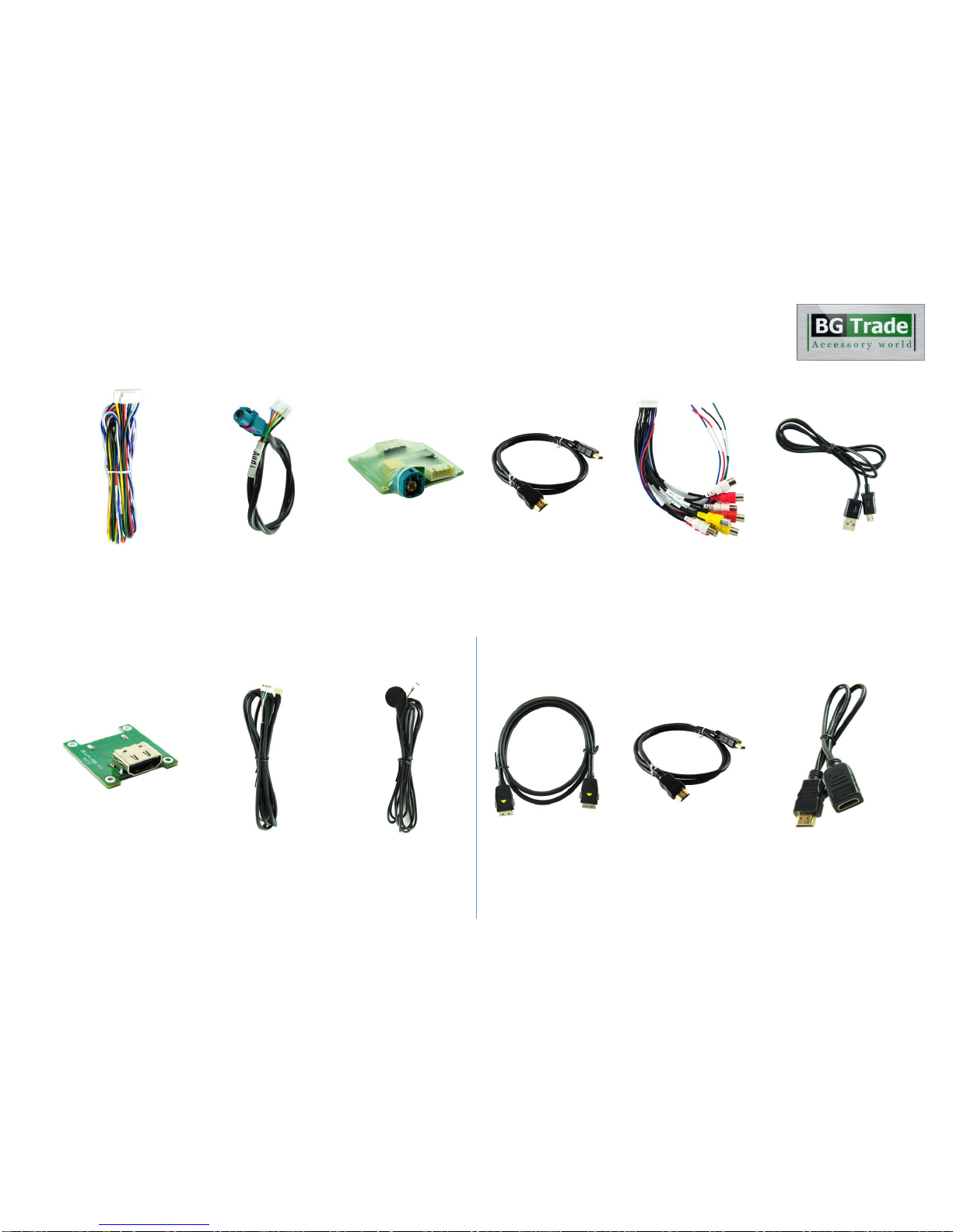
Components
5
Optional Parts(sold separately at the KAP)
TTA 24-Pin to HDMI Gender
(For iNAVI CUBE)
Optional Parts(purchased separately)
HDMI extender
(For stick type HDMI device)
iNAVI CUBE LCD Cable HDMI Cable
(Male to Male)
Touch-IN Cable Mode Switch
Power / CAN Cable LVDS Cable LVDS PCB HDMI Cable AV IN / OUT Cable 5-pin Micro USB Cable
Table of contents
Popular Automobile Accessories manuals by other brands


ULTIMATE SPEED
ULTIMATE SPEED 279746 Assembly and Safety Advice

SSV Works
SSV Works DF-F65 manual

ULTIMATE SPEED
ULTIMATE SPEED CARBON Assembly and Safety Advice

Witter
Witter F174 Fitting instructions

WeatherTech
WeatherTech No-Drill installation instructions

TAUBENREUTHER
TAUBENREUTHER 1-336050 Installation instruction