BGS technic 62630 User manual
BGS technic KG
Bandwirkerstr. 3
42929 Wermelskirchen
Tel.: 02196 720480
Fax.: 02196 7204820
mail@bgs-technic.de
www.bgstechnic.com
© BGS technic KG, Vervielfältigung und Weiterverwendung verboten
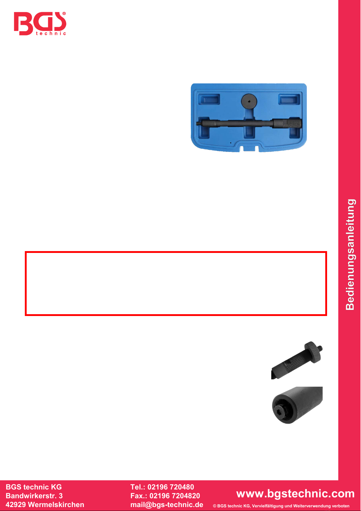
Art. 62630
Injektor-Dichtring-Auszieher
WERKZEUGE
1Rändelmutter
2 Spreizgreifer
3 Injektor-Dichtring-Auszieher
VERWENDUNGSZWECK
Dieses Werkzeug wurde speziell für die Demontage der Kupferdichtringe im Zylinderkopf entwickelt.
Oft befinden sich diese Dichtringe sehr tief am Boden des Injektor-Schachts, was eine Demontage nach
herkömmlicher Art nahezu unmöglich macht. Das Werkzeug wurde sehr schlank, mit einem an der Spitze
angebrachten Spreizgreifer konstruiert und ermöglicht in Verbindung mit einem Gleithammer eine leichte
Demontage auch festsitzender Injektor-Dichtringe.
SICHERHEITSHINWEISE
•Verwenden Sie das Werkzeug nur für die unter „Verwendungszweck“ angegebene Arbeit.
•Überprüfen Sie vor der Benutzung das Werkzeug auf Beschädigung, verwenden Sie das Werkzeug
nicht, wenn es beschädigt ist.
•Lassen Sie keine Kinder mit dem Werkzeug oder dessen Verpackung spielen.
•Legen Sie das Werkzeug niemals auf die Fahrzeug-Batterie. Gefahr von Kurzschluss.
•Halten Sie Kinder und andere unbefugte Personen vom Arbeitsbereich fern.
•Entfernen Sie vor der Reparatur den Zündschlüssel, so verhindern Sie ein versehentliches Starten
des Motors.
WERKZEUGEINSTELLUNG
1. Stellen Sie die Tiefe des Spreizgreifers vor der Montage des
Werkzeugs ein, demontieren Sie dazu die Rändelmutter (1).
2. Stellen Sie jetzt die Tiefe durch Drehen des Spreizgreifers (2) im oder
gegen den Uhrzeigersinn ein.
3. Die Tiefe muss in etwa der Stärke des Dichtrings entsprechen bzw. der
Bund des Spreizgreifers muss nach dem Spannen hinter den Dichtring
greifen.
4. Die Rändelmutter, vor dem Einsetzen des Werkzeugs in den Injektor-
Schacht, mehrere Gewinde auf das Gewinde drehen.
1
2
1
3
2
BGS technic KG
Bandwirkerstr. 3
42929 Wermelskirchen
Tel.: 02196 720480
Fax.: 02196 7204820
mail@bgs-technic.de
www.bgstechnic.com
© BGS technic KG, Vervielfältigung und Weiterverwendung verboten
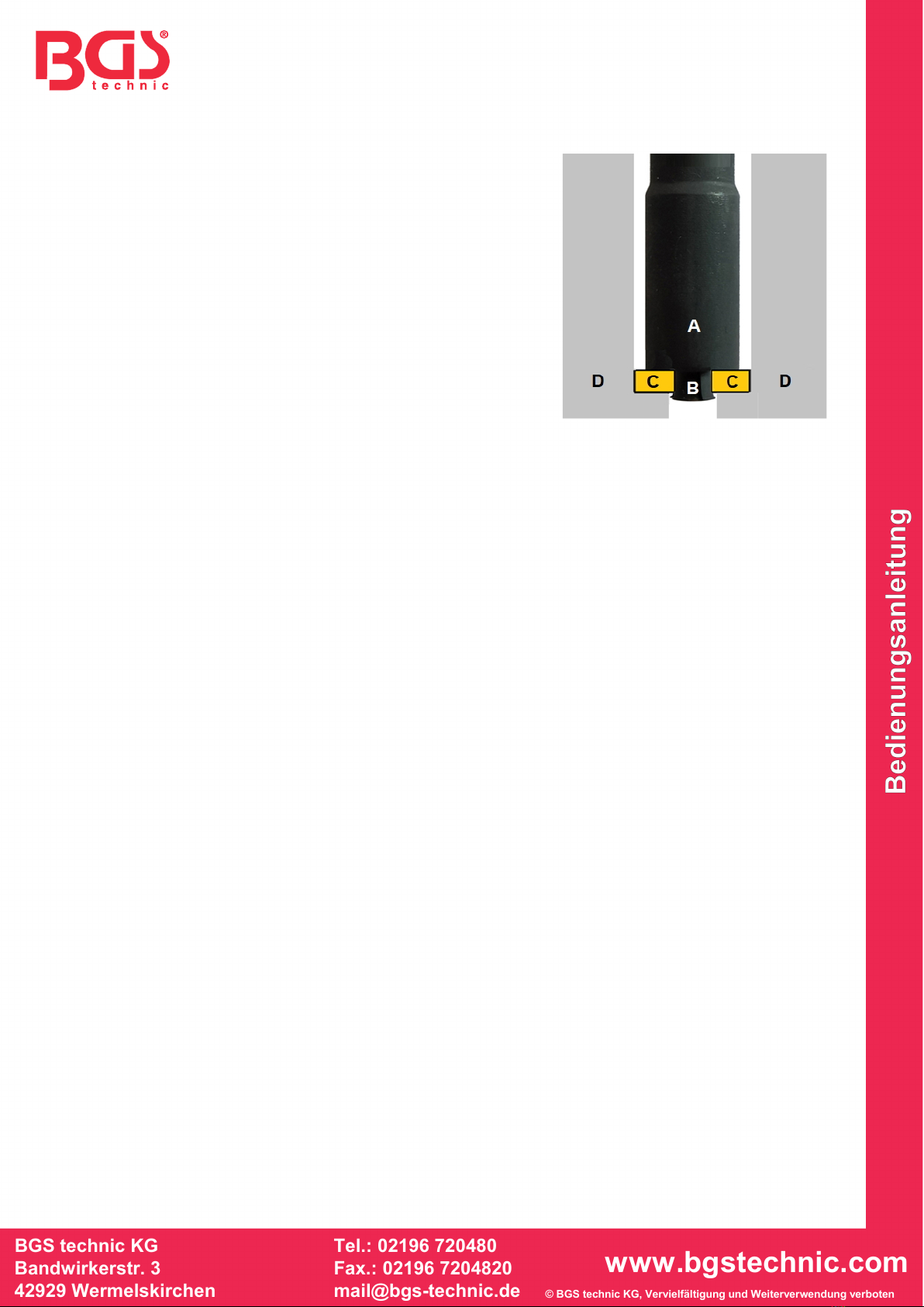
WERKZEUGMONTAGE
AInjektor-Dichtring-Auszieher
BSpreizgreifer
CInjektor-Dichtring
DZylinderkopf
5. Entfernen zunächst Sie den Injektor und reinigen Sie den
Injektor-Schacht. Beachten Sie dabei, dass keine
Verunreinigung in den Zylinder fällt.
6. Führen Sie das Werkzeug in den Injektor-Schacht ein.
7. Drehen Sie die Rändelmutter im Uhrzeigersinn, bis der
Spreizgreifer (B) in der Dichtringbohrung greift.
8. Ziehen Sie am Werkzeug um den Dichtring herauszuziehen.
9. Sollte sich der Dichtring von Hand nicht herausziehen lassen,
kann ein geeigneter Gleithammer an das obere Gewinde der
Rändelschraube (M10x1.5), zur Demontage des Dichtrings,
montiert werden.

BGS technic KG
Bandwirkerstr. 3
D-42929 Wermelskirchen
Tel.: 02196 720480
Fax.: 02196 7204820
mail@bgs-technic.de
www.bgstechnic.com
© BGS technic KG, Copying and further use not allowed
62630
Injector Gasket Puller
TOOLS
1 Knurled Nut
2 Spreader
3 Injector Gasket Puller
INTENDED USE
This tool has been specially developed for extracting copper sealing washers in the cylinder head.
These sealing washers are often located very deep at the bottom of the injector shaft, which makes
conventional removal virtually impossible. The tool has a very thin design with a spreader attached to the
tip and enables easy removal in conjunction with a sliding hammer of tight-fitting injector sealing washers.
SAFETY INFORMATION
•Use the tool only for work that is specified under Intended Use.
•Inspect the tool for damage before using. Do not use the tool if it is damaged.
•Do not let any children play with the tool or its packaging.
•Never place the tool on the vehicle battery. Danger of short circuit!
•Keep children and other unauthorised persons away from the work area.
•If you remove the ignition key before repairing, you can prevent the engine from being started
accidentally.
TOOL SETTING
1. Set the depth of the spreader before assembling the tool. To do this,
remove the knurled nut (1).
2. Now set the depth of the spreader (2) clockwise or counter-clockwise.
3. The depth must approximately correspond to the thickness of the
sealing ring or the collar of the spreader must grip behind the sealing
ring after tightening.
4. Before inserting the tool into the injector shaft, turn the knurled nut
several screw threads on the thread.
1
3
2
2
1

BGS technic KG
Bandwirkerstr. 3
D-42929 Wermelskirchen
Tel.: 02196 720480
Fax.: 02196 7204820
mail@bgs-technic.de
www.bgstechnic.com
© BGS technic KG, Copying and further use not allowed
TOOL ASSEMBLY
AInjector gasket puller
BSpreader
CInjector sealing washer
DCylinder head
5. First remove the injector and clean the injector shaft. Make
sure that no dirt falls into the cylinder.
6. Insert the tool into the injector shaft.
7. Turn the knurled nut clockwise until the spreader (B) grips in
the sealing washer hole.
8. Pull on the tool to pull out the sealing washing.
9. If the sealing washer cannot be pulled out by hand, a suitable
sliding hammer can be mounted on the top thread of the
knurled screw (M10x1.5) to remove the sealing ring.

BGS technic KG
Bandwirkerstr. 3
D-42929 Wermelskirchen
Tel.: 02196 720480
Fax.: 02196 7204820
mail@bgs-technic.de
www.bgstechnic.com
62630
Extracteur de joints d’injecteur
OUTILS
1 L’écrou moleté
2 Pince d'expansion
3 Extracteur
de joints d’injecteur
UTILISATION PRÉVUE
Cet outil a été spécialement développé pour le démontage des bagues d’étanchéité en cuivre dans la
culasse.
Ces bagues d’étanchéité sont souvent situées très profondément au fond de l’alésage de l’injecteur, ce qui
rend presque impossible le démontage de manière conventionnelle. L’outil est très fin, avec une pince
d’expansion située à l’extrémité et permet, en conjonction avec une masse à inertie, le démontage facile
des bagues d’étanchéité d’injecteurs, même fortement bloquées.
CONSIGNES DE SÉCURITÉ
•N’utilisez l’outil que pour les tâches indiquées sous le point « Utilisation conforme ».
•Vérifiez l’outil avant son utilisation et ne l’utilisez pas s’il est endommagé.
•Ne permettez jamais que des enfants jouent avec l’outil ou avec son emballage.
•Ne posez jamais l’outil sur la batterie du véhicule. Risque de court-circuit.
•Maintenez à l’écart les enfants et toutes les autres personnes non autorisées de la zone de travail.
•Retirez la clé de contact avant de commencer le travail ; vous évitez ainsi de démarrer le moteur par
inadvertance.
RÉGLAGE DE L’OUTIL
1. Réglez la profondeur de la pince d’expansion avant de monter l’outil en
retirant l’écrou moleté (1).
2. Maintenant, réglez la profondeur en tournant la pince d’expansion (2)
dans le sens des aiguilles d’une montre ou dans le sens inverse des
aiguilles d’une montre.
3. La profondeur doit correspondre approximativement à l’épaisseur de la
bague d’étanchéité ou le collier de la pince d’expansion doit s’accrocher
derrière la bague d’étanchéité après le serrage.
4. Avant d’insérer l’outil dans l’alésage de l’injecteur, tournez l’écrou
moleté plusieurs tours sur le filetage.
1
2
1
3
2
BGS technic KG
Bandwirkerstr. 3
D-42929 Wermelskirchen
Tel.: 02196 720480
Fax.: 02196 7204820
mail@bgs-technic.de
www.bgstechnic.com
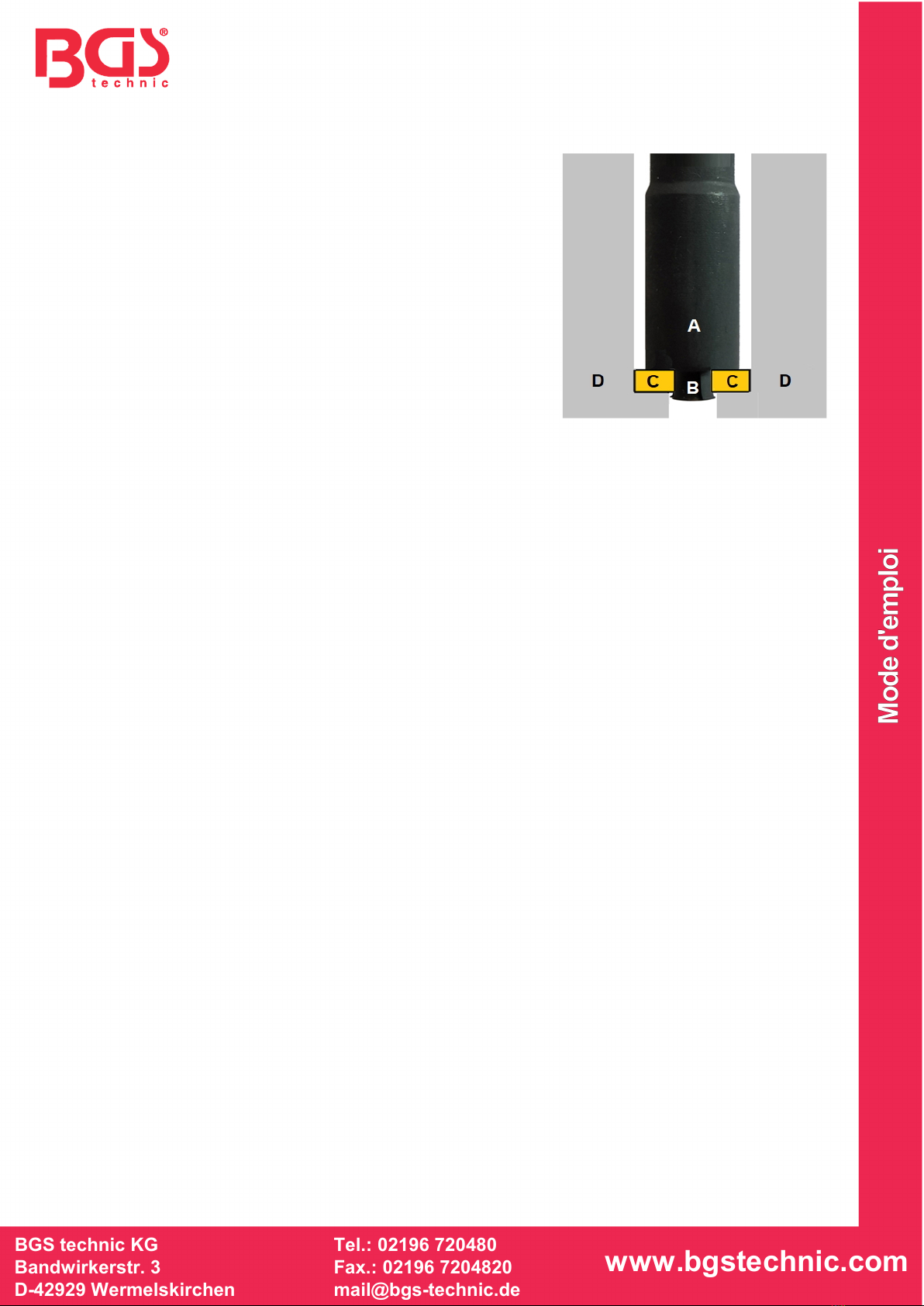
MONTAGE DE L’OUTIL
A
Extracteur de joints d’injecteur
BPince d’expansion
CBague d’étanchéité de l’injecteur
DCulasse
5. Retirez d’abord l’injecteur et nettoyez l’alésage de l’injecteur.
Veillez à ce qu’aucune contamination ne tombe dans le
cylindre.
6. Insérez l’outil dans l’alésage de l’injecteur.
7. Tournez l’écrou moleté dans le sens des aiguilles d’une
montre jusqu’à ce que la pince d’expansion (B) s’engage
dans l’alésage de la bague d’étanchéité.
8. Tirez sur l’outil pour retirer la bague d’étanchéité.
9. Si la bague d’étanchéité ne peut pas être enlevée à la main,
une masse à inertie appropriée peut être montée sur le
filetage supérieur de la vis moletée (M10x1,5) pour retirer la
bague d’étanchéité.

SW-Stahl und Werkzeugvertriebs GmbH Tel. +49 (0) 2191 / 46438-0
F5 6 e s s a r t S r e s u k r e v e Lax +49 (0) 2191 / 46438-40
e d . l h a t s w s @ o f n i : l i
a M - E
d i e h c s m e R 7 9 8 2 4 - D
Manual de Instrucciones
BGS technic KG
Bandwirkerstr. 3
D-42929 Wermelskirchen
Tel.: 02196 720480
Fax.: 02196 7204820
www.bgstechnic.com
© BGS technic KG, Copying and further use not allowed
62630
Extractor del anillo de sellado de inyectores
HERRAMIENTAS
1 Tuerca moleteada
2 Pinza de extension
3 Extractor del anillo de sellado
de inyectores
USO PREVISTO
Esta herramienta ha sido especialmente desarrollada para el desmontaje de los anillos de sellado de
cobre de la culata.
A menudo, estos anillos de sellado se encuentran a una profundidad muy grande en la parte inferior del
eje del inyector, lo que hace que el desmontaje sea casi imposible de la manera convencional. La
herramienta ha sido diseñada de forma muy delgada, con una pinza de expansión colocada en la punta y,
junto con un martillo deslizante permite un fácil desmontaje, incluso de los anillos de sellado del inyector
atascados.
INDICACIONES DE SEGURIDAD
•Utilice la herramienta solamente para los trabajos indicados en "Uso previsto».
•Verifique la herramienta antes de usarla y no la use si está dañada.
•No permita que los niños jueguen con la herramienta o su embalaje.
•Nunca deposite la herramienta sobre la batería del vehículo. Peligro de cortocircuito.
•Mantenga a los niños y otras personas no autorizadas lejos del área de trabajo.
•Retire la llave de encendido antes de la reparación, así evitará un arranque accidental del motor.
AJUSTE DE LA HERRAMIENTA
1. Ajuste la profundidad de la pinza de extensión antes de montar la
herramienta, para ello desmonte la tuerca moleteada (1).
2. Ahora ajuste la profundidad girando la pinza de extensión (2) en
sentido horario o antihorario.
3. La profundidad debe corresponder aproximadamente al grosor del
anillo de sellado o el collarín de la pinza de extensión debe alcanzar
detrás del anillo de sellado después del apriete.
4. Girar la tuerca moleteada, antes de insertar la herramienta en el eje del
inyector, varios hilos en la rosca.
1
2
1
3
2
SW-Stahl und Werkzeugvertriebs GmbH Tel. +49 (0) 2191 / 46438-0
F5 6 e s s a r t S r e s u k r e v e Lax +49 (0) 2191 / 46438-40
e d . l h a t s w s @ o f n i : l i a M - Ed i e h c s m e R 7 9 8 2 4 - D
Manual de Instrucciones
BGS technic KG
Bandwirkerstr. 3
D-42929 Wermelskirchen
Tel.: 02196 720480
Fax.: 02196 7204820
www.bgstechnic.com
© BGS technic KG, Copying and further use not allowed
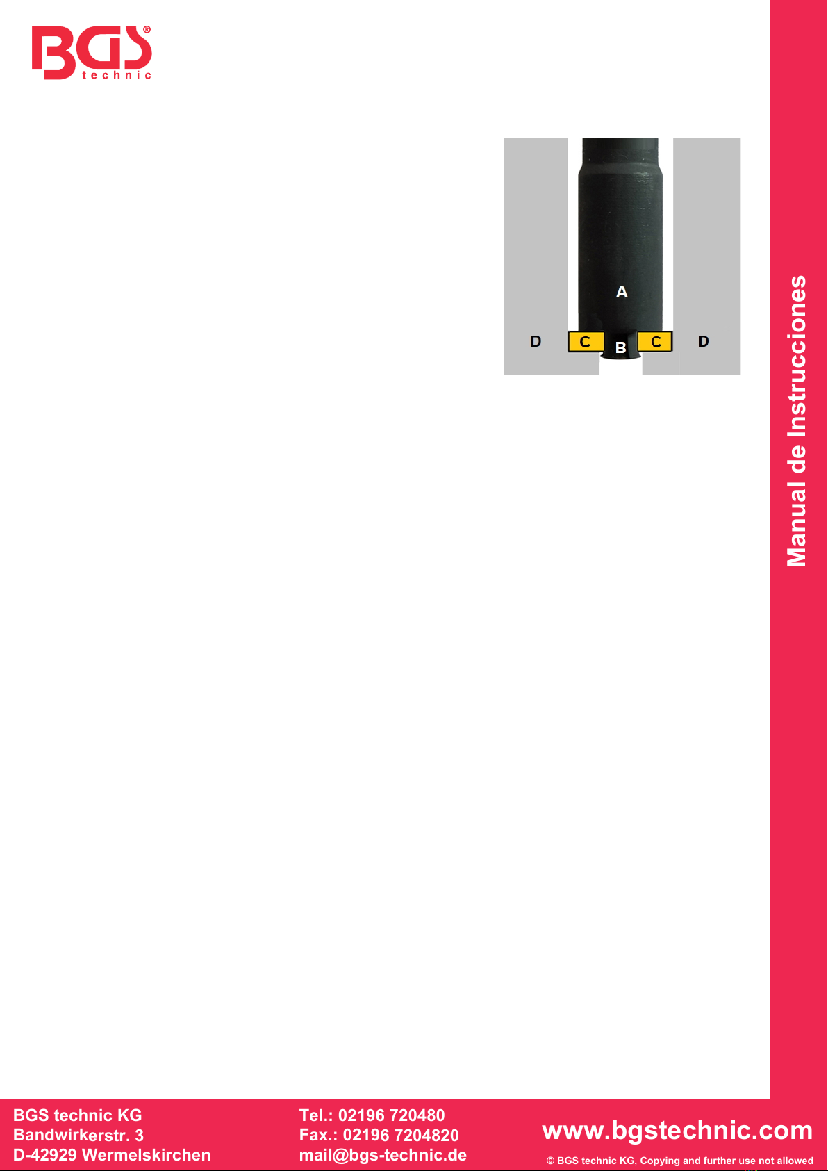
MONTAJE DE LA HERRAMIENTA
AExtractor del anillo de sellado de inyectores
BPinza de expansión
CAnillo de sellado del inyector
DCulata
5. Primero quite el inyector y limpie el eje del inyector.
Asegúrese de que no entre ninguna suciedad en el cilindro.
6. Inserte la herramienta en el eje del inyector.
7. Gire la tuerca moleteada en el sentido de las agujas del reloj
hasta que la pinza de extensión (B) agarre en el orificio del
anillo de sellado.
8. Tire de la herramienta para extraer el anillo de sellado.
9. Si el anillo de sellado no se puede extraer manualmente, se
puede montar un martillo deslizante adecuado en la rosca
superior del tornillo moleteado (M10x1.5), para desmontar el
anillo de sellado.
Table of contents
Languages:
Popular Laboratory Equipment manuals by other brands

HTL
HTL Discovery Pro quick start guide

PureAiro
PureAiro GUARDIAN 155 Installation & operation manual

SPEX CertiPrep
SPEX CertiPrep PIPWASH-1 Operation manual

PASCO
PASCO ME-6810A Product guide

Nippon Genetics
Nippon Genetics FastGene Vortexer Mini manual

Four E's Scientific
Four E's Scientific Overstar60 quick start guide

Lafayette Instrument
Lafayette Instrument CAMPDEN 7000smz instruction manual

PSI
PSI AlgaeTron Manual and user guide

Flinn Scientific
Flinn Scientific AP8503 owner's manual

Genevac
Genevac Rocket 4D user guide

Savant
Savant DNA120 instruction manual

cytiva
cytiva Sterile Tube Fuser - Wet operating instructions


