SW-Stahl und Werkzeugvertriebs GmbH Tel. +49 (0) 2191 / 46438-0
F56essartSresukreveL ax +49 (0) 2191 / 46438-40
ed.lhatsws@ofni:liaM-EdiehcsmeR79824-D
Instruction Manual
BGS technic KG
Bandwirkerstr. 3
42929 Wermelskirchen
Tel.: 02196 720480
Fax.: 02196 7204820
www.bgstechnic.com
© BGS technic KG, Copying and further use not allowed
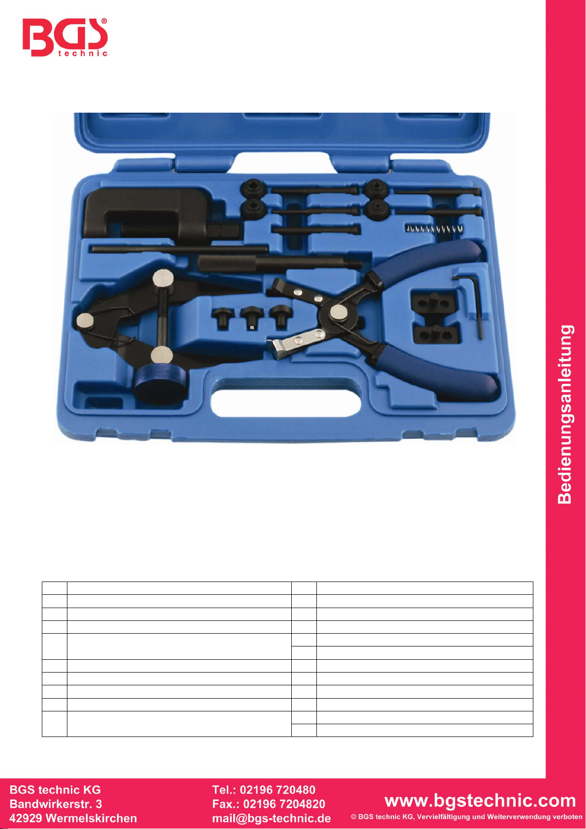
Art. 8867
Motorcycle Chain Tool Set
GENERAL INFORMATION
This tool kit includes following 3 chain service tools:
1. A pair of chain link clip removal pliers (R) that make removing and fitting the spring clips used on
some smaller chains an easy job,
2. A chain stretch tool (Q) that acts as a second pair of hands and holds the two ends of the chain
together whilst the operator assembles the new split link
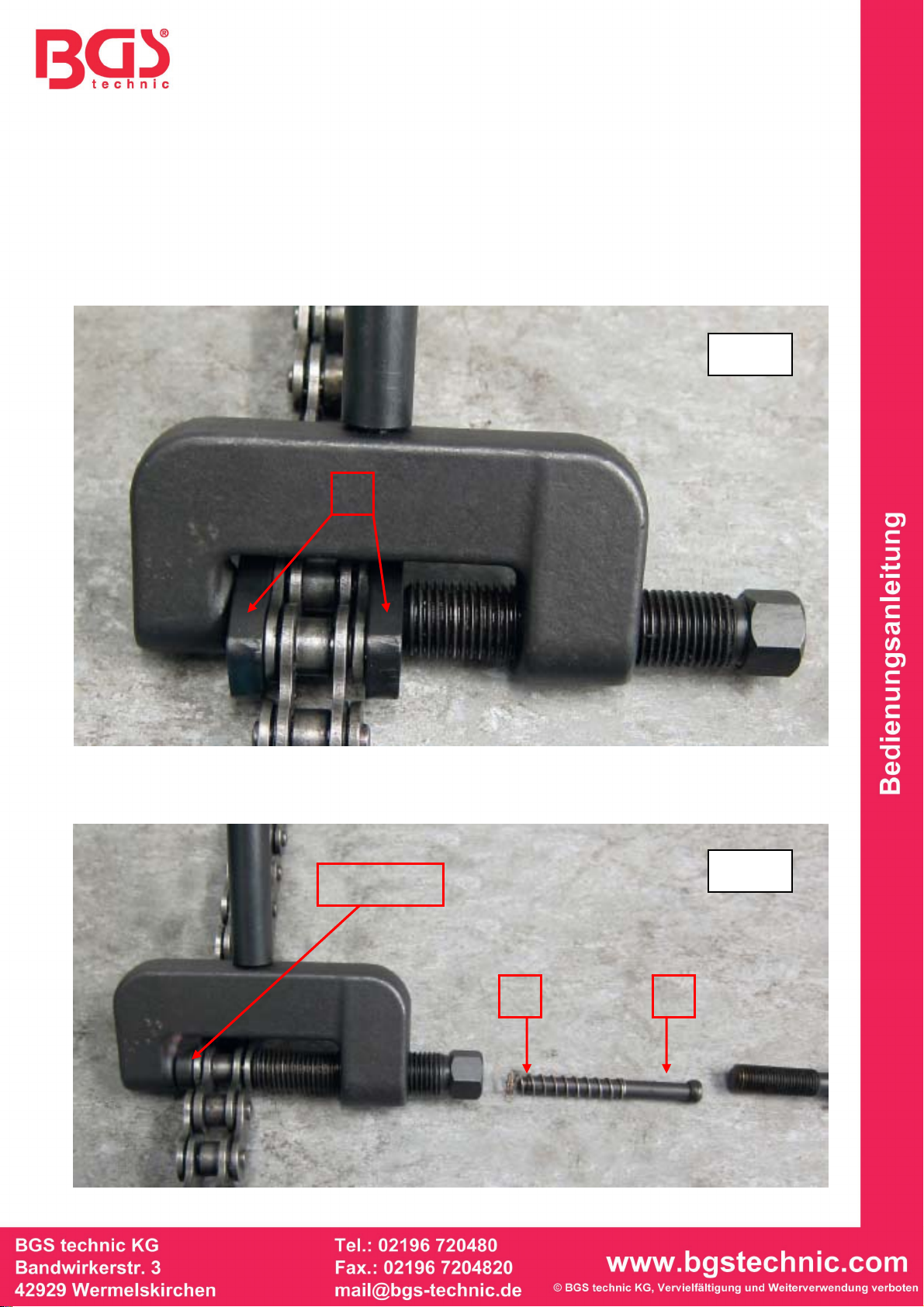
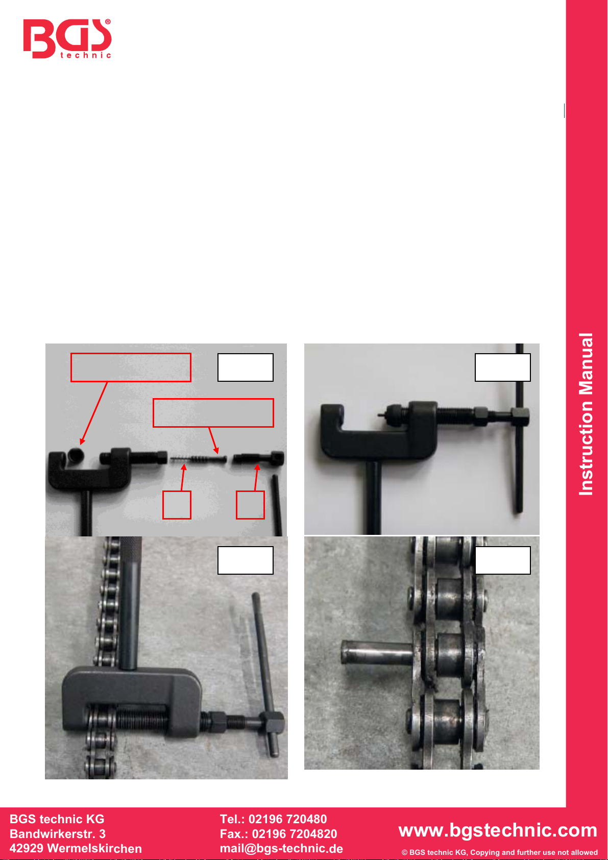
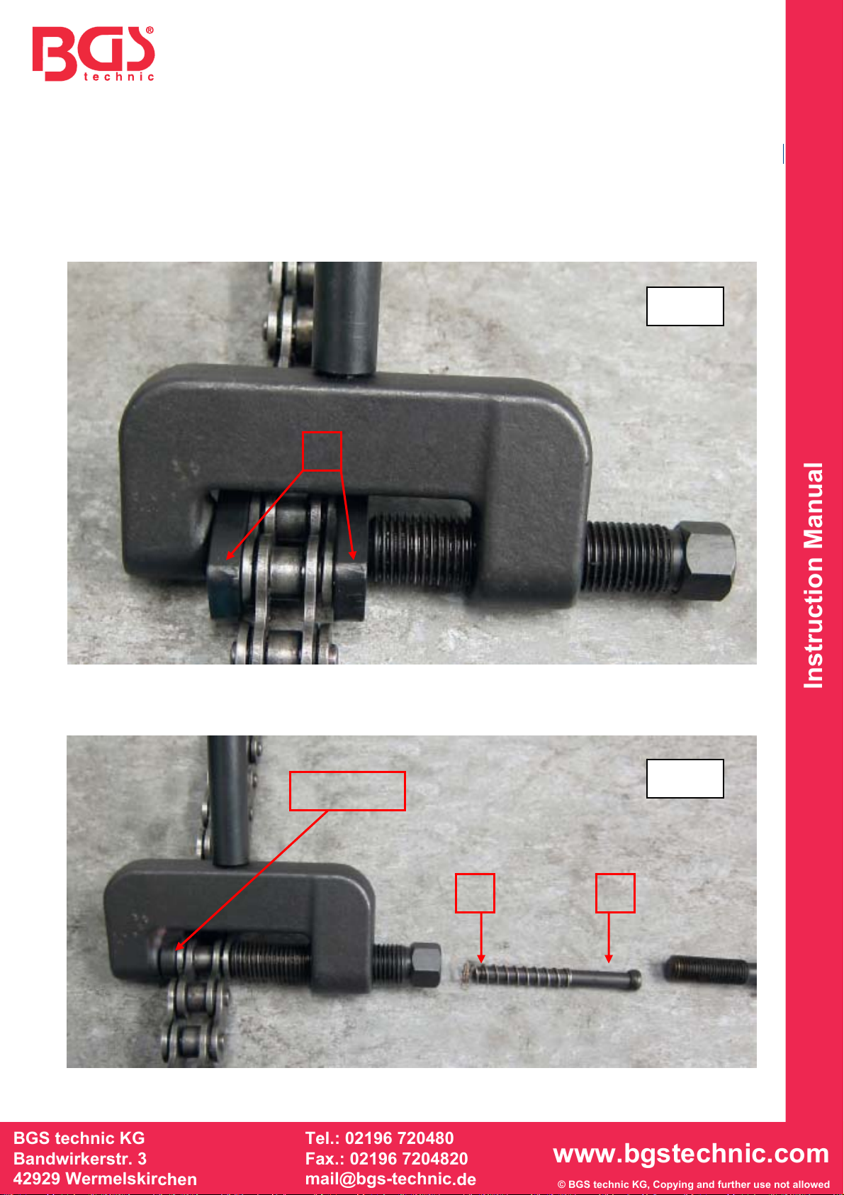
3. A comprehensive chain link splitter and riveting tool for removing and fitting motorcycle drive
chains and timing chains.
TOOLS
A Tool Body K Return spring for F2, G2, H2, I2, J
B Main Alignment Bolt L Large Anvil
C Force Screw M Small Anvil with adjustable centre pin
D Force Screw T Bar N Flat anvil
O Side Plate Clamp Pieces
E Tool Body Handle P Key for M
F1 Upper Guide for F2 F2 Force Pin 4.8 mm
G1 Upper Guide for G2 G2 Force Pin 3.8 mm
H1 Upper Guide for H2 H2 Force Pin 2.9 mm
I1 Upper Guide for I2 I2 Force Pin 2.2 mm
Q Chain stretcher
J Rivet Forming Pin,
for hollow nosed master links only R Chain Clip Fitting/Removal Pliers
A
B C
D E
F1
G1 I1
H1F2
G2 H2
I2
K
J
Q R
L M N O P