R&G CR0079 User manual

Page 1of 12
CR0079
R&G
Unit 1, Shelley’s Lane, East Worldham, Alton, Hampshire, GU34 3AQ
FITTING INSTRUCTIONS FOR CR0079 OFFSET COTTON REELS
FOR YAMAHA XTZ 700 (TENERE) 2019-
PICTURE A PICTURE B
THIS KIT CONTAINS THE ITEMS PICTURED AND LABELLED OVER PAGE.
SOME PARTS MAY BE SHOWN FOR CLARITY OF INSTRUCTIONS ONLY.
DO NOT PROCEED UNTIL YOU ARE SURE ALL PARTS ARE PRESENT.
PLEASE READ ALL INSTRUCTIONS BEFORE PROCEEDING.
IF IN ANY DOUBT WHEN FITTING OUR PRODUCTS, CONSULT ONE OF
OUR DEALERS OR HAVE FITTED BY A QUALIFIED TECHNICIAN.
PLEASE NOTE THAT THE WAY THE KIT IS PACKED DOES NOT NECESSARILY REPRESENT THE
WAY OF MOUNTING TO THE BIKE.
IN THE EVENT OF RUBBER WASHERS BEING USED TO HOLD COMPONENTS ONTO BOLTS,
THESE RUBBER WASHERS CAN BE THROWN AWAY.
DIGITAL COPIES OF THESE INSTRUCTIONS ARE AVAILABLE FROM:
WWW.RG-RACING.COM

Page 2of 12
CR0079
R&G
Unit 1, Shelley’s Lane, East Worldham, Alton, Hampshire, GU34 3AQ
TOOLS REQUIRED
•Socket set to include 27mm A/F socket
and wrench.
•Set of metric Allen keys or socket bits to
include 8mm A/F size.
•Torque wrench.
GENERAL TORQUE SETTINGS
M4 BOLT = 8Nm
M5 BOLT = 12Nm
M6 BOLT = 15Nm
M8 BOLT = 20Nm
M10 BOLT = 40Nm
M12 BOLT = 40Nm
LEGEND
ITEM NO.
DESCRIPTION
QTY
ITEM 1
LEFT HAND SIDE REPLACEMENT ADJUSTER BLOCK/COTTON
REEL MOUNT (M0376)
1
ITEM 2
COTTON REEL (B0443) FITTED WITH COMPRESION SLEEVE
(CS303)
2
ITEM 3
M10 WASHERS
2
ITEM 4
M10 x 1.25 x 40mm LONG CAP HEAD BOLT
2
ITEM 5
M10 BOLT COVERS (NC0010)
2
ITEM 6
RIGHT HAND SIDE REPLACEMENT ADJUSTER BLOCK/COTTON
REEL MOUNT (M0377)
1

Page 4of 12
CR0079
R&G
Unit 1, Shelley’s Lane, East Worldham, Alton, Hampshire, GU34 3AQ
FITTING INSTRUCTIONS
Please read all instructions before commencing fitting
•Raise rear of bike we suggest lifting from the swing arm, support rear wheel (we suggest using
blocks of wood) to prevent wheel from dropping when rear spindle is removed.
•Undo the rear spindle nut.
•Remove the rear spindle and remove the original chain adjuster blocks.
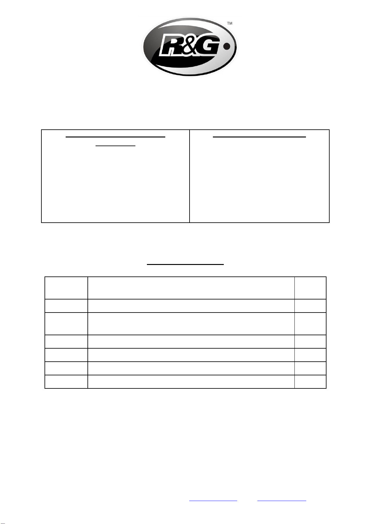
•Place rear spindle through new adjuster block (item 6 with the smaller slot to fit the head of
the spindle) with the groove facing away from the wheel so the groove is visible on assembly.
•Slide the spindle assembly through swing arm from the right-hand side, brake calliper and rear
wheel ensuring new adjuster block sits in the recess as original (as shown in picture B).
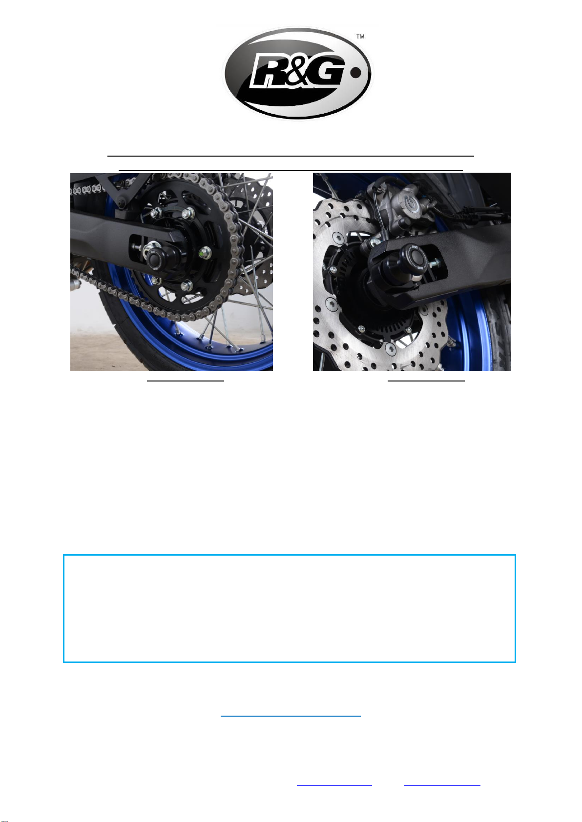
•Fit the remaining new adjusting block (item 1 with the larger slot for the nut and washer) over
the exposed end of spindle on the left-hand side with the groove facing away from the wheel
so the groove is visible on assembly as shown in picture A.
•Refit the original spindle nut with the original washer (as shown in picture A) and tighten
according to the manufacture’s instructions and check chain adjustment. Please note the new
adjuster blocks have an engraved line to aid with adjustment.
•Fit the new cotton reels (item 2) to the new adjuster blocks using the M10 cap head bolts
(item 4) with washers (item 3) on both sides as shown in pictures A and B.
•Fit the bolt covers (item 5) to both bolts.
ISSUE 1 03/12/2019 (NSY)
CONSUMER NOTICE
The catalogue description and any exhibition of samples are only broad indications of the Products and R&G
may make design changes which do not diminish their performance or visual appeal and supplying them in
such state shall conform to the order. The Buyer acknowledges no representation or warranty (other than as to
title) has been given or will apply to the Products other than those in R&G’s order or confirmation and the
Buyer confirms it has chosen the Products as being of merchantable quality and suitable for its particular
purposes. Where R&G fits the Products or undertakes other services it shall exercise reasonable skill and care
and rectify any fault free of charge unless the workmanship has been disturbed. The Buyer is responsible for
ensuring that the warranty on the motorcycle is not affected by the fitting of the Products. On return of any
defective Products R&G shall at its option either supply a replacement or refund the purchase money but shall
not be liable if the Products have been modified or used or maintained otherwise than in accordance with
R&G’s or manufacturer’s instructions and good engineering practice or if the defect arises from accident or
neglect. Other than identified above and subject to R&G not limiting its liability for causing death and personal
injury, it shall not be liable for indirect or consequential loss and otherwise its liability shall be limited to the
amounts paid by the Buyer for the Products or the fitting or service concerned. These terms do not affect the
Buyer’s statutory rights.
R&G RETURNS POLICY (NON-FAULTY GOODS)
Returns must be pre-authorised (if not pre-authorised the return will be rejected). Goods may only be returned
direct to us if they were purchased direct from us (customer must prove if necessary). Otherwise to be
returned to original vendor. Goods must be in re-sellable condition, in the opinion of R&G. All returns are
subject to a 25% restocking and handling fee (25% of the gross value exc. P&P –at the prevailing price at
time of purchase). The customer must pay any and all carriage charges. No returns of discontinued products,
unless within 14 days of purchase. This policy does not affect your statutory rights and does not refer to faulty
goods.

Page 5of 12
CR0079
R&G
Unit 1, Shelley’s Lane, East Worldham, Alton, Hampshire, GU34 3AQ
NOTICE DE MONTAGE POUR CR0079 PROTECTION CRASH
POUR YAMAHA XTZ 700 (TENERE) 2019-
PHOTO A PHOTO B
LE KIT CONTIENT LES ARTICLES EN PHOTO ET ETIQUETTES SUR LA PAGE
LES PARTIES PRESENTÉES PEUVENT ETRE UNIQUEMENT
REPRESENTATIVES POUR LA CLARTE DES INSTRUCTIONS
NE PAS PROCEDER AU MONTAGE AVANT DE VOUS ETRES ASSURE QUE TOUTES LES
PIECES SOIENT PRESENTES.
SVP, LIRE L’ENSEMBLE DE LA NOTICE AVANT DE PROCEDER AU MONTAGE.
EN CAS DE DOUTE LORS DU MONTAGE, CONSULTEZ UN DE NOS REVENDEURS, OU
FAITES EFFECTUER LE MONTAGE PAR UN TECHNHICIEN QUALIFIE.
LA FAÇON DONT LE KIT EST EMBALLE NE CORRESPOND PAS FORCEMENT A LA FAÇON DE
MONTER LES PIECES SUR LA MOTO.
NOTEZ QUE SI LES KITS SONT EMBALLES AVEC DES RONDELLES EN CAOUTCHOUC
SERVANT A TENIR LES COMPOSANTS,CES RONDELLES DOIVENT ETRE JETEES.
NOTICE DISPONIBLE AU TELECHARGEMENT SUR :
WWW.RG-RACING.COM

Page 6of 12
CR0079
R&G
Unit 1, Shelley’s Lane, East Worldham, Alton, Hampshire, GU34 3AQ
OUTILS REQUIS
• Clé à cliquet + douille 27mm.
•Clé Allen 8mm
•Clé dynamométrique
VALEURS DE SERRAGE
M4 BOULON =8NM
M5 BOULON =12NM
M6 BOULON =15NM
M8 BOULON =20NM
M10 BOULON =40NM
M12 BOULON =40NM
LEGENDE
ARTICLE
NO.
DESCRIPTION
QTE
ARTICLE 1
SUPPORT D’AJUSTEUR DE PROTECTION COTE GAUCHE
(M0376)
1
ARTICLE 2
BOBINE DE PROTECTION (B0443) AVEC MANCHON DE
COMPRESSION (CS303)
2
ARTICLE 3
M10 RONDELLES
2
ARTICLE 4
M10 x 1.25 x 40mm BOULONS
2
ARTICLE 5
M10 CACHES BOULONS (NC0010)
2
ARTICLE 6
SUPPORT D’AJUSTEUR DE PROTECTION COTE DROIT
(M0377)
1

Page 8of 12
CR0079
R&G
Unit 1, Shelley’s Lane, East Worldham, Alton, Hampshire, GU34 3AQ
NOTICE DE MONTAGE
SVP, LIRE L’ENSEMBLE DE LA NOTICE AVANT DE PROCEDER AU MONTAGE.
•Relevez l'arrière de la moto, nous vous suggérons de le soulever au niveau du bras oscillant,
de soutenir la roue arrière (nous suggérons d'utiliser des blocs de bois) pour éviter que la roue
ne tombe lorsque l’axe arrière sera retiré.
•Desserrez l'écrou d’axe arrière.
•Retirez l'axe arrière et retirez les blocs de réglage de chaîne d'origine.
•Placer l’axe arrière à travers le nouveau bloc de réglage (article 6 avec la plus petite fente pour
s'adapter à la tête de l’axe) avec la rainure espacée de la roue de sorte que la rainure soit
visible lors du montage.
•Faites glisser l'ensemble de l’axe à travers le bras oscillant du côté droit, l'étrier de frein et la
roue arrière en vous assurant que le nouveau bloc de réglage se trouve dans l'évidement
comme à l’origine (comme illustré sur la photo B).
•Montez le nouveau bloc de réglage restant (article 1 avec la plus grande fente pour l'écrou et
la rondelle) sur l'extrémité exposée de l’axe sur le côté gauche avec la rainure tournée vers
l'opposé de la roue de sorte que la rainure soit visible sur l'assemblage comme illustré dans
photo A.
•Remontez l’écrou d’axe d'origine avec la rondelle d'origine (comme indiqué sur la photo A) et
serrez selon les instructions du fabricant et vérifiez le réglage de la chaîne. Veuillez noter que
les nouveaux blocs de réglage possèdent une ligne gravée pour faciliter le réglage.
•Montez les nouvelles bobines de protection (article 2) sur les nouveaux blocs de réglage en
utilisant les boulons à tête cylindrique M10 (article 4) avec des rondelles (article 3) des deux
côtés comme indiqué sur les photos A et B.
•Monter les cache-boulons (article 5) sur les deux boulons.
ISSUE 1 03/12/2019 (NSY)

Page 9of 12
CR0079
R&G
Unit 1, Shelley’s Lane, East Worldham, Alton, Hampshire, GU34 3AQ
MONTAGEANLEITUNG FÜR CR0079 MONTAGESTÄNDER-
AUFNAHMEN FÜR YAMAHA XTZ 700 (TENERE) 2019-
ABBILDUNG A ABBILDUNG B
ALLE KIT-TEILE SIND AUF DEN FOLGENDEN SEITE ABGEBILDET UND GEKENNZEICHNET
DIE ABGEBILDETEN TEILE DIENEN LEDIGLICH ZUR ERKLÄRUNG.
ÜBERPRÜFEN SIE ZUERST,DASS ALLE TEILE VORHANDEN SIND.
LESEN SIE DIE MONTAGEANLEITUNG KOMPLETT DURCH,BEVOR SIE ANFANGEN.
WENN SIE BEI DER MONTAGE DIESES PRODUKTES UNSICHER SIND,
BITTE EINEN UNSERER HÄNDLER KONTAKTIEREN ODER DAS KIT VON
EINEM QUALIFIZIERTEN ZWEIRAD-MECHANIKER MONTIEREN LASSEN.
DIE VERPACKUNG DER TEILE STELLT NICHT DIE REIHENFOLGE DER MONTAGE DAR.
HINWEIS FÜR KITS MIT PLASTIKUNTERLEGSCHEIBEN AN DEN SCHRAUBEN –DIESE
PLASTIK-UNTERLEGSCHEIBEN WERDEN NICHT FÜR DEN EINBAU BENÖTIGT!
EINE DIGITALE VERSION DIESER MONTAGEANLEITUNG KANN AUF
FOLGENDER SEITE HERUNTERGELADEN WERDEN:
WWW.RG-RACING.COM

Page 10 of 12
CR0079
R&G
Unit 1, Shelley’s Lane, East Worldham, Alton, Hampshire, GU34 3AQ
SIE BENÖTIGEN FOLGENDES
WERKZEUG
• Satz Steckschlüssel inkl. 27mm A/F
• Satz Inbusschlüssel oder Einsätze inkl. Gr.
8mm A/F
•Drehmomentschlüssel
ALLGEM.ANZUGSDREHMOMENTE
M4 SCHRAUBE = 8Nm
M5 SCHRAUBE = 12Nm
M6 SCHRAUBE = 15Nm
M8 SCHRAUBE = 20Nm
M10 SCHRAUBE = 40Nm
M12 SCHRAUBE = 40Nm
LIEFERUMFANG
ARTIKEL
NO.
BESCHREIBUNG
MENGE
ARTIKEL 1
LINKE SEITE ERSATZ VERSTELLBARE HALTEPLATTE (M0376)
1
ARTIKEL 2
MONTAGESTÄNDERAUFNAHMEN (B0443) MIT
KOMPRESSIONSSCHLAUCH (CS303)
2
ARTIKEL 3
M10 UNTERLEGSCHEIBE
2
ARTIKEL 4
M10 x 1,25 x 40mm INBUSSCHRAUBE
2
ARTIKEL 5
M10 SCHRAUBEN-ABDECKUNG (NC0010)
2
ARTIKEL 6
RECHTE SEITE ERSATZ VERSTELLBARE HALTEPLATTE (M0377)
1

Page 12 of 12
CR0079
R&G
Unit 1, Shelley’s Lane, East Worldham, Alton, Hampshire, GU34 3AQ
MONTAGEANLEITUNG
Bitte die Montageanleitung komplett durchlesen, bevor Sie mit der
Montage beginnen.
•Das Heck anheben (wir empfehlen, von der Schwinge anheben) und das Hinterrad dabei
stützen (wir empfehlen Holzblöcke), um zu vermeiden, dass das Rad runterfällt, wenn die
hintere Radachse entfernt wird.
•Lösen Sie die hintere Achsmutter.
•Entfernen Sie die hintere Radachse und entfernen Sie die original Kettenspannerplatten.
•Die hintere Radachse durch die neue verstellbare Halteplatte führen (Artikel 6 mit der
kleineren Vertiefung für den Kopf der Radachse passend). Die Rille soll hierbei weg vom Rad
gerichtet sein, so dass die Rille bei der Montage ersichtlich ist.
•Von der rechten Seite beginnend, schieben Sie die Achseinheit in die Schwinge, durch den
Bremssattel und das Hinterrad, und stellen Sie sicher, dass der neue verstellbare
Halteplatte/Montageplatte in die Vertiefung passt wie ursprünglich (siehe Abbildung B).
•Montieren Sie die übrige verstellbare Halteplatte (Artikel 1 mit der größeren Öffnung für die
Mutter und Unterlegscheibe) am hervorstehenden Ende der Radachse an der linken Seite. Die
Rille soll hierbei weg vom Rad gerichtet sein, so dass die Rille bei der Montage ersichtlich ist
(siehe Abbildung A).
•Montieren Sie die original Achsmutter mit der original Unterlegscheibe wieder (siehe
Abbildung A) und mit dem empfohlenen Anzugsdrehmoment des Herstellers festziehen.
Überprüfen Sie die Kettenspannung. Hinweis: die neuen verstellbaren Halteplatten sind mit
einer eingravierten Linie versehen, um bei der Einstellung zu helfen.
•Montieren Sie die neuen Montageständeraufnahmen (Artikel 2) an den neuen verstellbaren
Halteplatten/Montageplatten –benutzen Sie hierfür die M10 Inbusschrauben (Artikel 4) mit
Unterlegscheiben (Artikel 3) an beiden Seiten wie in den Abbildungen A und B abgebildet.
•Montieren Sie die Schrauben-Abdeckungen (Artikel 5) an beiden Schrauben.
AUSGABE 1 03/12/2019 (NSY)
Table of contents
Other R&G Motorcycle Accessories manuals
Popular Motorcycle Accessories manuals by other brands

Cyclevision
Cyclevision EDGE CVHC-01-01 instruction manual

DYNATEK
DYNATEK D3K2-1 installation instructions

Uclear
Uclear HBC220 SNOW user manual

hepco & becker
hepco & becker 630734 00 01 Mounting instructions

Rekluse Motor Sports
Rekluse Motor Sports RadiusCX Clutch Installation & user guide

Urrea
Urrea USCS6 User manual and warranty