BGS technic 8688 User manual

SW-Stahl und Werkzeugvertriebs GmbH Tel. +49 (0) 2191 / 46438-0
F56essartSresukreveL ax +49 (0) 2191 / 46438-40
ed.lhatsws@ofni:liaM-EdiehcsmeR79824-D
Instruction Manual
BGS technic KG
Bandwirkerstr. 3
D-42929 Wermelskirchen
Tel.: 02196 720480
Fax.: 02196 7204820
www.bgstechnic.com
© BGS technic KG, Copying and further use not allowed
Art. 8688
Air Eccentric Sander
SPECIFICATION
Pad Size: 152 mm (6")
Free Speed: 10,000 rpm
Working Pressure: 6,3 Bar (90 psi)
Avg. Air Consumption: 142 L/min (5 CFM)
Air Inlet: 1/4"
min. Hose Ø: 10 mm (3/8")
Weight: 1050 g
Overall length: 225 mm
Noise: LPA: 87dB(A) / LWA: 98dB(A)
Vibration: ah = 8.5 m/s² / K= 1.5 m/s²
IMPORTANT SAFETY INFORMATION
WARNING!
Read and understand and follow all instructions and warnings before operating this tool.
Failure to do so may result in personal injury and/or property damage and will void warranty.
Oil tool before each use 4 to 5 drops of a good grade Air Tool Oil placed in the air inlet is sufficient.
Use proper air pressure and CFM rating listed for this tool.
1. Be sure air is in OFF position when connecting tool to air supply.
2. Always wear approved eye protection when using tools. If raising dust, wear a suitable mask.
3. Use only those accessories that are designed for use with tools.
4. Be sure to disconnect tool from air supply before changing accessories, performing service on
tool, and when not in use.
5. As with any tool, use common sense when operating. Do not wear loose clothing or jewelry that
could become caught by moving parts, causing injury. Operate tool a safe distance from yourself
and others in the work area.
6. Follow air source manufacturers directions for connection of regulators, filters, and other
accessories to air source. Do not install quick couplers directly on tool as they put unnecessary
strain on the air inlet threads possibly causing them to wear out prematurely. Instead, install them
on a short length of air hose attached to the tool.

SW-Stahl und Werkzeugvertriebs GmbH Tel. +49 (0) 2191 / 46438-0
F56essartSresukreveL ax +49 (0) 2191 / 46438-40
ed.lhatsws@ofni:liaM-EdiehcsmeR79824-D
Instruction Manual
BGS technic KG
Bandwirkerstr. 3
D-42929 Wermelskirchen
Tel.: 02196 720480
Fax.: 02196 7204820
www.bgstechnic.com
© BGS technic KG, Copying and further use not allowed
AIR SOURCE
Clean air of correct air pressure is recommended for the power supply for this tool. A maximum of 90
PSI at the tool is recommended for most air tools of this class. Check specifications section for
recommended pressure. (Depending on length of air hose and other circumstances, air pressure at
compressor may need to be increased to 100 PSI to ensure 90 PSI at the tool.) Water in the air hose
and compressor tank contributes to reduced performance and damage of the air tool. Drain the air
tank and filters before each use and as necessary to keep the air supply dry. Hose length over 25”
causes loss in line pressure. Increase hose ID or increase compressor pressure to compensate
for the pressure loss. Use an in-line pressure regulator with gauge if air inlet pressure is critical.
1
Tool
6
Shut Off Valve
11
Air Dryer
2
Air Hose
7
Whip Hose
12
1“ Or Larger Pipe
3
Oiler
8
Connector
13
Air Compressor
4
Pressure Regulator
9
Drain Valve (Drain Daily)
14
Auto Drain
5
Filter
10
½“ or Larger Pipe
15
Drain Valve (Drain Daily)
LUBRICATION & MAINTENACE
Warning!
Oil tool before each use. 4 to 5 drops Air Tool Oil placed in the air inlet is sufficient.
Use proper air pressure and CFM rating listed for this tool.
Drain water from hoses and compressor tank.
Water in the air supply line demage the tool and loss of power.
Clean or replace air filters at prescribed intervals.
TROUBLESHOOTING
Insufficient power:
Probable Cause
Solution
Dirty or clogged air passages Flush and lubricate tool, drain air tank and supply line
Insufficient air supply Increase line pressure, make sure compressor matches
tool's air pressure and consumption needs
Air leakage Use teflon tape at all fittings and joints.
Check tool for worn or damaged o-rings & seals.
Worn/damaged wear & tear parts Replace as necessary
Tool matching Be sure you are using a tool suited for the sanding
requirements of the job at hand.
SW-Stahl und Werkzeugvertriebs GmbH Tel. +49 (0) 2191 / 46438-0
F56essartSresukreveL ax +49 (0) 2191 / 46438-40
ed.lhatsws@ofni:liaM-EdiehcsmeR79824-D
Instruction Manual
BGS technic KG
Bandwirkerstr. 3
D-42929 Wermelskirchen
Tel.: 02196 720480
Fax.: 02196 7204820
www.bgstechnic.com
© BGS technic KG, Copying and further use not allowed
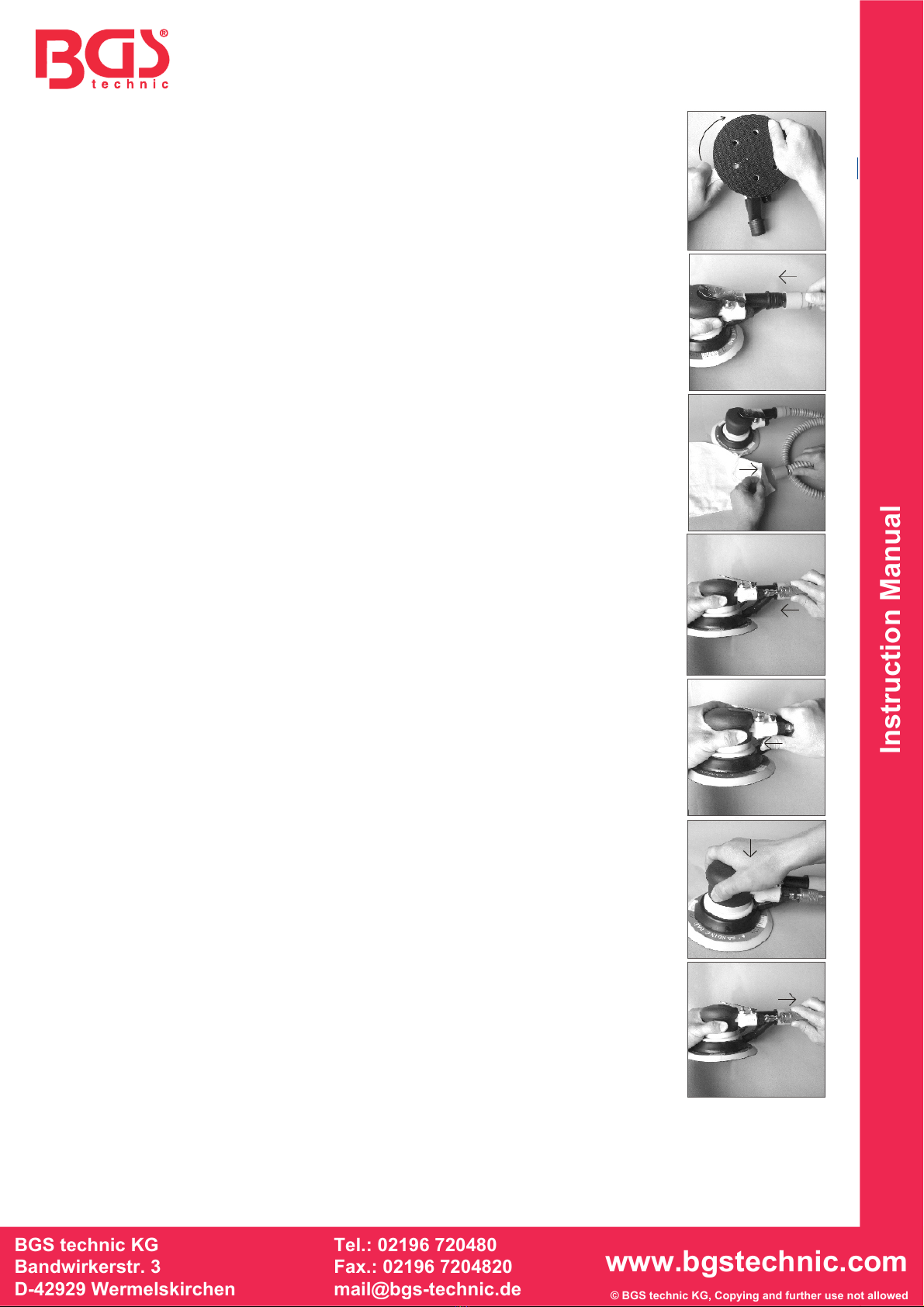
OPERATION INSTRUCTIONS
1. Lubricate the tool before operating.
See “CARE AND MAINTENANCE” section for oiling instructions.
2. Disconnect tool from air supply. (Fig.7)
3. Screw tight by hand at clockwise direction the sanding pad
into the female thread of the bearing stand (Part #21) while
holding the provided wrench on the flats of the stand as
shown. (Fig.1)
4. Mount a sanding paper (not provided) onto the sanding pad.
5. Connect the dust tube to the dust tube connector (Part #32)
and set it secure. (Fig.2)
6. Mount the dust bag to the dust tube by tying the string tight
around the tube end. (Fig.3)
7. Remove the air cap from the tool air inlet and connect the air
supply hose to the tool. Set the air pressure at 90 PSI. (Fig.
4)
WARNING: When connecting the air hose, keep the speed control
knob (i.e. trigger valve - Part #26) in “OFF” position by turning the
knob backwards to the upmost. (Fig.5)
8. Turn the speed control knob forwards to the upmost, hold
the tool by one hand and slowly press down on the trigger by
your palm to the upmost. Then the tool starts to work. (Fig.6)
NOTE You can control the air flow and rotation speed by turning the
speed control knob.
REPLACEMENT OF SANDING PAD
1. Disconnect the tool from air supply. (Fig.7)
2. Rotate with hand counter clockwise the sanding of the
female thread of the bearing stand while holding the
provided wrench on the flats of the stand.
3. Replace a new sanding pad in the same way as said at the
above Point 3 in “OPERATION INSTRUCTIONS” section.
WARNING: Only use sanding pads that have an RPM rating equal
to or greater than the tool itself.
CARE AND MAINTENANCE
The tool should be lubricated daily (or before each use) with air tool
oil (not included).
NOTE: Air tool oil is available at major tool hardware stores. SAE
#10 weight oil or sewing machine lubricant or any other high grade
turbine oil containing moisture absorbent, rust inhibitors, metal
wetting agents and an EP (extreme pressure) additive may be used
as a substitute. Do not use detergent oil. During continuous
operation, the tool should be oiled every 1 to 2 hours. This may be
done using an in-line oiler, or manually. If done manually, proceed
as follows:
1. Disconnect the tool from air supply. (Fig.7)
2. Place a few drops of air tool oil into the air inlet. (Fig.8)
NOTE: Avoid the misuse of thicker oil which may lead to the
reduced performance or malfunction.
Fig.1
Fig.2
Fig.3
Fig.4
Fig.5
Fig.6
Fig.7

SW-Stahl und Werkzeugvertriebs GmbH Tel. +49 (0) 2191 / 46438-0
F56essartSresukreveL ax +49 (0) 2191 / 46438-40
ed.lhatsws@ofni:liaM-EdiehcsmeR79824-D
Instruction Manual
BGS technic KG
Bandwirkerstr. 3
D-42929 Wermelskirchen
Tel.: 02196 720480
Fax.: 02196 7204820
www.bgstechnic.com
© BGS technic KG, Copying and further use not allowed
3. Connect the tool to the air supply. Run the tool without load
for a few seconds to distribute the oil through the tool. Any
excess oil may be propelled from the air exhaust area. So
keep the tool away in a safe direction.
4. After operating the tool and before storing the tool,
disconnect the air hose and place 4 or 5 drops of air tool oil
into the air inlet, then re-connect the air hose and run the
tool to evenly distribute the oil throughout the tool for 30
seconds approximately. This will prolong the tool life.
5. Avoid storing the tool in a humid environment which
promotes rusting of internal mechanisms. Always oil the tool
before storage.
6. When the tool is seriously damaged or out of life, it should
be left in a resource recycling can. Never drop it into fire.
Fig.8
1
Main housing
15
Semi-round key
29
Nut
2
Head cover
16
Screw
30
O-ring
3
Washer
17
Bearing
31
Lever
4
Bearing
18
Wool ring
32
Dust tube connector
5
Bolt
19
Washer
33
O-ring
6
Rear plate
20
E-clip
34
Muffler
7
Rotor
21
Bearing stand
35
Dust connector accessory (1)
8
Rotor blade
22
Dust cover
36
Dust connector accessory (2)
9
Cylinder
23
Sanding pad
37
Lubricating ring
10
Front plate
24
Trigger
38
Tilting valve
11
Bearing
25
Trigger bolt
39
Spring
12
O-ring
26
Trigger valve
40
Air inlet
13
Fixing ring
27
O-ring
41
Dust tube
14
Rotating axle
28
Cushion
42
Dust collecting bag
SW-Stahl und Werkzeugvertriebs GmbH Tel. +49 (0) 2191 / 46438-0
F56essartSresukreveL ax +49 (0) 2191 / 46438-40
ed.lhatsws@ofni:liaM-EdiehcsmeR79824-D
CE-Erklärung
BGS technic KG
Bandwirkerstr. 3
42929 Wermelskirchen
Tel.: 02196 720480
Fax.: 02196 7204820
www.bgstechnic.com
EU-Konformitätserklärung
EC DECLARATION OF CONFORMITY
DÉCLARATION „CE“ DE CONFORMITE
DECLARATION DE CONFORMIDAD UE
Wir erklären in alleiniger Verantwortung, dass die Bauart der:
We declare that the following designated product:
Nous déclarons sous propre responsabilité que ce produit:
Declaramos bajo nuestra sola responsabilidad que este producto:
Druckluft-Exzenterschleifer ( BGS Art. 8688 )
Air Eccentric Sander
Ponceuse orbitale air comprimé
Lijadora orbital de aire comprimido
folgenden einschlägigen Bestimmungen entspricht:
complies with the requirements of the:
est en conformité avec les réglementations ci-dessous :
esta conforme a las normas :
Machinery Directive 2006/42/EC
Angewandte Normen:
Identification of regulations/standards:
Norme appliquée:
Normas aplicadas:
EN ISO 11148-8:2011
Verification No. SH12111317-V1/AT991L
Report No. SH12111317-001
Wermelskirchen, den 02.05.2013
ppa.
Frank Schottke, Prokurist
BGS technic KG, Bandwirkerstrasse 3, D-42929 Wermelskirchen
Other manuals for 8688
1
Table of contents
Other BGS technic Sander manuals


