Palmgren 9681062 Instructions for use

Operating Instructions & Parts Manual EN
1” x 42” Belt /
8” Disc Sander
Model 9681062
9642804.01

PLEASE READ AND SAVE
THESE INSTRUCTIONS.
READ CAREFULLY
BEFORE ATTEMPTING
TO ASSEMBLE, INSTALL,
OPERATE OR MAINTAIN THE
PRODUCT DESCRIBED.
PROTECT YOURSELF AND
OTHERS BY OBSERVING ALL
SAFETY INFORMATION. FAILURE
TO COMPLY WITH INSTRUCTIONS
COULD RESULT IN PERSONAL
INJURY AND/OR PROPERTY
DAMAGE! RETAIN INSTRUCTIONS
FOR FUTURE REFERENCE.
PLEASE REFER TO BACK COVER
FOR INFORMATION REGARDING
PALMGREN'S WARRANTY
AND OTHER IMPORTANT
INFORMATION.
Model #: ___________________
Serial #: ___________________
Purch. Date: _______________
© 2018 Palmgren / a C.H. Hanson Brand
All Rights Reserved

3
GETTING STARTED SAFETY / SPECIFICATIONS ASSEMBLY / INSTALLATION OPERATION TROUBLESHOOTING MAINTENANCE / REPAIR
GETTING STARTED
Save this manual
You will need this manual for the safety warnings and
precautions, assembly instructions, operating and maintenance
procedures, parts list and diagram. Keep your invoice with this
manual. Write the invoice number on the inside of the front cover.
Keep this manual and invoice in a safe and dry place for future
reference.
Structural requirements
Make sure all supporting structures and load attaching
devices are strong enough to hold your intended loads.
If in doubt, consult a qualified structural engineer.
Electrical requirements
The power supply to the Model 9681062 Belt / Disc
Sander is 115V, 60Hz, 5.8 amps. The standard
allowable voltage variation is a plus or minus 10%.
UNPACKING
When unpacking, check to make sure all parts listed below are
included. If any parts are missing or broken, please contact your
local retailer.
Never use highly volatile solvents. Avoid
getting cleaning solution on paint as it
may tend to deteriorate these finishes. Use soap and water
on painted components.
IMPORTANT: Many unpainted steel surfaces will have been
coated with a protectant. To ensure proper fit and operation,
remove the coating. Coating can be easily removed with mild
solvents, such as mineral spirits and a soft cloth. Avoid getting
solution on paint or any of the rubber/plastic parts. Solvents may
deteriorate these finishes. Use soap and water on paint, plastic
or rubber components. After cleaning, cover all exposed surfaces
with a light coating of oil.
Contents:
• Motor and Base Assembly
• Belt Housing Assembly
• Belt Sanding Table
• Motor Belt Cover
• Disc Sanding Table
• 8” Sanding Disc
• 8” PSA Sander Paper Disc
• V-Belt Rear Cover
• 2” Dust Port
• Disc Dust Cover
• Miter Gauge
• Table Lock Handles
• Hardware Pack with
Wrench and Miter Gauge
Holder
• 2.5 mm Hex Wrench
• 8 mm Hex Wrench
Unpack
Remove all the over packing materials, but leave unit
attached to its pallet. Do not discard packing materials
until after the machine has been inspected for damage and
completeness. Locate loose parts and set them aside.
Inspect
• After unpacking the unit, carefully inspect for any
damage that may have occurred during transit.
Check for loose, missing or damaged parts.
Shipping damage claims must be filed with the
carrier.
• All tools should be visually inspected before use, in addition to
regular periodic maintenance inspections.
• Be sure that the voltage labeled on the unit matches your
power supply.
SAFETY RULES
For your own safety, read all of the
instructions and precautions before
operating tool.
Always follow proper operating
procedures as defined in this manual even
if you are familiar with the use of this tool or similar
machines. Remember that being careless for even a fraction
of a second can result in severe personal injury.
PROPOSITION 65 WARNING: Some dust created by
using power tools contain chemicals known to the state
of California to cause cancer, birth defects or other
reproductive harm.
Some examples of these chemicals are:
• Lead from lead-based paints
• Crystalline silica from bricks and cement and other masonry
products
• Arsenic and chromium from chemically-treated lumber
Your risk from these exposures varies, depending on how often
you do this type of work. To reduce your exposure to these
chemicals: work in a well ventilated area and work with approved
safety equipment. Always wear a OSHA/NIOSH approved,
properly fitting face mask or respirator when using such tools.
Preparing for your job
• Wear safety glasses complying with United States ANSI
Z87.1. Everyday glasses only have impact resistant lenses.
They are not safety glasses.
• Wear an ANSI approved dust mask.
• Wear proper apparel when using this tool. Do not wear loose
clothing, gloves, neckties, rings, bracelets or other jewelry
which may get caught up in moving parts of this machine.
• When using this machine, wear protective hair covering to
contain long hair.
• Wear safety shoes with non-slip soles.
• Be alert and think clearly. Never operate power tools when
tired, intoxicated or when taking medications that cause
drowsiness.
Preparing the work area for your job
• Keep your work area clean. Cluttered work areas invite
accidents.

MAINTENANCE / REPAIR TROUBLESHOOTING OPERATION ASSEMBLY / INSTALLATION SAFETY / SPECIFICATIONS GETTING STARTED
4
• Do not set up or use the Belt / Disc Sander in dangerous
environments. Do not set up or use the Belt / Disc Sander in
damp or wet locations. Do not expose this machine to rain.
• Make sure your work area is properly lighted.
• Proper electrical connections should be set up for this
machine.
• Extension cords should have a grounding prong and the
three wires of the extension cord should be of the proper
gauge.
• Keep visitors at a safe distance from work area.
• Keep children out of the workplace. Make your workshop
childproof. Use padlocks, master switches or remove switch
keys to prevent any unintentional use of your power tools.
Maintaining your tool
• Always unplug the tool and remove it from its power source
prior to inspection or adjustment. If your machine plugs into
an electrical outlet do not unplug the tool by pulling on the
cord.
• Consult this manual for specific maintenance and adjustment
procedures.
• Keep the tool clean for safest operation. Wood dust build ups
can become combustible.
• Check for damaged parts. A part that is damaged should
be properly repaired or replaced. Do not perform makeshift
repairs. Use the parts list in this manual to order repair parts.
Repairs must be made by a qualified technician.
Know how to use your tool
Dusty work environments may be
hazardous to your health. Always wear a
OSHA/NIOSH approved, properly fitting face mask or
respirator.
The operation of any machine can result
in foreign objects being thrown into the
eyes, which can result in severe eye damage. Always wear
safety goggles complying with United States ANSI Z87.1.
(shown on package) before commencing power tool
operation.
Think safety! Safety is a combination of
operator common sense and alertness at
all times when tool is being used.
• Do not attempt to operate this tool until it is completely
assembled according to the directions in this manual.
• Do not turn ON this machine if parts are missing or damaged.
• It is highly recommended this machine be mounted on a level
surface or stand.
• Replace worn, frayed or torn abrasives, as injury to the user
or machine may result.
• Always keep your hands and face away from moving parts,
belts, discs and pulleys.
• Know your tool. Learn the tool’s operation, application and
specific limitations.
• Never operate the machine without the disc guards in place.
• Completely disconnect this machine from its power source
when changing an abrasive disc or belt.
• Use the right tool for the job. Do not force a tool or
attachment to do a job for which it was not designed.
• To reduce the risk of electrical shock, never use the machine
in rain or allow it to become wet.
• Never attach the Belt / Disc Sander to a dust extraction unit
used for wood sanding if you are sanding metal. The sparks
can cause a fire or explosion.
• Turn the tool off immediately in the case of an emergency.
Completely remove the tool from its power source before
attempting to fix the issue.
• Never leave tool running unattended. Turn the power off and
do not leave tool until it comes to a complete stop.
• Do not use the tool as a toy or let children play with it. Care
should be taken when using the tool around children or
animals.
• Avoid accidental start-ups. Make sure that the power switch
is in the OFF position before plugging the machine in or
connecting it into an appropriate electrical resource.
• Do not overreach. Keep proper footing and balance.
• Never stand on the machine. Serious injury could occur if the
tool tips or if the sanding disc is unintentionally contacted.
• Only use recommended accessories. The improper use of
accessories may create a risk of operator injury.
• Handle workpieces correctly to help protect your hands from
possible injury.
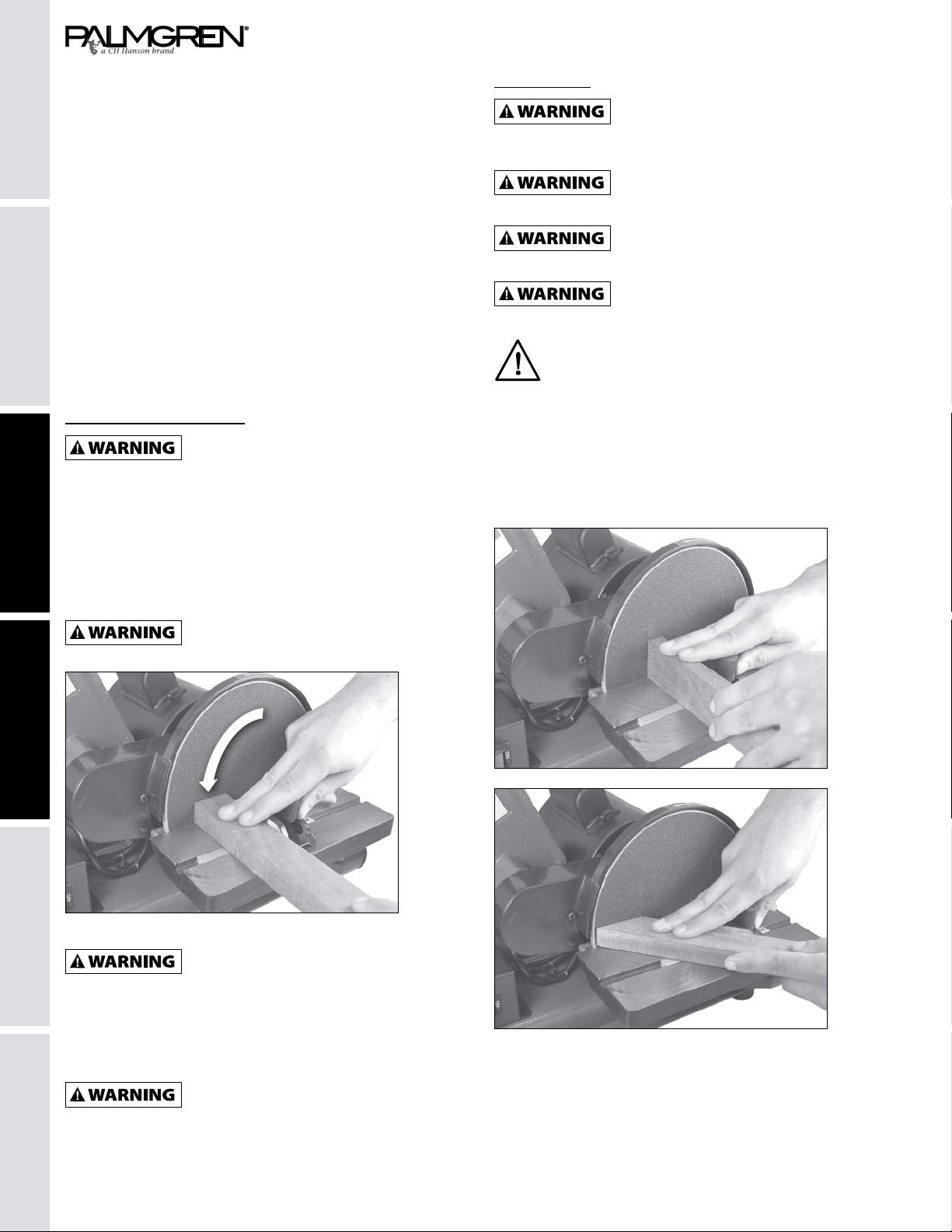
• Support your workpiece with the supplied miter gauge or the
work table. “Free-hand” sanding is not recommended.
• Maintain a 1/16” maximum clearance or less between table
and sanding disc or belt.
• Follow OSHA lock-out, tag-out procedures to prevent
accidental machine starts.
Electrical connections
Make sure the tool is off before plugging it
into a power source to prevent accidental
starts.
Do not permit fingers to touch the
terminals of plug when installing or
removing from outlet.
Electrical safety
• Double insulated tools are equipped with a polarizing three
pronged plug (one blade is wider than the other.) This plug
will fit in a polarized outlet only one way. If the plug does not
fit fully into the outlet, reverse the plug. If it still does not fit,
contact a qualified electrician to install a polarized outlet. Do
not change the plug in any way.
• Double insulation eliminates the need for the three wire
grounded power cord and grounded power supply system.
Before plugging in the tool, be certain the outlet voltage
supplied is within the voltage marked on the nameplate.
• Avoid body contact with grounded surfaces such as pipes,

5
GETTING STARTED SAFETY / SPECIFICATIONS ASSEMBLY / INSTALLATION OPERATION TROUBLESHOOTING MAINTENANCE / REPAIR
A.
radiators, ranges and refrigerators. There is an increased
risk of electric shock if your body is grounded. If operating
the power tool in damp locations is unavoidable, a Ground
Fault Circuit Interrupter must be used to supply the power to
your tool. Rubber soled footwear will further enhance your
personal safety.
4. Don’t expose this or any tools to rain or wet conditions. Water
entering a power tool will increase the risk of electric shock.
5. Do not abuse the cord. Never pull on a cord to unplug it from
an outlet. Keep the cord away from heat, oil, sharp edges
or moving parts. Replace damaged cords immediately.
Damaged cords increase the risk of electric shock.
Extension cords
• The use of an extension cord will cause some drop in voltage
and loss of power.
• Wires of the extension cord must be of sufficient size to carry
the current and maintain adequate voltage.
• Use the table to determine the minimum wire size (A.W.G)
extension cord.
• Use only 3-wire extension cords having 3-prong grounding
type plugs and 3-pole receptacles which accept the tool plug.
• If the extension cord is worn, cut or damaged in any way,
replace it immediately.
Extension cord length
Wire Size A.W.G.
Up to 25 ft 16
25 to 100 ft 14
NOTE: Using extension cords over 100 ft long is not
recommended.
SPECIFICATIONS
Model 9681062 - 8” Disc / 1” 42” Belt Sander
Motor 1/3 HP, 120V, 60Hz, 5.8 amps
Belt Speed (RPM) 3,000
Belt Size 1” x 42”
Disc Speed (RPM) 1,770
PSA Disc Size (dia.) 8”
Dust Ports (2 - dia.) 1-3/4” and 2”
Overall Dimensions
(L x W x H)
21″ x 13.6″ x 15.6″
Net Weight 63 lbs
PACKAGE CONTENTS
B.
H. I. J.
K.
L.
M.
N. O.
A. Motor and Base
Assembly
B. Belt Housing Assembly
and Frame
C. Belt Sanding Table
D. Motor Belt Cover
E. Disc Sanding Table
F. Sanding Disc, 8”
G. Sandpaper Disc, 8” PSA
H. V-Belt Rear Cover.
I. Dust Port, 2”
J. Disc Dust Cover.
K. Miter Gauge
L. Table Lock Handles
M. Hardware Pack with
Wrench and Miter Gauge
Holders
N. Hex Wrench 2.5 mm
O. Hex Wrench 8 mm
C.
E. F. G.
D.

MAINTENANCE / REPAIR TROUBLESHOOTING OPERATION ASSEMBLY / INSTALLATION SAFETY / SPECIFICATIONS GETTING STARTED
6
ASSEMBLY/INSTALLATION
This tool must be connected to or plugged
into a properly grounded outlet. Never
operate the machine if it is not properly grounded to help
prevent electrical shock.
Power source
• The motor on this machine is designed for operation on
the voltage and frequency specified. Normal loads will be
handled safely on voltages not more than 10% above or
below specified voltage.
• Running the unit on voltages which are not within the range
may cause overheating and motor burn-out. Heavy loads
require that the voltage at the motor terminals be no less
than the voltage specified.
Lifting and mounting the machine
1. Remove the machine from any crating or outer packing.
NOTE: The Belt / Disc Sander is moderately heavy. We highly
recommend having two people lift the assembled
machine.
2. Remove all components, accessory items and other
items from the packaging. Inspect all the items for
shipping damage. Do not use any damaged components.
Compare all the enclosed items with those listed on pg 5.
3. While this machine can be operated without mounting
it to a base or stand it is not recommended. If the unit
becomes unstable it could tip, resulting in injury to the
operator.
Lifting and setting up the machine
Shown below are the dimensions for the belt / disc
sanding machine. You can use the information below
to place your machine into its final position. Also,
allow extra space around the machine for the handing
larger workpieces and dust extraction connections
Front
L
H
Side
W
Length Width Height
21” 13.6” 15.6”
MODEL 9681062 BELT / DISC SANDER FUNCTIONAL PARTS
A. Sanding Belt 1”x42”
B. Sanding Belt Tracking
Knob
C. Sanding Belt Table
D. Sanding Belt Table Lock
Handle
E. Rubber Machine Feet
F ON/OFF Safety Switch
G. Motor V-Belt Safety
Cover
H. Sanding Disc 8” PSA
I. Miter Gauge
J. Sanding Disc Table
K. Sanding Disc Table Lock
Handle
L. Sanding Disc Dust Port
M. Sanding Disc Table
Angle Scale
N. Motor
O. Motor Capacitor
P. Sanding Belt Dust Port
Q. Sanding Belt Platen
R. Sanding Belt Safety
Cover
S. Holder for Hex Wrenches
T. Holder for Miter Gauge
J.
A.
B.
H.
I.
L.
C.
D.
E. F.
G.
J.
O.
T.
S. R.
Q.
P.
N.
L.
K.

7
GETTING STARTED SAFETY / SPECIFICATIONS OPERATION TROUBLESHOOTING MAINTENANCE / REPAIRASSEMBLY / INSTALLATION
ASSEMBLING THE COMPONENTS
The sander must no be plugged in and the
power switch must be completely off until
the assembly process has been correctly completed.
Required tools
The only tool needed for assembly that is not supplied is a
#2 philips screwdriver.
You will see numerical references to parts in the assembly steps.
These numbers refer to the exploded view of the tool shown on
page 17.
Assemble the frame to the base
1. Place the Base (Part #5) on a bench and locate the two
elongated holes that will be used to secure the sanding
Frame (#64) to the base.
Figure 1
2. Remove the plastic Belt Cover (#74) from the frame, by
unscrewing the two Knobs (#75). This will allow you to see
the two threaded holes in the frame for alignment with the
base’s holes as shown above in figure 1 .
Figure 2
3. Line up the two holes in the frame with the two holes in the
base. From the bottom of the base, insert the two hex head
Screws, Washers and Lock Washers (#7, 2, 3) through the
holes to join them together. You need to tilt the base up to do
this. Hand tighten the two screws as shown above in figure 2.
4. Do not completely tighten the screws at this point.
INSTALL THE V-BELT
5. The large Belt Pulley (#42) is on the motor arbor and the
smaller Pulley (#87) is on the arbor that extends from the
frame to drive the sanding belt. Slip the V-Belt (#38) onto the
pulleys as shown in figure 3.
6. Slide the sanding belt frame assembly to tighten the belt,
so there is between 1/4” and 1/2” of deflection, as shown in
figure 4.
Figure 3
Figure 4
7. Both pulleys should be in-line with each other. If not, move
the frame and/or pulleys to align.
8. Completely tighten the screws holding the sanding frame to
the base, and re-attach the cover (#74). See previous step 2.
Assemble the belt and pulley guard
Figure 5
9. Position the belt and disc Drive Belt Guard (#37) over the
pulleys as shown above in figure 5 .
10. Line up the two holes in the guard with the holes in the
Sanding Disc Casting (#15), and fasten the guard in place
with the two M4 pan head Phillips Screws and Washers (#14,
35).
11. Do not completely tighten the screws at this time, as you
have to adjust the guard to the disc.
NOTE: Access to the one screw is through a pre-cut
hole located near the small pulley end.

MAINTENANCE / REPAIR TROUBLESHOOTING OPERATION ASSEMBLY / INSTALLATION SAFETY / SPECIFICATIONS GETTING STARTED
8
ASSEMBLING THE COMPONENTS -
CONTINUED
Install the inside belt guard
Figure 6
12. The inside metal Safety Plate (#39) fits between the motor
and the Belt Cover (#37).
13. Position the metal plate inside of the belt guard. The bent
tabs will keep it in place, then secure it with the long M4
Phillips head Screw (#36) and hex Nut (#40) as shown above
in figure 6.
Install the sanding disc
Figure 7
14. Make sure the metal Sanding Disc Plate (#33) is clean of
foreign material.
NOTE: This disc only accepts PSA (pressure sensitive
adhesive) sanding abrasives.
15. Peel the protective backing from the supplied sandpaper disc
(#32), center it on the metal disc, and press it in place.
16. Install the sanding disc onto the motor arbor. Align the disc’s
keyway to the motor’s shaft key and slide the disc in place.
Align the disc up with the disc guard so it is slightly raised of
the cover. This enables the workpiece to pass by it without
rubbing the cover.
17. Tighten the disc onto the motor shaft with the pre-installed
hex Set Screw (#34). You can get access to it through the
hole in the cover guard as shown above in figure 7.
Install the dust port
Figure 8
18. Attach the Dust Port (#19) to the sanding disc base using the
M6 Phillips head Screw and Washer (#18, 17) as shown in
figure 8 above.
19. The Dust Port has a 1-3/4” internal diameter, and 2” outer
diameter for use with a 2” flex hose to your dust collector.
Install the lower disc guard
Figure 9
20. Attach the metal, lower Disc Safety Plate (#31) to the
sanding disc base with the three M4 Phillips head Screws
(#14) as shown above in figure 9.
Install the disc sanding table
21. An adjustable Handle and Washer (#25, 26) are supplied to
hold the Sanding Disc Table (#22) in position on the sanding
base.
Curved
keyway
Figure 10
22. Line the disc sanding table’s slotted right end with the curved
keyway in the sanding disc base. Position it in the keyway so
that the handle can be installed, fastening the parts together
as shown above in figure 10.

9
GETTING STARTED SAFETY / SPECIFICATIONS OPERATION TROUBLESHOOTING MAINTENANCE / REPAIRASSEMBLY / INSTALLATION
NOTE: It is easier to thread the bolt part of the handle
on first, then attach the handle to it using the spring
loaded Allen head cap screw provided.
Angle scale
and pointer
Figure 11
23. Attach the Angle Scale Pointer (#16) to the sanding disc
frame with the M4 Phillips pan head Screw (#14). The pre-
drilled hole is located just below the angle gauge. As shown
above in figure 11.
Figure 12
Adjust the pointer after the table is set to 90°, see page 12.
The disc table will tilt from 45° to 90°. As shown above in
figure 12.
Install the belt sanding table
Tables should be adjusted to a distance of
about 1/16” away from the sanding disc or
belt to prevent accidents if work or your fingers get stuck in
the gap while the sander is running.
24. An adjustable Handle and Washer (#25, 26) are supplied to
hold the Sanding Belt Table (#79) in position on the Sanding
Frame (#64).
25. Position the sanding belt table around the belt, and so that
it’s lower bracket with the curved slot is in position with the
threaded hole in the frame.
Figure 13
26. Fasten the table in place. Thread the bolt portion of the
locking adjustable handle through the bracket’s slot and into
the threaded hole of the sanding frame as shown in figure 13.
The table will tilt from 45° to 90°.
NOTE: See page 12 for additional information on
adjusting the sanding tables.
Install the tool holders
Wrench holder
Miter guage
holder
Figure 14
Holders (#88, 90) for convenient storage of the Miter Gauge and
Wrenches are supplied. Mount them onto the back of the Belt
Frame Casting (#64) with the Phillips Screws supplied (#89).
Mounting the sander to a workbench or stand
If during operation there is any tendency
for the sander to tip over, slide or walk on
the supporting surface, the sander must be properly
mounted to a workbench or stand.
Machine
bolt
Lag
screw
Washer
Rubber feet
Washer
Lock washer
Nut
Workbench
Figure 15
1. Rubber feet are fastened to this sander prior to shipping.
They may, or may not, be used when attaching the sander to
a bench or stand.
2. Position the sander on the workbench.

MAINTENANCE / REPAIR TROUBLESHOOTING OPERATION ASSEMBLY / INSTALLATION SAFETY / SPECIFICATIONS GETTING STARTED
10
3. There are two options for mounting the sander to the
workbench:
- Use the two extra holes in the base (located by the front
right foot, and rear left foot when looking at the sanding
belt table);
- Use the four holes that are securing the rubber feet.
The bolts will have to be removed and replaced with
other fasteners to go through the sander’s base and
feet. See figure 15 on the previous page for illustrations
of each method.
4. Mark the workbench through the selected mounting holes
located in the sander’s base, per above.
5. Drill holes in the workbench at the marks.
6. Using long bolts, washers, lock-washers and nuts; or lag
bolts; (fasteners not supplied), secure the sander to the
workbench as shown in figure 15.
Test running the sander
The sander must no be plugged in and the
power switch must be completely off until
the assembly process has been correctly completed.
While still unplugged and with the power switch off, check the
fully assembled sander to make sure all parts and fasteners
are secure. Plug the sander in and turn it on and confirm it runs
smoothly. If any adjustments are needed, these must be done
with the machine turned off and unplugged for safety.
OPERATION
The sander must no be plugged in and the
power switch must be completely off until
the assembly process has been correctly completed.
Figure 16
When sanding, always position your work
on the downward, rotating side (left side)
of the sanding disc. Shown above in figure 16. The sanding
action will then force the wood down, safely towards the
table, where it can be controlled. Sanding on the right,
upward rotating side of the disc is dangerous, as your work
cannot be controlled and ‘kick-back’ may occur - the wood
being forced up and out of your hands.
Always ensure the sander is turned off
and unplugged prior to attempting any
assembly, installation or changing of parts and accessories.
Disc sanding
Dusty work environments may be
hazardous to your health. Always wear a
OSHA/NIOSH approved, properly fitting face mask or
respirator.
Always wear safety glasses complying
with U.S. ANSI Z87.1 before beginning any
sanding operation.
Make sure all disc guards are in securely
in place before starting the disc sanding
machine. Never operate the machine without the guards.
Always ensure the sander is turned off
and unplugged prior to attempting any
assembly, installation or changing of parts and accessories.
NOTE: It is strongly recommended that users employ a
dust-collection system when using this machine. Use of
a dust mask or respirator is still required, even when
using a dust collection system.
1. Depending on what type of sanding that you will be doing, set
the Sanding Disc Table to the proper angle from 45° to 90°.
2. Once the table has been set for the correct sanding angle,
and all fasteners and lock handles are secure, the machine
can be turned on.
3. Use the Miter Gauge for added control of the workpiece
during sanding. The miter gauge can also be set to various
degree angles for maintaining accurate angles when sanding
small or multiple parts.

11
GETTING STARTED SAFETY / SPECIFICATIONS ASSEMBLY / INSTALLATION OPERATION TROUBLESHOOTING MAINTENANCE / REPAIR
4. Do not force the workpiece into the sanding disc. Sand using
light pressure, letting the sanding abrasives time to do their
work!
5. Move your work piece slightly left and right on the disc,
keeping to the left-of-center, downward side. This will help
prevent resin or debris from building up on one area of the
disc, and also helps to prevent burning of the sanded surface
from excessive abrasive-action heat build-up.
Belt sanding
Dusty work environments may be
hazardous to your health. Always wear a
OSHA/NIOSH approved, properly fitting face mask or
respirator.
Always wear safety glasses complying
with U.S. ANSI Z87.1 before beginning any
sanding operation.
Make sure all disc guards are in securely
in place before starting the disc sanding
machine. Never operate the machine without the guards.
Always ensure the sander is turned off
and unplugged prior to attempting any
assembly, installation or changing of parts and accessories.
NOTE: It is strongly recommended that users employ a
dust-collection system when using this machine. Use of
a dust mask or respirator is still required, even when
using a dust collection system.
1. Depending on what type of sanding that you will be doing,
set the Sanding Belt Table to the proper angle from 45° to
90° with a protractor, or other angle measuring tool or pre-cut
sample.
2. Once the table has been set for the correct sanding angle,
and all fasteners and handles are secure, the machine can
turned on.
3. Use the Miter Gauge for added control of the work piece
during sanding. The miter gauge can also be set to various
degree angles for maintaining accurate angles when sanding
small or multiple parts.
4. Do not force the work piece into the sanding belt. Sand using
light pressure, letting the sanding abrasives time to do their
work!
5. Move your work piece slightly left and right on the belt. This
will help prevent resin or debris from building up on one area
of the belt, and also helps to prevent burning of the sanded
surface from excessive abrasive-action heat build-up.
Platen
adjustment
hex screw
Platen
Figure 17
6. The Platen (#67) supports the back of the sanding belt and
offers a flat surface to sand or sharpen against. It should be
positioned so it is almost touching the back of the sanding
belt.
7. To adjust the platen, loosen the hex Screw (#7) at the rear of
the platen as shown in figure 17.
8. The platen can also be removed for contour sanding or
polishing.
Adjusting the sanding belt tracking
Always ensure the sander is turned off
and unplugged prior to attempting any
making any adjustments.
Tracking
adjustment
knob
Drive
wheel
1. Belt tracking on the center of the drive wheels is pre-set at
the factory. If an adjustment needs to be made, the sander
must be turned on.
2. Slowly turn the Belt Tracking Knob (#61) to correct the
tracking of the belt - left or right as needed - so that the belt
finally rides on the center of the guide wheel (#72).
Adjusting the sanding belt tracking
1. Remove the plastic Cover (#74) from the frame by
unscrewing the two knobs (#75).
2. Tilt the sanding belt table forward to 45° so that there is
ample space between the platen and rear of the table to
remove the belt.

MAINTENANCE / REPAIR TROUBLESHOOTING OPERATION ASSEMBLY / INSTALLATION SAFETY / SPECIFICATIONS GETTING STARTED
12
OPERATION – CONTINUED
Adjusting the sanding belt tracking
Sanding
belt
direction
Figure 16
3. Press down on the tracking adjustment knob shown in
figure 18 to compress the spring tension, and then be able to
slide the sanding belt off the three pulleys.
4. Install a new sanding belt by compressing the tracking knob
and sliding the new belt onto the three drive wheels.
5. Re-attach the safety cover onto the frame with the two knobs.
6. Check the belt tracking to ensure that the belt is riding on the
center of the drive wheels. See page 14 for the belt tracking
procedures.
Changing the sanding disc
Always ensure the sander is turned off
and unplugged prior to changing the
sanding disc.
NOTE: Hook and loop sanding discs cannot be used
with this sander. Only 8” sanding discs with pressure
sensitive adhesive (PSA) backing can be used.
1. Remove and set aside the miter gauge.
2. Remove the sanding disc table.
Figure 19
3. Peel the used abrasive disc from the metal sanding disc plate
as shown in figure 19.
4. Make sure that the disc plate is clean of any dirt or adhesive
residue.
5. Peel the protective backing from the new PSA 8” abrasive
sanding disc.
6. Center and press the new sanding disc firmly onto the disc
plate.
7. Replace the sanding table and handle that were removed in
step 2.
Disc table adjustments
Always ensure the sander is turned off
and unplugged prior to making any
adjustments to the machine.
Figure 20
1. To check the trueness of the 90° angle of the disc sanding
table, place a square or other measuring device on the table
with the other end against the sanding disc as shown in
figure 20.
2. Loosen the disc table adjustment Handle (#25), and adjust
table angle to 90°.
3. Re-tighten the disc table adjustment handle.
4. Adjust the Angle Scale Pointer (#16) to 0°.
5. To adjust the disc table to another angle, loosen the disc
table adjustment handle.
6. Set the table at the desired angle using the angle scale
pointer.
7. Re-tighten the disc table adjustment handle.
Belt table adjustments
Always ensure the sander is turned off
and unplugged prior to making any
adjustments to the machine.
For most sanding operations, the table will likely remain at a 90°
angle to the belt. A positive stop is provided with your sander to
ensure fast positioning of the table at 90 degrees to the belt.

13
GETTING STARTED SAFETY / SPECIFICATIONS ASSEMBLY / INSTALLATION OPERATION TROUBLESHOOTING MAINTENANCE / REPAIR
To get the full range of table angling, handle must be very loose,
so that it slides along the slot in the table bracket. The table can
then be moved back to get maximum angles.
1. Loosen the table-locking Handle (#25).
2. Position the table back to the platen so there is about 1/16”
space between it and the belt.
Figure 21
3. Using a square, protractor or other 90° tool, measure the
angle of the table against the Platen (#67). Shown in
figure 21. Once the 90° is setting is found, lock it in place,
then adjust the hex Set Screw Stop (#80), that extends under
the table.
Figure 22
4. To set the table to a different angle, loosen the handle and
tilt the table forward until it is at the required angle. Shown in
figure 22.
5. Tighten the handle to lock the table in position for sanding.
V-Belt tension adjustments
Always ensure the sander is turned off
and unplugged prior to making any
adjustments to the machine.
If the sanding belt or disc slows down or stalls, the V-belt may
be slipping on the two pulleys. This may be because the motor
or frame has loosened from the base, or the V-belt has stretched
over time due to the machine use. In either case, re-adjustment
of the V-belt is needed.
1. To gain access to the V-belt, remove the V- belt rear metal
Safety Plate (#39) and V-Belt & Disc Guard (#37).
For clarity, figure 22 shows the V-belt and pulleys with the
metal sanding disc plate, table assembly and lower disc
guard removed.
Figure 22
Loosen
bolts
Figure 23
2. Tilt the sander back, and slightly loosen the two hex head
Screws (#7) so that the sanding Frame (#64) can be moved
a bit forward or backwards to tension the V-belt as shown in
figure 23.
Figure 24
3. Position the frame so the tension on the V-belt is about 1/4”
to 1/2” deflection when moderate pressure is applied to the
belt. FIG. 30.
4. Tighten the hex head screws to secure the frame in its new
position on the base.
5. Re-install the safety guards over the V-belt, in step 1 above.
If needed, see page 7 for the installation process.

MAINTENANCE / REPAIR TROUBLESHOOTING OPERATION ASSEMBLY / INSTALLATION SAFETY / SPECIFICATIONS GETTING STARTED
14
OPERATION – CONTINUED
Miter gauge adjustments
Always ensure the sander is turned off
and unplugged prior to making any
adjustments to the miter gauge.
Lock
knob
Figure 25
A Miter Gauge is supplied with your sander, and can be used on
the disc or belt tables, which have slots in their design to fit the
miter gauge’s bar. The miter gauge head can be set anywhere up
to 45° (right or left) by loosening the Lock Knob (#30), setting the
miter gauge head to the desired angle, and then retightening the
lock knob as shown in figure 25.
TROUBLESHOOTING GUIDE
Symptom Possible Cause(s) Corrective Action
Motor will not start. 1. Low voltage.
2. Open circuit in motor or loose
connections.
3. Blown fuse or breaker.
1. Check power source for proper voltage.
2. Inspect all lead connections on motor for loose
or open connections.
3. Short circuit.
4. Improper match between tool and circuit, fuse or
breaker.
Motor will not start – fuses
or circuit breakers tripping or
blowing.
1. Short circuit in line, cord or plug.
2. Short circuit in motor or loose
connections.
3. Incorrect fuses or circuit breakers in
power line.
1. Inspect cord or plug for damaged insulation and
shorted wires.
2. Inspect all connections on motor for loose or
shorted terminals and/or worn insulation.
3. Install correct fuses or circuit breakers or switch
tool to an appropriately sized circuit.
Motor overheats. 1. Motor is overloaded.
2. Extension cord is too long and of
insufficient gauge (weight).
3. Poor air circulation around the
motor
1. Reduce load on motor (pressure on the
sandpaper from the object being sanded.)
2. Utilize an extension cord of appropriate gauge
and length or plug tool directly into outlet.
3. Reduce the motor run time.

15
GETTING STARTED SAFETY / SPECIFICATIONS ASSEMBLY / INSTALLATION OPERATION TROUBLESHOOTING MAINTENANCE / REPAIR
TROUBLESHOOTING GUIDE
Symptom Possible Cause(s) Corrective Action
Motor stalls or runs slow -
resulting in blown fuses or
tripped circuit.
1. Motor is overloaded.
2. Short circuit in the motor or loose
connections.
3. Low line voltage.
4. Incorrect fuses or circuit breakers in
the power line.
5. Motor capacitor has failed.
6. Belt tension is too tight.
1. Reduce the load on the motor.
2. Inspect connections on motor for loose or shorted
terminals or worn insulation.
3. Correct low voltage conditions (for example:
improper extension cord length and/or wire
gauge).
4. Install CORRECT fuses or circuit breakers or
plug tool into an appropriate circuit, matched to
an appropriate fuse or breaker.
5. Replace motor capacitor.
6. Decrease belt tension.
Machine slows down when
operating.
1. Feed rate is too great.
2. Undersized circuit or use of
undersized extension cord.
1. Reduce the rate at which the work is fed into the
sandpaper.
2. Ensure circuit wires or extension cords are proper
gauge, or eliminate use of extension cords.
Machine vibrates excessively
or makes excess noise.
1. Incorrect motor mounting.
2. Incorrect sanding-belt tension.
3. Weak or broken belt tension spring.
4. Idler roller is too loose.
5. Broken/defective sanding belt or
disc.
6. Drive belt is too tight.
1. Make sure all fasteners are tightened.
2. Adjust tension-adjustment knob. Follow belt
tensioning/tracking instructions in this manual.
3. Replace belt tension spring.
4. Adjust idler roller.
5. Replace sanding belt/disc.
6. Decrease belt tension.
Burn marks on work piece. 1. Using a sanding grit that is too fine.
2. Using too much pressure.
3. Work held still for too long against
the sandpaper.
1. Use a coarser-grit sandpaper.
2. Reduce work piece pressure on the sandpaper
while sanding.
3. Do not keep the work piece sanding in one place
for too long.
Deep sanding grooves or
scars in work piece.
1. Sanding belt/disc grit is too coarse
for the desired finish.
2. Workpiece is being sanded across
the grain.
3. Too much sanding force on the
workpiece.
4. Workpiece held still against the belt-
disc for too long.
1. Use a finer-grit sanding belt or disc.
2. Sand with the grain of the wood.
3. Reduce pressure on work piece while sanding.
4. Keep work piece moving while sanding.
Sanding surface clogs
quickly.
1. Too much pressure against the belt
or disc.
2. Sanding softwood or highly resinous
woods.
1. Reduce pressure on work piece while sanding.
2. Use different stock, sandpaper grits, or accept
that this will happen and plan on cleaning or
replacing belts and discs frequently.
Sanding grains easily rub off
the belt or disc.
1. Sandpaper has been stored in an
incorrect environment.
2. Sandpaper has been damaged or
folded.
1. Ensure sandpaper is stored away from extremely
hot and dry or damp/humid conditions.
2. Store sanding accessories flat - not bent or
folded.
Work piece lifts up from the
sanding disc-table.
1. Sanding on the “up”, right side of the
disc, where rotation is up and away
from the table.
1. Sand on left side of sanding disc, where the disc
rotates down towards the table.

MAINTENANCE / REPAIR TROUBLESHOOTING OPERATION ASSEMBLY / INSTALLATION SAFETY / SPECIFICATIONS GETTING STARTED
16
REPAIR PARTS ILLUSTRATION FOR MODEL 9681062 - BELT / DISC SANDER
36
75
11
83
48
78
46
82
76
81
43
66
86
84
85
80
87
41 65
89
90
88
砂带砂盘机爆炸图
1
2
3
4
5
6
2
3
4
7
8
9
10
9
11
12
13
14
15
16
14
17
18
19
20
21
22
23
24
25
35
27
21
28
29
30
14
31 32
26
34
14
33
48
72
38 39
40
41
42
14
44
45
37
47
9
51
49
50
79
53
52
54 41 55
56
57
58
59
60 61
62
63 64
77
7
3
2
67
68
69
70
71
48 72
73
74
89
For Repair Parts, call 1-800-827-3398 Please provide following information:
-Model number
-Serial number (if any)
-Part description and number as shown in parts list

GETTING STARTED SAFETY / SPECIFICATIONS ASSEMBLY / INSTALLATION OPERATION TROUBLESHOOTING MAINTENANCE / REPAIR
17
REPAIR PARTS LIST FOR MODEL 9681062 - BELT / DISC SANDER
(∆) Not Shown (*) Standard hardware item available locally (N/A) Not available as replacement part
1Carriage Bolt M10X20 *
4
2Flat Washer M10 * 7
3Standard Spring Washer M10 * 6
4Hex Nut M10 *
6
5Base 9642750.01
1
6Carriage Bolt M10X25 * 2
7Hexagon Socket Cap Screws
M10X20
* 3
8Hex Nut M8 * 4
9Flat Washer M8 *10
10 Foot 9642751.01
4
11 Standard Spring Washer M8 * 6
12 Hexagon Bolt M8X20 * 4
13 Cord Clip 9642752.01 1
14 Philips Screw M4X10 * 8
15 Sanding Disc Bracket 9642753.01 1
16 Angle Scale Pointer 9642754.01 1
17 Flat Washer M6 * 1
18 Philips Screw M6X15 * 1
19 Dust Collector Port 9642755.01 1
20 Guide Block 9642756.01 1
21 Pin 9642757.01 3
22 Disc Table 9642758.01 1
23 Angle Scale Plate 9642759.01 1
24 Rivet for Name Plate M2X5 * 2
25 Locking Handle 9642760.01
2
26 Flat Washer M10 *
2
27 Miter Gauge Bar 9642761.01 1
28 Dial 9642762.01 1
29 Plastic Washer M6 * 1
30 Knob 9642763.01 1
31 Lower Disc Guard Plate 9642764.01 1
32 Sanding Disc (Med) 9601367.00 1
33 Aluminum Disc 9642765.01
1
34 Hexagon Set Screw M5X5 *
1
35 Flat Washer M4 * 1
36 Philips Screw M4X45 * 1
37 Belt Cover 9642766.01 1
38 V-belt 9642767.01 1
39 Inner Belt Plate 9642768.01 1
40 Hex Nut with Flange 9642769.01 1
41 Hexagon Set Screw M4X45 * 2
42 Motor Pulley 9642770.01 1
43 Motor w/Key 9642771.01 1
44 Switch w/Key 9600423.00 1
45 Switch Cover 9642773.01 1
Ref.
No. Description Part No. Qty.
Ref.
No. Description Part No. Qty.
46 Grommet 9642774.01 1
47 Flat Key M5x50 * 1
48 Deep Groove Ball Bearing 6202 2RS 9642775.01 3
49 Flat Key M5X25 * 1
50 Drive Shaft 9642776.01 1
51 Flange Plate 9642777.01 1
52 Deep Ball Bearing 6002 2RS 9642778.01 1
53 Philips Screw M4X12 * 3
54 Standard Spring Washer M4 * 3
55 Short Guide Wheel Shaft 9642779.01 1
56 Hexagon Socket Cap Screw M10X40 * 1
57 Flat Washer M10 * 1
58 Rotation Spring 9642780.01 1
59 Bushing 9642781.01 1
60 Compressed Spring 9642782.01 1
61 Adjusting Knob 9642783.01 1
62 Guide Roller Support 9642784.01 1
63 Long Guide Wheel Shaft 9642785.01 1
64 Frame 9642786.01 1
65 Special Nut M10 9642787.01 1
66 Roll Pin M3X20 9642788.01 1
67 Platen 9642789.01 1
68 Hex Nut M6 * 4
69 Adjusting Knob M6X45 9642790.01 2
70 Driving Wheel 9642791.01 1
71 Hexagon Set Screw M5X16 * 1
72 Guide Wheel 9642792.01 2
73 Clip Washer D15 * 1
74 Sanding Belt Cover 9642793.01 1
75 Knob 9642794.01 2
76 Sanding Belt (Med) 9601345.00 1
77 Hex Bolt M8X15 * 2
78 Table Support 9642795.01 1
79 Belt Table 9642796.01 1
80 Hexagon Set Screw M5X20 * 1
81 Flat Washer M6 * 1
82 Standard Spring Washer M6 * 1
83 Hexagon Socket Cap Screw M6X10 * 1
84 Power Cord 9642797.01 1
85 Hex Wrench 8 mm NA 1
86 Hex Wrench 2.5 mm NA 1
87 Drive Pulley 9642798.01 1
88 Clamp for Miter Gauge 9642799.01 1
89 Philips Screw M4X7 * 4
90 Clamp for Wrench 9642800.01 1

MAINTENANCE / REPAIR TROUBLESHOOTING OPERATION ASSEMBLY / INSTALLATION SAFETY / SPECIFICATIONS GETTING STARTED
18
WIRING DIAGRAM - MODEL 9681062 BELT / DISC SANDER
Capacitor
Green Green
Black
Black
Main
Switch
White
White
Plug
Motor
MAINTENANCE
Always ensure the sander is turned off
and unplugged prior to making any
adjustments or maintenance to the machine.
Lubrication of the bearings is not necessary, as they are sealed
and pre-lubricated for life. Just replace a bearing if failure occurs.
Do not use compressed air near bearings. Simply wipe the
exposed bearing surfaces with a dry cloth to clean them.
Service beyond recommended maintenance on these tools
should only be performed by an authorized, qualified technician.
Before each use
1.Check the power cord for any damage.
2.Check sanding belts and discs for damage or wear.
3.Check all guards and hardware to make sure they are secure.
4.Check all moving parts for alignment and binding issues.
Before each use
1. Dress/Clean sanding surfaces for best abrasive action.
2. Replace sanding belts or discs when worn or damaged.
3. Clean and vacuum dust from the motor housing and other
sander parts.
4. Keep iron tables free of rust. Apply coat of paste wax or silicon
spray.

19
GETTING STARTED SAFETY / SPECIFICATIONS ASSEMBLY / INSTALLATION OPERATION TROUBLESHOOTING MAINTENANCE / REPAIR
NOTES

PALMGREN WARRANTY
C.H. Hanson / Palmgren warrants their products to be free of defects in material or
workmanship. This warranty does not cover defects due directly or indirectly to misuse,
abuse, normal wear and tear, failure to properly maintain the product, heated, ground or
otherwise altered, or used for a purpose other than that for which is was intended.
The warranty does not cover expendable and/or wear part (i.e. v-belts, screws, abrasives,
jaws), damage to tools arising from alteration, abuse or use other than their intended
purpose, packing and freight. The duration of this warranty is expressly limited to the terms
noted below beginning from the date of delivery to the original user.
The Palmgren branded items carry the following warranties on parts:
All vises, clamps, positioning tables, tombstones, jack screws and vise
accessories - LIFETIME.
All bench grinders, drill presses, tapping machines, band saws, lathes, milling
machines, arbor presses, abrasive finishing machines and work stands -
3 YEARS.
The obligation of C.H. Hanson / Palmgren is limited solely to the repair or replacement, at
our option, at its factory or authorized repair agent of any part that should prove inoperable.
Purchaser must lubricate and maintain the product under normal operating conditions at
all times. Prior to operation become familiar with product and the included materials, i.e.
warnings, cautions and manuals.
Failure to follow these instructions will void the warranty.
This warranty is the purchaser’s exclusive remedy against C.H. Hanson for any inoperable
parts in its product. Under no circumstances is C.H. Hanson liable for any direct, indirect,
incidental , special or consequential damages including loss of profits in any way elated to
the use or inability to use our products. This warranty gives you specific legal rights which
may vary from state to state.
Palmgren - a C.H. Hanson Company
2000 N. Aurora Rd., Naperville, IL 60540 U.S.A.
or call 1-800-827-3398
Table of contents
Other Palmgren Sander manuals
Popular Sander manuals by other brands

Hilti
Hilti WFE380 operating instructions

Lux Tools
Lux Tools EXS-240A manual

King Industrial
King Industrial KC-379MS instruction manual

Parkside
Parkside PDS 290 B2 Operation and safety notes

Nothern Industrial tools
Nothern Industrial tools 15891 user manual

Rupes
Rupes LHR21ES Operating and maintenance instruction