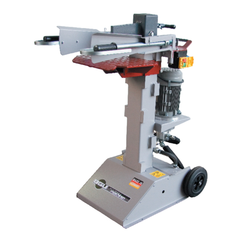
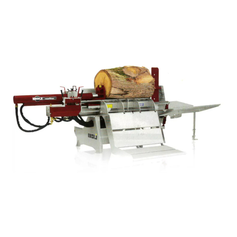
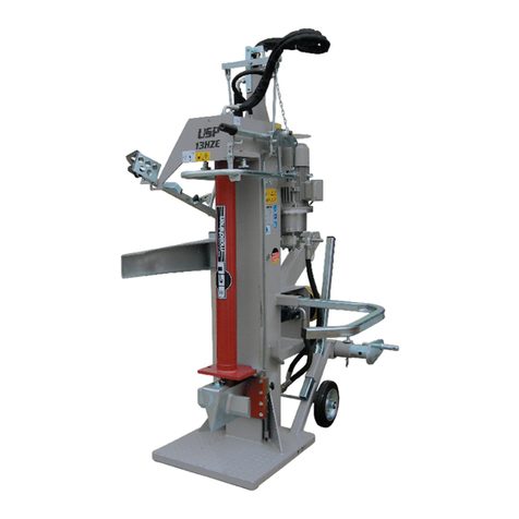
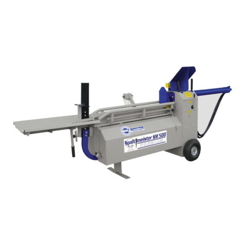
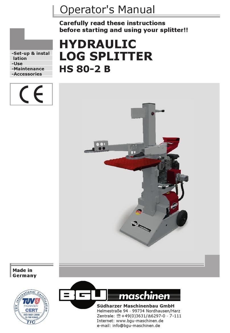
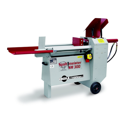
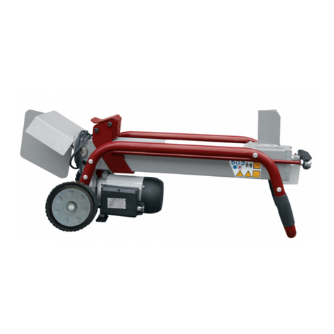
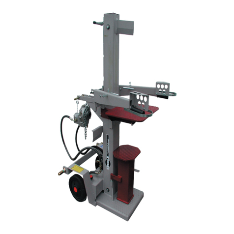
BGU SP 20 HZH/2 User manual

Carefully read these instructions before starting
and using your log splitter!
Südharzer Maschinenbau GmbH
Helmestraße 94 ∙ 99734 Nordhausen/Harz
Zentrale: 03631/6297-0 7-111
Internet: www.bgu-maschinen.de
e-mail: [email protected]
Set-up & installation
Use
Maintenance
Accessories
HYDRAULIC LOG SPLITTERSPALTPROFI
SP 20 HZH/2 - HEH/2 - HZEH/2
We manufactu-
re in Germany
USER‘S MANUAL

2
CONTENTS
1. CONTENTS 3
1.1 About the manual 3
1.2 Delivery and transport claims 3
2. Product overview 5
4. Safety rules 8
4.1 Mandatory application field 9
5. Use 10
5.1 Electrical specifications (SP 20 HEH/2 and SP 20 HZEH/2) 10
5.2 Hydraulic specifications 10
5.3 Attaching the machine to a tractor (SP 20 HEH/2 and SP 20 HZEH/2) 11
5.4 Getting started 11
5.5 Safe operating practices 11
5.6 Operation and start-up rules 12
5.7 Two-hands operation system with automatic two-speed operation valve for shorter splitting cycles 12
6. Transporting the machine 13
6.1 About the transport asset 13
7. Gap cross 14
8. REPAIRS AND MAINTENANCE 15
8.1 Ordinary maintenance 15
8.2 Hydraulic oil specifications 15
8.3 Consumables 16
9. Disabling and scrapping 17
10. Technical specifications 18
10.1 Noise emissions 18
11. Wiring diagram 19
12. Other areas of possible danger 20
12.1 Mechanical dangers 20
12.2 Electric dangers 20
13. Legal warranty 21
14. Extended warranty 21
15. Spare parts list 22
16. EC STATEMENT OF COMPLIANCE 27

3
1. CONTENTS
Dear customer,thank you very much for your trust and preference in
buying this log splitter!
Our log splitter is available in the following two versions:
SP 20 HZH/ 2 PTO
SP 20 HZH/ 2 with electric motor
SP 20 HZEH/2 power combination with electric motor and PTO
1.1 About the manual
Please take time to read this manual and learn to how operate and
maintain the splitter safely. For your easier reading this manual is laid
out in several sections. The sections are progressively numbered 1 th-
rough 16 and listed on the “contents” page. The information, pictures
and technical data in this document reflect current or planned product
features, functions, and characteristics as of the publication date. Be-
cause of on-going product improvements and feature additions, infor-
mation in this document is subject to change without notice.
If you are experiencing a problem or functional trouble on your machi-
ne, please read the “trouble-shooting” section to identify possible cau-
ses and remedies. If the problem or functional trouble is not listed in
the troubleshooting chart contained in this manual,ask our dealer or
our Authorized Service Centre for service.
When you order parts maintenance or repair services, your Authori-
zed Service Centre, your dealer or eventually the manufacturer need
your machine serial number.. These are the numbers that you have
recorded on the product identification label of the manufacturer on the
machine.
1.2 Delivery and transport claims
Upon receiving the splitter at your place, please check for visual ma-
chine damages such as damaged packing or scratched buckled parts.
If so, make a remark on all copies of the delivery bill (including yours)
before signing for acceptance.

4
Also have the truck driver sign al copies of the delivery bill.
Should your shipper or the truck driver refuse to accept your claim,
fully reject delivery of the machine and make sure to inform us (the
manufacturer) immediately. No claims will be taken into account by
the shipper or by the insurance company, if a reservation note is not
made on the delivery bill.
All transport damages must be notified within latest 2 days from de-
livery. Therefore delivery must be collected and inspected within this
term. Later claims will be disregarded. In case of assumed but not vi-
sually clear transport damages make sure to mark the following sen-
tence on the delivery bill: „Reserved delivery due to assumed
transportation damages.“.
Insurance and shipping companies act with extreme caution in case
of transport damages and sometimes refuse to accept responsibility.
Please make sure to provide clear and exhaustive evidence (photos)
of the claimed damages.
Thank you in advance for your help and attention to this matter.
Wir danken für Ihre Mitarbeit.

5
Stand
2. PRODUCT OVERVIEW
Timber lift Part 1
Push-block
Splitter carriage
Splitter wedge
Wood collection
table
Hydraulic cy-
linder
Timber lift Part
Splitte
Splitter wedge
Wood collection
Hydraulic cy-
Timber lift - Part 2

6
1. Machine safety label
„Before setting-up, servicing, maintaining and
cleaning the machine, disengage power and stop
the engine. Lock the tool and secure it against
accidental start!“
This label reminds users of pinched hands danger!
2. Machine safety label
„Read, understand, and follow all instructions in
this manual and on the splitter before starting!“
This label reminds the user to always stand at safe
distance from machine moving parts!
3. Machine safety label „p max 250 bar“
Maximum operating pressure is 250 bar.
4. Machine safety label „Pinched hands danger“
Wear suitable protective gloves! Pinched hands danger in the wedge
hazard area.
5. Manufacturer logo„BGU-Maschinen - Logo“
6. Production label „Production label „Product iden
tifi cation““
This label shows the company details of the manufacturer and the
main machine technical data.
7. Personal protection pictogram
“Wear suitable protective gloves!”
8. Personal protection pictogram
“Wear suitable protective boots!”
3. SAFETY PICTOGRAMS AND WARNING
250

7
9. Personal protection pictogram
“Wear ear plugs and goggles!”
10. Personal protection sign
„Mind these instructions!
11. Machine safety label
„CAUTION: mind for driveshaft revolutions!“
12.
Label „guidances all 10 company hours
to smear „

8
Strictly perform installation, set-up, maintenance, cleaning
and transportation with the motor switched off and all moving
parts firmly secured against accidental operation.
The user shall strictly comply with these operation, set-up, mainte-
nance, repair and trouble-shooting instructions in order to assure
safe operation and avoid damages to the equipment. The owner must
understand these instructions and must allow only persons who un-
derstand these instructions and are familiar with the related risks to
operate the splitter. Moreover we recommend to let the machine be
run only and strictly by trained and skilled staff who must be familiar
with the applicable occupational safety and health administration rules
as well as applicable transportation rules. Incorrect use of the splitter
can cause serious injury or death.
No person under school leaving age (18) should operate this log split-
ter. Those who have reached school leaving age but are below the age
of 16 may operate a log splitter if supervised by a competent person
of 18 years or over.
The machine shall be installed and kept in a suitable location selected
by the customer for safest operation.
The working area around the machine must be kept as clear as pos-
sible from surrounding obstacles. Slippery foundation floors should
be duly treated (do not use saw dust or wood ash for this purpose).
Make sure that the equipment stands on a safe stable foundation. Al-
so make sure to comply with the following provisions.
• Due and proper illumination of the working site must be provided at all times.
• Ensure that a wide but confined area is available around the machine
and assure maximum working freedom.
• A skilled licensed electrician must be asked for any repair of the
electric system.
• Operators must wear steel toe safety shoes and snug-fitting tear-resistant
work cloths.
• No additional customised protections or tools should be provided on
board of the machine, other than the ones designed and supplied by
the manufacturer.
• NEVER leave the machine unattended without prior power disconnection.
Operator‘s hearing protection, safety glasses, safety shoes and
gloves, close fitting cloths and other adequate protection means are
strongly recommended.
4. SAFETY RULES

9
Make sure that all access ways are properly maintained so that wood
can be safely delivered, loaded and shipped.
4.1 Mandatory application field
Log splitters are one-man operation machines. No second operator or
bystanders are allowed on the machine while working.
The machine is strictly designed to split firewood along the wood fibres.
When splitting your logs, be sure that the log is safely laid down in
the special wood carriage by means of the special timber lift.
The manufacturer will consider any other use or application as “misu-
se”, in which case the manufacturer will not be responsible for custo-
mers’ claims or resulting damages.
The user shall strictly comply with these operation, set-up, mainte-
nance, repair and trouble-shooting instructions in order to assure safe
operation and avoid damages to the equipment.
Lack of compliance with these instructions may lead to dange-
rous risks and situations and will void all warranty claims, in
which case the manufacturer will not be responsible for custo-
mers’ claims or resulting damages and/or injuries.

10
5. USE
Fig. 1 Phase changer
5.1 Electrical specifications (SP 20 HEH/2 and SP 20 HZEH/2)
Connect the 400V motor using a 25 m long power cable in a mini-
mum section of 1.5 mm2.
Make sure to connect the neutral return wire of the conductor cord
or the machine won‘t start!
A switch-plug combination outlet provides power supply to the machine.
Before first use, check that the motor rotates in the direction shown
by the arrow on the housing. To do this, quickly switch the motor on
and off. Should rotation be performed in the opposite direction than
shown by the arrow-label on the motor fan, immediately stop the
motor and use a phase inverter (Fig. 1) to change the plugging po-
larity of the conductor cable.
Operating the splitter while the motor turns in the wrong di-
rection may cause major, even permanent damages of the
hydraulic pump!
5.2 Hydraulic specifications
This professional horizontal log splitter has own inbuilt hydraulic sys-
tem with pump and and oil reservoire purposely located at the base
of the main frame. The machine comes from the factory with a first
oil fill. For changing oil in the tank please go to page 14.
Hydraulic oil in the lines may become quite viscous at very
low ambient temperature. In this case, sudden start-up may
damage the hydraulic system of your machine.
In order to protect the system, rather let the splittet run idle (with
no load and no operation) for approximately 15 minutes till the oil in
the lines warms up.
The splitter is hydraulically controlled by means a control valve who-
se fine default-settings are performed by the manufacturer before
delivery. Do not alter these settings, unless prior agreement with
the manufacturer.

11
5.3 Attaching the machine to a tractor (SP 20 HEH/2 and SP 20 HZEH/2)
The machine is equipped with a three-point linkage to fit on the one
available on your tractor. The drive shaft is going to act as linkage and
driving element between the tractor and the splitter and should be
therefore duly mounted and secured by the special pins available on
the machine.
The tube profiles should overlap each other by at least 1/3 of the
overall length (see picture 2).
Make sure to disconnect power (switch the tractor off) before perfor-
ming any work (maintenance or repairs) on the splitter. Strictly use
certified and approved drive shafts and assure strict compliance to the
manufacturer’s instructions for use and assembly. Do not use drive
shafts with damaged broken shields. Never run the machine without
protection shield.
5.4 Getting started
Before starting, inspect the machine for evident, visible damages and
unusual conditions.
Check the state of all hydraulic hoses, fittings and connectors and seal
eventual leaks, if required. Do not check for leaks with your hand.
Leaks can be located by passing a piece of cardboard or wood around
the suspected leak and looking for discoloration. High-pressure fluid
escaping from a very small hole can be almost invisible. Escaping flu-
id under pressure can have sufficient force to penetrate skin, causing
serious injury or even death.
Altering the equipment, or using the equipment in such a way as to
circumvent its safeties. could result in serious or fatal injury.
NEVER operate your processor when it’s in need of repair or in poor
mechanical conditions.
5.5 Safe operating practices
Make sure that the equipment stands on a safe stable foundation.
The working area around the machine must be kept as clear as pos-
sible from surrounding obstacles. Slippery foundation floors should be
duly treated (do not use saw dust or wood ash for this purpose).
Never reach with your hands within the dangerous splitter zo-
ne while the push-block is active and operating!
Fig. 2
Lu=pay length
Shortest length = fully wrapped
Operating length: wrapping over approx. 2/3
of the working length
Max operating length: wrapping over at least
1/3 of the working length

12
Fig. 4
2
1
23
Fig. 3
5.6 Operation and start-up rules
Connect your log splitter to the tractor using a PTO shaft (see para-
graph 5.3) or connect the electric motor to your home power supply
network.
Before starting to work with your log splitter, release the locking bolt
(1) used to secure the log lift in its transport asset. Pull the timber lift
part 1 (Fig. 3) down insert the bottom lock (see figures 3 and 4).
Let the log roll over till it settles on the log lift.
Operate the left hand-lever to adjust the height of the log lift and roll
your timber in the splitter carriage.
Operate the right hand-lever to adjust the height of the 4-ways wedge
depending on your log diameter.
Concurrently press both hand-levers down (towards yourself) to start
the splitting cycle.
If required, engage only one lever to stop the ram at once in its actual
position.
Clear wood or logs rests from the working area and unload wood from
outlet collection table (if full) before setting the log lift down and star-
ting a new cycle.
Let the timber lift down again, to load a new trunk and start a new cycle.
5.7 Two-hands operation system with automatic two-speed operation valve for shorter splitting cycles
The log splitter is equipped with a standard automatic control valve
for two operating modes: fast speed (nearly twice the normal one) at
regular ram force and slow speed at greater ram force. The system
works automatically so that the splitter can perform self-switching on
increased pressure and slower speed every time when a tougher log
requires maximum pressure to split.
Two-hands operation system: Pull both control levers towards you, to
let the ram slide to the wedge. Push both levers down to stroke-end,
to let the ram return to the start position.
WARNING: for no reason you should reach inside the splitting
area on the machine when the ram is sliding!

13
6. TRANSPORTING THE MACHINE
As for any electric tool make sure to disconnect the electrically
operated splitter from the power network before handling, mo-
ving or transporting it away.
The machine can be transported over long distance by means of a trac-
tor. In this case, hang the machine to the three-point attachment and lift
it at least 20 cm above ground.
When travelling on roads, make sure to comply with the national ru-
les of your country. In compliance with the German rules for road tra-
vel (STVO), rear lights are required. Make sure to remove the driveshaft
joint and drive the tractor with caution so to avoid transport damages to
the machine.
The splitter in the transport asset with up-folded timber filt and outlet
collection table has a very compact width of 2700 mm. This makes tra-
velling on narrow roads or through the woods easier and possible.
6.1 About the transport asset
To prepare the machine for road transportation the following steps
should be followed:
Manually push the ram back to retract it within applicable road profile.
To do so, follow the procedure below:
• Release the locking bolt (4), release the star-knob (5) and remove
the stop plate (6). (see Fig. 5)
6
5
4
Fig. 5

14
• Manually muscle the ram (7) into transport position (see Fig. 6 and 7)
• Secure the ram using the star-knob (5) and install the stop plate (6)
(see Figure 8)
7. GAP CROSS
• Our Spalter are equipped serially with the 4-th gap cross.
• As a Zubehör* the 6-th gap cross is available in star form (Abb.9)
• Art.-Nr. 94747 (for SP 20-and 30 models SP)
* Accessories are no basic equipment, if requested, however, availably and there
fore additional costs.
Fig. 8
Fig. 6
Fig. 7
7
7
5
6
Fig. 9

15
Make sure that the machine is fully disconnected and all moving parts
are secured before performing any maintenance/cleaning work on the
machine. In the event of any malfunctioning, switch the machine off be-
fore trouble-shooting.
8.1 Ordinary maintenance
Make maintenance a regular part of daily operation. The daily mainte-
nance routine needs to include:
• Cleaning of the machine and clearing of all parts from residual wood
debris, chips, dust, bark pieces and eventual other waste
• Greasing of the sliding pads
• Hydraulic oil level check and (in case of leakage) hydraulic hose and
fittings check-up to detect eventual oil leaks
• Lubrication of all moving parts
8.2 Hydraulic oil specifications
Periodically check the oil level inside the hydraulic oil tank. When do-
ing so, accurately avoid contaminating the tank with dirt, wood chips,
sow dust etc...
Make sure that the splitter never runs without oil or with a low oil le-
vel. When this happens, air is likely to reach inside the hydraulic loop.
Failure to maintain due oil level may cause poor running and irregular
splitter operation (very rough, jerky motions) as well as major pump
damages.
Please schedule your first oil change after approximately 50 operation
hours. Later oil changes and filter cartridge replacements should be
done after each 3000 and 5000 operation hours.
Recommended oil types:
DEA HD B 46, Shell Tellus 10-46, Esso Nuto H 46
Periodically check the oil level inside the gearbox and provide a com-
plete change at least once a year.
Gearbox oil capacity: approx. 0,6 L
Recommended gear oil type Any oil with viscosity class CLP/CC 150
(ISO150) (SAE 90)
8. REPAIRS AND MAINTENANCE

16
To perform an oil change the following steps should be followed:
Make sure that the splitter in fully disconnected from its po-
wer source!
• Remove the drain plug located on the bottom tank side and place
a sealed oil collection container underneath it (oil disposal contai
ners should be of at least 60 l capacity)
• After draining the oil out, fit the plug back on and clean the suction filter
• Remove the filler cap on the tank and fill approximately 60 l oil
in while you keep checking the oil level through the oil sight glass
• After refilling the tank with new oil, let the splitter cycle three or
four times and let the air blow out of the hydraulic loop before clo
sing the cap. Let all air bleed out of the hydraulic system.
Your log splitter is now ready to start again.
All hose connections must be always tight and sealed.
Used oil is very polluting and should be disposed in accordance
with the local rules!
8.3 Consumables
Wearing parts are excluded from the guarantee claim.
• Copper pads (Code No. 24648)
• Hydraulic hoses (please replace them every 4-5 years)
• Hydraulic oil (Code No.96092)and Return filter cartridge (Code
No.5611)(replace approx. every 3000-5000 operation hours)

17
When the splitter is fully obsolete and cannot be of any longer use, it
should be duly dismounted ahead of discarding. Certain components
need deactivation and dismantling in order to assure that no further
use is made by other parties and that no worn out parts are recycled
for other applications.
During dismantle be alert for possible recyclable materials and com-
ponents that belong to differentiated waste collection procedures ap-
plicable in your country.
The manufacturer is not liable and undertakes no responsibility for
personal injuries or damages that may result from the recycling of
worn outmachine parts and eventual re-use in other applications diffe-
rent than originally stated in this manual.
Dismantling procedure:
Take good note please: each and every dismantling task must beper-
formed by authorized service centres or trained skilled staff only!
● Lock and clamp all moving machine parts and pull the machine
down into single components
● Deliver each single component only to authorized waste manage
ment facilities
● Drain oil and fuel out of respective tanks and lines before disposal of
the machine
● Remove rubber and plastic parts from the machine that must be se
parately disposed of.
Deactivated, clamped moving/driving parts and components are of no
further risk and danger.
Electric components must be separately disposed to avoid substantial
environmental threat. In the event of fire on the electric deployment
system of the machine, use of an explosion-proof extinguish system is
required (for example powder fire extinguishers).
9. DISABLING AND SCRAPPING

18
Technical data SP 20 Unit of
measure-
ment
HZH/-2 HEH-2 HZEH/-2
Splitting force t 20 20 20
Min. log capacity mm 200 200 200
Max log capacity mm 1100 1100 1100
Max operating pressure bar 250/160 250/160 250/160
Tractor power requirements KW/PS 30/45 30/45
Tank capacity l 80 80 80
Max number of driveshaft RPM 420 420
Domestic overload safety A 1 x 32 fuses 1 x 32 fuses
Motor power kW 7,5 7,5
Motor speed RPM 1450 1450
Splitter height (Transport asset) mm 1550 1550 1550
Splitter length (Transport asset) mm 2700 2700 2700
Splitter width (Transport asset) mm 1400 1400 1400
10. TECHNICAL SPECIFICATIONS
* Please account for ± 10% splitting power rates.
10.1 Noise emissions
Noise emissions were measured in accordance with the European di-
rectives for the measurement of noise emissions on the workplace.
The measurement was performed by external authorized certification
bodies in compliance with the applicable standards based on applica-
ble rules for agricultural and forestry equipment. The detected noise
level was:
LpA = 80 dB(A) and 90 dba at max loading conditions

19
11. WIRING DIAGRAM
BEWARE: only let expert skilled staff do electric repair/mainte-
nance works!
As for all electric tools and equipment we strongly recommend use a por-
table residual current device (PRCD), unless you already have in your
house a residual current device (RCD) set for max tripping current of 0.03
Amp assuring safety and protection.
Component list:
1. Metal housing K3000
2. Safety Ucc 400V 7.5 KW
3. Overload protection 18.0A x 0.58 = 10.5A(11)
4. Delta-start switch
5. Motor

20
12. OTHER AREAS OF POSSIBLE DANGER
12.1 Mechanical dangers
Possible dangers related to machine moving parts (wedge) are mi-
nimized by means of the two-hands operating system. The machine
won’t start, if any of the control levers is permanently held down in its
operating position.
DO NOT EVER ATTEMPT to remove or by-pass the two-hands control!
Danger: operating the splitter without the safety two-hands control
will increase your risk of having your hands pinched during the split-
ting cycle.
Do not remove any other safety and protection device from the ma-
chine.
WARNING: splitting without due safety devices might result into se-
rious injures to the operator or the other person around the workplace
12.2 Electric dangers
All machine parts staying under voltage are duly insulated or sealed
inside a fixed casing to avoid accidental contact. For safety reasons all
fixed casings can be only removed using special tools and equipment.
WARNING: removing a fixed protection casing when the machine is
running or without having priory cut the power off, may result into
major danger of electrical shock!
This manual suits for next models
2
Table of contents
Other BGU Log Splitter manuals
Popular Log Splitter manuals by other brands
Scheppach
Scheppach HL810 Translation from the original instruction manual
Farmi Forest
Farmi Forest Mastersplit WP30 Operating, Maintenance and Spare Parts Manual

Toro
Toro 22618 Operator's manual

AL-KO
AL-KO KHS 3704 operating instructions

North Star
North Star M1108W owner's manual

Craftsman
Craftsman 675 Series Operator's manual
power King
power King PK0322 Owner's Manual and Operating Instructions
YTL
YTL 23316 Instructions and Assembly

YARDMAX
YARDMAX YUT032 Operator's manual
ATIKA
ATIKA ASP 6 L-2 Assembly and operating instruction sheet

Brave
Brave VH9934 Owner/operator and safety manual

Mountfield
Mountfield Levita 4T owner's manual
