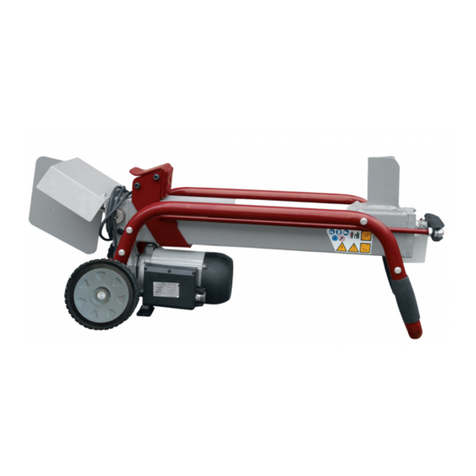
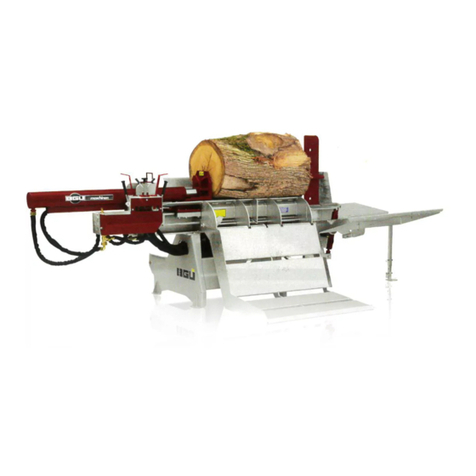
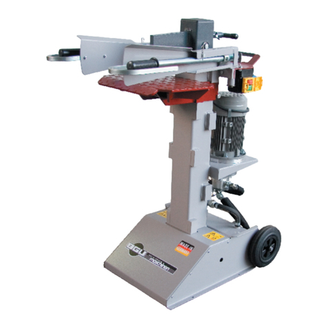
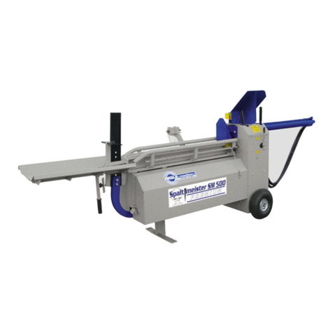
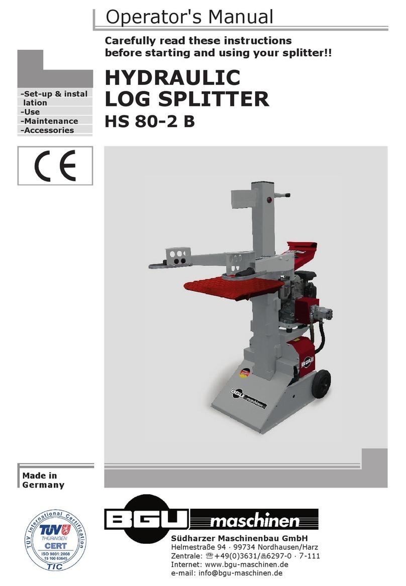
BGU SM 300 User guide

ORIGINAL INSTRUCTION MANUAL
Carefully read these instructions
before starting and using your splitter!
Südharzer Maschinenbau GmbH
Helmestraße 94 ∙ 99734 Nordhausen/Harz
Zentrale: +49(0)3631/6297-0 ∙ -111
Internet: www.bgu-maschinen.de
e-mail: [email protected]
- Set-up &
installation
- Use
- Maintenance
- Accessories
SPALTMEISTER
SM 300
We manufactu-
re in Germany

2
CONTENTS
1. Introduction 3
1.1 About the manual 3
1.2 Delivery and transport claims 3
2. Product overview
5
3. Safety pictograms and warning labels 6
4. Safety 8
4.1 Mandatory application field 9
5. Operation 10
5.1 Splitter set-up ready for use 10
5.2 Electric specifications 10
5.3 Hydraulic specifications 10
5.4 Initial check-up 11
5.5 Start-up 11
5.6 Operating safety 12
5.7 Adjusting the ram travel 12
5.8 Extension table 12
5.10 Operation 13
5.11 Clearing logs jammed on the wedge 13
6. Handling and transportation 14
15
7. Splitting wedge and cleaving wedge 15
8. Repairs and maintenance 16
8.1 Ordinary periodic maintenance 16
8.2 Hydraulic oil 16
8.3 Sliding pads in the log carriage 17
8.4 Consumables 17
9. Disposal 18
10. Technical data 19
9.1 Noise level and emissions 19
11. Wiring diagram 20
12. Other areas of possible danger 22
2.1 Mechanical dangers 22
2.2 Electrical dangers 22
13. Legal warranty 22
14. Extended warranty 23
15. Spare parts for SM 300 24
15.1 How to order spare parts 30
16. EC Statement of compliance 31

3
1. INTRODUCTION
Dear customer, thank you very much for your trust and preference in
choosing our equipment and joining the number of our best customers
in the world. We are confident that our equipment will be up to all your
expectations and assure you a long lasting quality and performance.
Our range of hydraulic log splitters includes various different models
of different splitting force.
SM 300, 400 V, Splitting force 6 t
SM 300, 230 V, Splitting force 6 t
All splitters are equipped with mechanical two-hands safety control.
1.1 About the manual
Please take time to read this manual and learn to how operate and maintain
the splitter safely. For your easier reading this manual is laid out in several
sections. The sections are progressively numbered 1 through 16 and listed on
the “content” page. The information, pictures and technical data in this do-
cument reflect current or planned product features, functions, and characte-
ristics as of the publication date. Because of on-going product improvements
and feature additions, information in this document is subject to change wi-
thout notice. If you are experiencing a problem or a functional trouble on
your machine, please read the “trouble-shooting” section to identify possible
causes and remedies. If the problem or functional trouble is not listed in the
troubleshooting chart contained in this manual, ask your Authorized Service
Centre for service. When you have checked all the possible causes listed and
you are still experiencing the problem, ask your Authorized Service Centre
for help. When you order parts maintenance or repair services, your Autho-
rized Service Centre, your dealer or eventually the manufacturer need your
machine serial number and engine serial number. These are the numbers
that you have recorded on the product identification label of the manufactu-
rer on the machine.
1.2 Delivery and transport claims
Upon delivery of the machine please check for visual machine damages
such as damaged packing or scratched buckled parts. If so, make a re-
mark on all copies of the delivery bill before signing for acceptance.
Also have the truck driver sign al copies of the delivery bill.

4
Should your shipper or the truck driver refuse to accept your claim,
fully reject delivery and make sure to inform us (the manufacturer)
immediately. No claims shall be taken into account by the shipper or
by the insurance company, if a reservation note is not made on the
delivery bill.
All transport damages must be notified within latest 2 days from de-
livery. Therefore delivery must be collected and inspected within this
term. Later claims shall be disregarded. In case of assumed but not
visually clear transport damages make sure to mark the following
sentence on the delivery bill: „Reserved delivery due to assumed
transportation damages“.
Insurance and shipping companies act with extreme caution in case
of transport damages and sometimes refuse to accept responsibility.
Please make sure to provide clear and exhaustive evidence (photos)
of the claimed damages.
Thank you in advance for your help and attention to this matter.

5
2. PRODUCT OVERVIEW
Hydraulic ram
Hand guard
Control lever
Extension table
Leg with grip handle Casing
Log carriage
Push-plate
Wheels
On/Off switch
Ram stop

6
3. SAFETY SIGNS AND WARNING LABELS
p max 220
1. Machine safety label
„before setting-up, servicing, maintaining and
cleaning the machine, disengage power and stop
the engine. Lock the tool and secure it against ac-
cidental start.“
This safety label reminds users of the general safety rules.
2. Machine safety label
„Read, understand, and follow all instructions in
this manual and on the splitter before starting!“
This safety label reminds the user about the importance of reading
and understanding the instructions of the manufacturer and getting
familiar with the machine before you fi rst use it.
3. Operation safety label
„One-man operation only!“
Possible dangers can arise from moving parts on the machine.
The machine is to be strictly operated by one man at a time only.
4. Machine safety label “max pressure 220 bar“
Maximum operating pressure is 220 bars.
5. Operation safety label “Pinched hands danger!“
Keep your hands off all moving machine parts! Pinched hands danger.
6. Operation safety label „Check motor revolutions!“
Avoid dangers and check motor revolutions upon starting when
using a 400V motor..
7. Machine safety label „Direction arrow“
The motor must be turning in the same direction as shown by this ar-
row.
8. Operation safety label „Lubricate all guides and
sliding parts every 10 operation hours!

7
9. „BGU-Maschinen” manufacturer’s logo
10. „Product Identification label“
This label shows the company details of the manufacturer
and the main technical data of the machine.
11. Personal protection pictogram
“Wear suitable protective gloves!”
12. Personal protection pictogram
“Wear suitable protective boots!”
13. Personal protection pictogram
„Wear ear plugs and goggles“
14. Personal protection sign:
„Read before use and mind these instructions!“
15. Machine safety label
„Moving parts“
16. Safety-alert symbol
Read and recognize safety information. Be alert to
the potential for personal injury when you see this safety-
alert symbol!

8
Strictly perform installation, set-up, maintenance, cleaning and
transportation with the motor switched off and the blade firmly
secured against accidental operation.Immediately disconnect
power off the machine in case of any eventual fault or trouble.
The user shall strictly comply with these operation, set-up, mainte-
nance, repair and trouble-shooting instructions in order to assure safe
operation and no damages to the equipment. Moreover we recom-
mend to let the machine be run only and strictly by trained and skilled
staff who must be familiar with the applicable occupational safety and
health administration rules as well as applicable transportation rules.
Incorrect use of the saw can cause serious injury or death.
No person under school leaving age should operate a circular saw. Those
who have reached school leaving age but are below the age of 18 may ope-
rate a circular saw if supervised by a competent person of 18 years or over.
The machine shall be installed and kept in a suitable location selected
by the customer for safest operation. The working area around the
machine must be kept as clear as pos-sible from surrounding obstac-
les and slippery foundation floors should be duly treated (do not use
saw dust or wood ash for this purpose). Make sure that the equipment
stands on a safe stable foundation.
• Due and proper illumination of the working site is provided at all times
• A wide but confi ned area is available around the machine to stop
access of unskilled personnel during operation and still assure maxi-
mum working freedom
• A skilled electrician is asked for any repair on the electric system
• All operators wear steel toe safety shoes and snug-fitting tear-re-
sistant work cloths
• No additional customised protections or tools are provided on board of the
machine, other than the ones designed and supplied by the manufacturer
• Never leave the splitter unattended with its motor on
Always assure compliance with safety, protection and accident pre-
vention rules as well as general road andtraffi c rules in the country
of use.
Operators should always wear personal protection cloths including
steel-toed safety shoes, snug-fi tting tear-resistant work cloths, safe-
ty gloves earplugs and safety goggles. Site must be free of slippery
surfaces and tripping obstacles. Make su-re that all access ways are
properly maintained so that wood can be safely delivered, loaded and
shipped.
4. SAFETY

9
4.1 Mandatory application fi eld
Log splitters are one-man operation machines only. Never allow mo-
re than one person approach and work on the machine at the same
time. The model “SM 300” is conceived for splitting logs for firewood
preparation only. BEWARE: no cross-grain splitting is permitted. Al-
ways split grain-wise.
When placing the log on the log splitter make sure that the chunk
rests entirely and safely on the log carriage. Any other use or splitting
method is considered by the manufacturer as “misuse”. In case of mi-
suse the manufacturer will not be liable for any injuries or damages
and the operator will be held entirely responsible.
Please make sure to comply with these set-up, operation and mainte-
nance/repair instructions in order to avoid happening of any injury or
dangerous condition.
Misuse will completely void your warranty. The manufacturer
accepts no liability for personal injuries and damages to other
equipment caused by misusing the machine.

10
5. OPERATION
Fig. 1
5.1 Splitter set-up
For optimized transport dimensions and more effective handling, the
unit is shipped by the manufacturer with the ram fully retracted over
the log carriage. To set the unit ready for splitting you first need some
minor setup work. Bolt the cylinder flange firmly on the steel casing
(Figure 1).
To do this, simply undo the fixation screws on the casing and pull
them out of their threaded seating. Shift the ram backward to make
the flange reach tightly against the steel casing.
Now, screw the flange of the cylinder using the two hex screws on the
casing.
Whilst tightening the screws make sure that the ram lay perfectly ho-
rizontal. WARNING: a skewed, offset ram will cause the push plate to
apply excessive strain on the piston rod ending up into leaks and even
permanent damage of the cylinder gaskets.
5.2 Electric specifications
Connect the 400V motor using a 25 m long power cable in a minimum
section of 1.5 mm2.
Make sure to connect the neutral return wire of the conductor cord or
the machine won‘t start!
If you are using an AC (230V motor) splitter version, the power cord
section may not exceed 2,5mm² (standard power cord denomination: 3
x 2.5). Power-up is performed by means of a switch/plug combination.
In case of splitters powered by a 400V motor, first check that the mo-
tor rotates in the direction shown by the arrow on the housing. To do
this, quickly switch the motor on and off. Should rotation be perfor-
med in the opposite direction than shown by the arrow-label on the
motor fan, immediately stop the motor and use a phase inverter (Fig.
1) to change the plugging polarity of the conductor cable.
Operating the splitter while the motor turns in the wrong di-
rection may cause major, even permanent damages of the
hydraulic pump!
5.3 Hydraulic specifications
The splitter has an independent hydraulic plant with tank and pump.
The hydraulic tank is located in the floor stand of the machine and is
always supplied by the manufacturer with a first hydraulic oil fill.

11
Fig. 2
1
BEWARE: an excessively backwards leaning position of the splitter during transportati-
on may result into oil leakage from the oil plug. See page 16 for oil change instructions.
At low ambient temperature the oil in the hydraulic circuit will thicken.
In this case, it is recommended to avoid sudden start-up (splitting wi-
thout warming the motor up) that could result into damages and trou-
ble of the hydraulic system.To assure trouble free operation of the hy-
draulic system at low ambient temperature, let the motor run idle and
cycle the unit several times till the oil in the hydraulic loop warms up.
Setting of the main control valve is done in the factory before ship-
ping. The unit comes to you ready for service so that no other adjust-
ment/installation work is required.
5.4 Initial check-up
The log splitter is equipped with safety two-hands mechanical controls
(Fig. 2) designed for the operator to keep both hands free from dan-
ger and from infringing the moving ram zone during the entire split-
ting cycle.
It is strongly recommended to check the operation of the two-
hands control every time before a new use.
To do so, engage both hand levers (1) and hold them down at the sa-
me time to let the push-plate advance all the way to the wedge.
If your system is duly set, the push-plate stops upon releasing of just
one of the two levers while the ram stops its back/forth stroke at once.
On the other hand, the ram must recommence its backwards travel to
the initial start position as soon as the other lever is also released.
Make sure that the ram performs no travel when operating only one
single lever. Check that both levers spring back into their normal posi-
tion when the hand pressure is released.
5.5 Start-up
Before fi rst use, make sure that the log splitter is in good conditions
and that there are no visual damages.
Check all hydraulic hoses, fi ttings and couplings and to detect and re-
pair eventual oil leaks.
Make sure that all safeties and protections are duly assembled on the
machine. Do not attempt to remove or by-pass these safeties!
Should any trouble or unusual behaviour be detected, do not
start splitting wood until these have been fi xed.

12
Fig. 3
5
4
5.6 Operating safety
Choose a flat, dry, and solid location to operate your splitter.
Make sure that the area is free of slippery surfaces and objects to trip
over. Slippery and icy floor conditions must be duly treated to ensure
solid standing conditions.
This unit is strictly one-man operation.
Never reach with your hands at pinch points where they can
get caught by the travelling push-plate!
5.7 Adjusting the ram travel
The ram travel is factory set to the maximum log capacity before ship-
ment.
As you start the motor, the ram slides automatically back to the
maximum travel stroke.
Should your chunks be much shorter than your capacity on the ma-
chine, it is possible to adjust the ram stroke accordingly. Stepless ram
stroke (4) adjustment is possible at all times. (Fig. 3)
Ram stroke (4) adjustment procedure:
Let the ram with the push-plate slide to the desired stroke length and
shut the motor off. When you do this, make sure to keep engaging
one of the control levers (1 in fig. 2) in order to prevent the ram from
returning back to its initial position.
Now release the star-knob screw (5) on the length-stop rod underne-
ath the log carriage and move it to the desired position. To lock the
length stop in the new position, tighten the star-knob screw (5).
The ram travel is reduced by an equivalent stroke length as the extent
of shifting to the left of the length-stop rod length.
Now, the push-plate (4) will no longer travel to its end position but
rather stop at the new setting of the length-stop rod.
To regain the original full-stroke travel, release the star knob and
let the push-plate slide back to its initial position. Make sure to re-
tighten the star knob before operating the splitter again.
5.8 Extension table
The splitter comes with a special steel extension table.
The extension attaches to the carriage on the wedge side and is desi-
gned to collect the wood sticks as they come off the machine through
the wedge.

13
6
Fig. 4
The extension table attaches quickly and easily to the carriage without
having to use any special tool or equipment.
Insert the central lug into the special slot in the front bracket of the
cover plate. Now lift the extension table slightly up and keep settling
it until the canted lugs are hooked up in the back of the mounting pla-
tes on the beam.
To remove the extension table (6), just slightly tip it over to release it.
5.9 Operation
Switch the splitter on. Load a chunk centrally on the log-carriage.
Now push both handles down at the same time to start the cycle and
engage the push-plate that will immediately start advancing to the wedge.
DO NOT RELEASE THE CONTROL HANDLES UNTIL THE CYCLE IS
COMPLETELY OVER AND THE LOG IS SPLIT.
Should any emergency arise and stopping be required, simply set
both control handles free from your grip. When doing this, the ram
will immediately travel all the way back to start position.
As soon as the log is completely split, release both control handles and let
the push-plate travel back to start position and be ready for a new cycle.
As soon as the log is completely split, release both control handles
and let the push-plate travel back to start position and be ready for a
new cycle after clearing the wood sticks from the extension table.
Do not attempt to catch the split wood or remove wood sticks from
the extension table by hand until the cylinder rod stops at its maxi-
mum travel position. Clear the table and remove chips and wood de-
bris from the machine before starting a new cycle.
When loading chunks, make sure that logs sits central and firmly on
the log carriage. Do not split wood chunks with lots of branches, first
clean it and remove all branches. DANGER: crooked trunk pieces with
green/dry branches may burst under wedge pressure!
Make sure to shut the motor off before leaving the area at work end.
5.10 Clearing logs sticking to the wedge
Depending on the type of wood being split, a log may not always
break into two pieces and clear off the wedge. If a log sticks to the
wedge, let the push-plate slide all the way back and switch the splitter
off. Now carefully remove or hammer the log off the wedge.

14
Before handling, moving or transporting the splitter make sure to cut the
power off (unplug the machine). This machine is conceived for very er-
gonomic easy handling thanks to the special wheel arrangement in the
rear bottom part of the machine (fi g. 5).
Dismount the extension table (6) Fig. 5. 2. To do this, fasten the hand-
le (7) with one hand, pull the splitter up and start hauling it away on its
back wheels.
For space-saving during storage and transportation the ram must be ful-
ly retracted over the carriage.
To retract the cylinder in trasport asset, fi rst release both hex nuts
(SW 19) of the fl ange and then shift the ram all the way to the edge
on the opposite side of the splitter.
To set the splitter ready to work again, make sure to screw and secure
the cylinder back to the casing (see 5.1 “Splitter setup”).
6. HANDLING AND TRANSPORTATION
Fig. 5
7
(6)

15
7. SPLITTING WEDGE AND
CLEAVING WEDGE
Fig. 7
Abb. 6
8
9
On request, the log splitter can be factory equipped with a 4-ways
wedge (Pos. 8, Fig. 6) and/or a splay wedge (Pos. 9, Fig. 7).
The 4-ways wedge (8) is designed for splitting each log in 4 sticks in
one cycle.
The splay wedge (9) can be used for cleaving big, hardwood logs and
facilitates breaking through the log.
4-ways wedge and splay wedge are simply slipped on the permanent
wedge and secured by tightening of the star knob screw.
BEFORE STARTING THE CYCLE make sure that the 4-ways/
cleaving wedge or extension wedge is fully slipped-on the per-
manent wedge and secured in position!
BEFORE STARTING THE CYCLE make sure that wedge is fully slipped-
on the permanent wedge and secured in position with the blade wings
facing the operator side (Fig. 7). Do not work with a loosened wedge
to avoid falling off during splitting! This is a very UNSAFE method and
could result in major injuries to the operator and permanent machine
damages.
Preferably refrain from using a 4-ways wedge on hard, heavy woods
(for example flowering trees and beech wood) that are going to op-
pose a stronger resistance to the wedge causing the relief valve to
actuate the hydraulic system leading to a more likely jamming of the
wood.
This accessory is not included in the price of the standard machine.

16
8. REPAIRS AND
MAINTENANCE
Fig. 8
10
Make sure that the machine is fully disconnected and all mo-
ving parts are secured before performing any maintenance/re-
pair work on the machine. In the event of any malfunctioning,
switch the machine off before trouble-shooting.
8.1 Ordinary periodic maintenance
Make maintenance a regular part of daily operation. The daily mainte-
nance routine needs to include:
• Cleaning of the machine and clearing of all parts from residual wood
debris, chips, dust, bark pieces and eventual other waste.
• Greasing of the piston rod pads inside the splitter slider.
• Hydraulic oil check and (in case of leakage) hydraulic hose and fit-
tings check-up to detect eventual oil leaks. To check the oil level re-
move the rear cover first.
• Lubrication of all moving parts.
8.2 About hydraulic oil
Periodically check the oil level inside the hydraulic oil tank. When doing so,
accurately avoid contaminating the tank with dirt, wood chips, dust etc...
Make sure that the splitter never runs without oil or with a low oil le-
vel. When this happens, air is likely to reach inside the hydraulic loop.
Failure to maintain due oil level may cause poor running and irregular
splitter operation (very rough, back/forth or up/down motions) as well
as major pump damages.
Please schedule your first oil change after approximately 50 operation
hours and later ones after each 3000-5000 operation hours.
The oil drain plug is located on the bottom tank side while the fillercap
(10) is on the upper right hand side of the tank (see fig. 8).
Recommended oil types:
DEA HD B 46, Shell Tellus 10-46, Esso Nuto H 46
When changing the oil, never let used oil drop down on the ground,
rather collect whole of it in a sealed container for due disposal. Oil
disposal containers should be of at least 9 l capacity. If you are using
smaller containers, make sure to drain the tank in more than one
round to avoid spilling old oil out on the ground.
Used oil is very polluting and should be disposed in accordance
with local rules!

17
After refilling the tank with new oil, let the splitter cycle three or four ti-
mes and let the air blow out of the hydraulic loop before closing the cap.
8.3 Sliding pads
Should irregular noisy knocks be heard while the ram is shifting back
and forth, grease the plastic sliding pads located inside the log carria-
ge. Preferably use commercial grease available in your country.
The noisy knocks should disappear after greasing.
Should you detect an unusually larger gap between the push-block
and and the sliding pads (see section 8.4), sliding pads are likely to
be worn out. If so replace them with brand new ones.
To do so, first release both hex nuts (SW 19) on the cylinder flange
(see figure 9).
Now shift the cylinder half way through the log carriage, undo all 4
push-plate bolts and flip the flange off from one side (figure 10) and
take the pad out.
Slightly raise the push-plate up, remove the old pads from underne-
ath the push-block and slip new ones in.(see section 8.4) .
Now screw the pads back to the push-plate, shift the push-block back
against the steel casing and finally screw the cylinder flange to the
steel casing again.
8.4 Consumables
Lower sliding pad (Part no. 53058)
Hydraulic hoses (replace every 4-5 years)
Hydraulic oil and filter cartridge (replace every 3000-5000 operation
hours)
Abb. 9
Abb. 10

18
When the splitter is fully obsolete and cannot be of any longer use, it
should be duly dismounted ahead of discarding. Certain components
need deactivation and dismantling in order to assure that no further
use is made by other parties and that no worn out parts are recycled
for other applications.
During dismantle be alert for possible recyclable materials and com-
ponents that belong to differentiated waste collection procedures ap-
plicable in your country.
The manufacturer is not liable and undertakes no responsibility for
personal injuries or damages that may result from the recycling of
worn out machine parts for eventual re-use in other applications diffe-
rent than originally stated in this manual.
Dismantling procedure:
Take good note please: each and every dismantling task must be per-
formed by authorized service centres or trained skilled staff only!
• Lock and clamp all moving machine parts before pulling the machine
down into single components
• Deliver each single component only to authorized waste manage-
ment facilities
• Drain oil and fuel out of respective tanks and lines before disposal of
the machine
• Remove rubber and plastic parts from the machine that must be se-
parately disposed of.
Deactivated, clamped moving/driving parts and components are of no
further risk and danger.
Electric components must be separately disposed to avoid substantial
environmental threat.
In the event of the fire on the electric deployment system of the ma-
chine, use of an explosion-proof extinguish system is required (for ex-
ample powder fire extinguishers).
9. DISPOSAL

19
Technical data Unit of mea-
surement
SM 300
400 V
SM 300
230 V
Max log capacity (length) mm 570 570
Min. log diameter mm 70 70
Max. log diameter mm 300 300
Slitting force* t 6 6
Max. operating pressure bar 220 190
Motor power P1 kW 3,0 2,2
Rated voltage V 400 3N/PE/AC2 230 2N/PE/AC2
Domestic overload safety A 16 fuses 16 fuses
Out-to-out length in transport asset mm 1200 1200
Out-to-out length w. extension table mm 1520 1520
Height mm 1200 1200
Width mm 600 600
Weight kg 138 138
Oil tank capacity l 9,0 9,0
10. TECHNICAL DATA
* The actual splitting force may vary ± 10% of the nominal rating.
10.1 Noise level and emissions
Noise emissions were measured in accordance with the European di-
rectives for the measurement of noise emissions on the workplace.
The measurement was performed by external authorized certifi cation
bodies in compliance with the applicable standards based on applica-
ble rules for agricultural and forestry equipment.
Noise levels were detected and measured 1600mm high above the
machine and 1000mm away in front of it. The detected noise level
was:
LpA = 79 dB(A).

20
11. WIRING DIAGRAM
BEWARE: only let expert skilled staff do electric repair/mainte-
nance works!
As for all electric tools and equipment we strongly recommend use a
portable residual current device (PRCD), unless you already have a
residual current device (RCD) in your house assuring safety and pro-
tection up to max 0.03A nominal fault current.
400 V
version
Components:
1. Box K900
2. Overload safety switch 5.0A
3. KB-04 400V
4. Motor
Table of contents
Other BGU Log Splitter manuals
Popular Log Splitter manuals by other brands

Scheppach
Scheppach HL800VARIO Translation from the original instruction manual
Scheppach
Scheppach HL1800GM Translation from the original instruction manual

Mr.Paldu
Mr.Paldu Horizontalspalter 550 operating instructions
Scheppach
Scheppach HL1600 Translation of original instruction manual
Homelite
Homelite UT49103 Operator's manual
Craftsman
Craftsman 247.77640 Operator's manual
