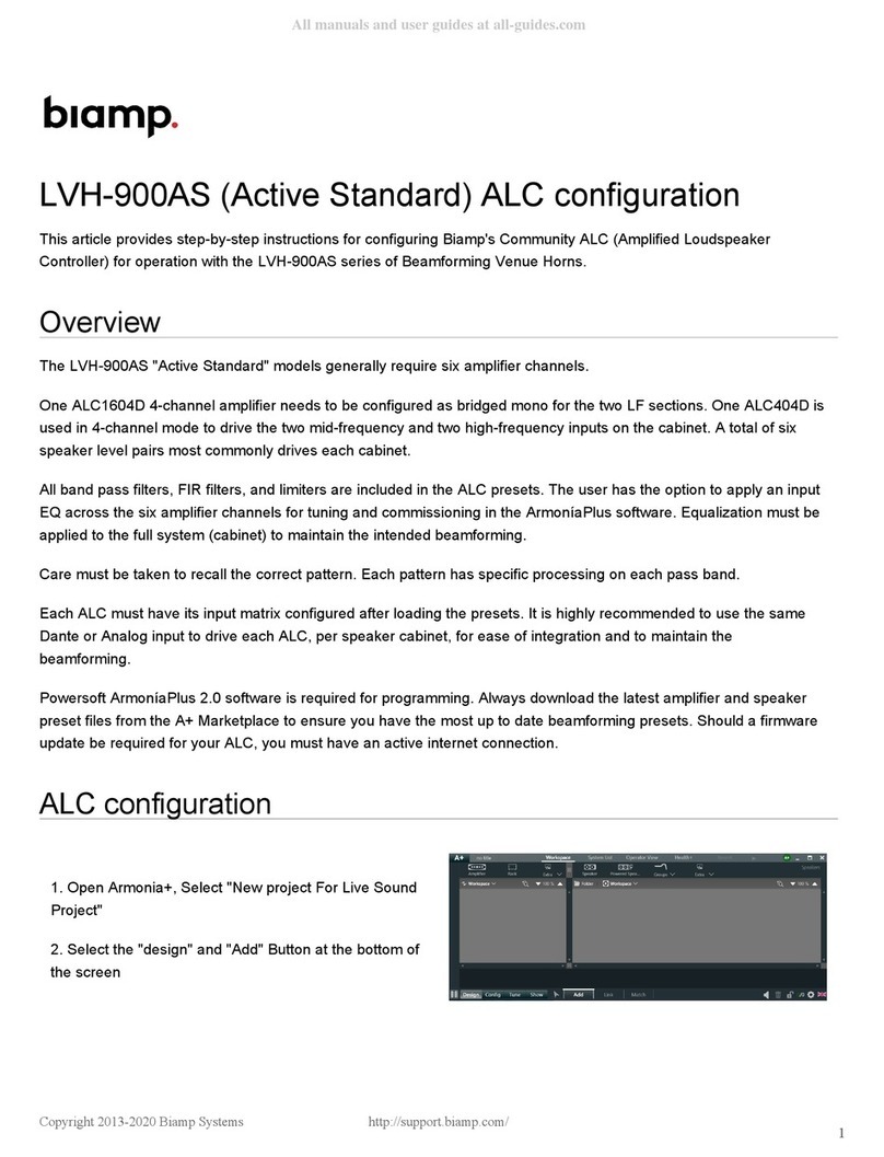
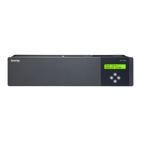
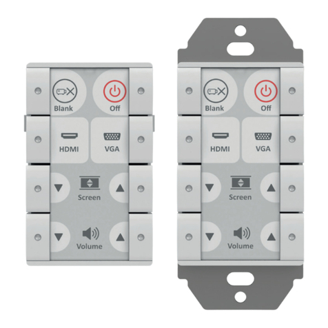
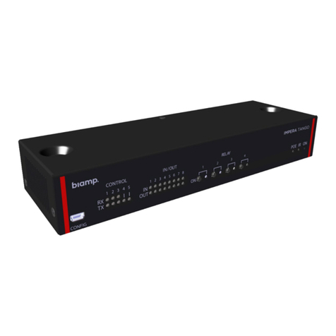
Biamp IMPERA ALFA II User manual

A: 9300 S.W. Gemini Drive Beaverton, OR 97008 USA
T: +1 503.641.7287
W: www.biamp.com
1
INSTALLATION MANUAL
IMPERA ALFA II
000.0000.000
WHAT IS IN THE BOX?
The box contain the following items:
• 1 x Impera - ALFA II
• Power cable
• Cable relief bracket
• Cable relief cover
• Phoenix connectors
• Screws
• Cable binders
• Installation manual
IMPORTANT SAFETY INSTRUCTIONS
Caution:
Read these instructions:
Read and understand all safety and operating instructions before using the equipment.
Keep these Instructions:
The safety instructions should be kept for future reference.
Heed all Warnings:
Follow all warnings and instructions marked on the equipment or in the user information.
Avoid Attachments:
Do not use tools or attachments that are not recommended, because they may be hazardous.
Warning!:
• This equipment should be operated only from the included power supply.
• To remove power from the equipment safely, remove all power cords from the rear of the equipment, or
the desktop power module (if detachable), or from the power source receptacle (wall plug).
• Power cords should be routed so that they are not likely to be stepped on or pinched by items placed
upon or against them.
• Do not defeat the safety purpose of a polarized or grounding-type plug. A polarized plug has two
blades with one wider than the other. A grounding-type plug has two blades and a third grounding
prong. The wide blade or the third prong is provided for your safety. If the provided plug does not fit
into your outlet, consult an electrician for replacement of the obsolete outlet.
• Unplug this apparatus during lightning storms or when unused for long periods of time.

A: 9300 S.W. Gemini Drive Beaverton, OR 97008 USA
T: +1 503.641.7287
W: www.biamp.com
2
• Refer all servicing to qualified service personnel. There are no user-serviceable parts inside. To prevent
the risk of shock, do not attempt to service this equipment yourself because opening or removing covers
may expose you to dangerous voltage or other hazards. Contact your local Biamp reseller or distributor.
• If the equipment has slots or holes in the enclosure, these are provided to prevent overheating of sensi-
tive components inside. These openings must never be blocked by other objects.
• Do not use this equipment near water.
• To reduce the risk of fire or electric shock, do not expose this apparatus to rain or moisture and objects
filled with liquids.
• Unplug the product before cleaning. Clean only with a dry cloth and not cleaning fluid or aerosols.
Such products could enter the unit and cause damage, fire, or electric shock. Some substances may
also mar the finish of the product.
FCC Class A Notice:
This equipment has been tested and found to comply with the limits for a Class A digital device, pursu-
ant to part 15 of the FCC Rules. Operation is subject to the following two conditions:
1. This device may not cause harmful interference.
2. This device must accept any interference received, including interference that may cause undesired
operation. The Class A limits are designed to provide reasonable protection against harmful interfer-
ence when the equipment is operated in a commercial environment. This equipment generates, uses,
and can radiate radio frequency energy and, if not installed and used in accordance with the instruc-
tion manual, may cause harmful interference to radio communications. Operation of this equipment
in a residential area is likely to cause harmful interference, in which case the user will be required to
correct the interference at his own expense.
FCC regulations state that any unauthorized changes or modifications to this equipment, not expressly
approved by the manufacturer, could void the user’s authority to operate this equipment.
The lightning bolt triangle is used to alert the user to the presence of uninsulated “dangerous
voltages” within the unit’s chassis that may be of sucient magnitude to constitute a risk of
electric shock to humans.
The exclamation point triangle is used to alert the user to presence of important operating
and ! service instructions in the literature accompanying the product.
!

A: 9300 S.W. Gemini Drive Beaverton, OR 97008 USA
T: +1 503.641.7287
W: www.biamp.com
3
DESCRIPTION
Impera – ALFA II gives you comprehensive yet intuitive control of complex AV systems in auditoriums,
large meeting rooms, and conference rooms. All AV systems throughout the room are easily controllable
from any mobile touch device. The ALFA II is very well suited for integrating videoconference into meet-
ing rooms, making it easy to control both your AV equipment and videoconference equipment with a
tablet.
By adding NEB keyboard, level control and NEB Expansion to the ALFA II gives you the opportunity to
control your AV-equipment and makes it easy to use through the same interface and recognizable cus-
tom graphical user interface. Create custom graphical user interfaces using the intuitive Biamp Project
Designer software. You can drag and drop the devices you need from the extensive device driver library,
create custom buttons, or use one of the many templates to make control of the room a breeze.
All connected devices are controlled through a large of RS-232, LAN, and IR ports, making the Impera -
ALFA II capable of handling very demanding facilities.
Function description
RS-232 (Tx+Rx) / IR (controls up to 2 IR devices on each port) 3
RS-232 (Tx) / IR (controls up to 2 IR devices on each port) 2
LAN device control 10
I/O 24
Relays 4 4
Test buttons 4
NEB Bus (including Extender up to 20m) 1 (5 units)
IR Learn option with Device Editor Yes

A: 9300 S.W. Gemini Drive Beaverton, OR 97008 USA
T: +1 503.641.7287
W: www.biamp.com
4
SPECIFICATIONS
Power input
Voltage 100 VAC – 240 VAC
Frequency 47 Hz – 63 Hz
Power usage 10 W
Connector type IEC plug
Relay Output
Voltage max 240 VAC
Current max 8 A
Load max AC1 1150 W @ 230 VAC
Load max AC15 500 W @ 230 VAC
Single-phase motor 370 W @ 230 VAC
Connector 3 pin screw block
Power Output
Voltage 12 VDC
Current (fused) 350 mADC
Input/Output
Input trigger low < 1VDC
Input trigger high > 4VDC
Output type Open drain
Isolated output No
Max voltage load 24VDC
Max current 0.5A
Connector 5 pin screw block
RS-232
Baud rate 1200 – 115200 bit/sec
Data bits 7, 8
Parity Even, Odd, None
Stop bits 1, 2
IR
Transmit frequency 400 Hz to 500 KHz
IR Learn frequency 1 KHz to 150 KHz
uSD-Card
Type Micro-SD
Card size min / max 1Gb / 4Gb
File system FAT 32
Network (LAN)
Speed 10 / 100 Mbit
Duplex modes Half or Full
DHCP Default o
Default IP 192.168.254.252
Default gateway 192.168.1.1
Default subnet mask 255.255.255.0
Approvals
IEC/EN 61000-6-1
61000-6-2
General
Width (mm) 437 mm / 483 mm
Depth (mm) 141 mm
Height (mm) 44 mm (1U)
Weight kg 1.9 kg
Shipping weight 2.2 kg
Shipping dimension 530 mm/230 mm/80 mm (W/D/H)
Storage temperature -20 °C to 50 °C
Storage moisture Non-condensing
Operation temperature 0 °C to 30 °C
Operation moisture Non-condensing

A: 9300 S.W. Gemini Drive Beaverton, OR 97008 USA
T: +1 503.641.7287
W: www.biamp.com
5
CONNECTIONS ON ALFA II
Connectors and indicators are available on the front and rear panels. These are shown below:
Number Description
1 Indication for transmitting or receiving on RS-232 or IR
2 Indication for Input and Output on rear panel (I/O)
3 Relay indication and test buttons
4 Mini USB for programming
5 Input for IR learning
6 Power indication
Number Description
1 110-230 VAC power in
2 4 x potential-free relays
3 12 VDC output power
4 24 x input/output connectors
5 5 x RS-232 or IR connectors (3 x bidirectional RS-232)
6 1 x Extension Bus
7 1 x μSD card
8 1 x RJ-45 Network (LAN) connector
1
1
2
2
3
3 4
4
5
5
6
6
7 8

A: 9300 S.W. Gemini Drive Beaverton, OR 97008 USA
T: +1 503.641.7287
W: www.biamp.com
6
HARDWARE INSTALLATION
The ALFA II is designed to be mounted in a rack or as a stand-alone unit on a desk, drawer or other sta-
ble surface.
Always allow at least 40 mm of free space above the unit as air circulation around the unit is needed for
reliable performance. If installed in a closed environment, forced air circulation may be needed.
Mounting the unit in a 19” rack
The ALFA II can easily be installed in a 19” rack.
Due to the standard 1U height, low weight and small mounting depth the ALFA II can be mounted from
the rack front without the use of a rack shelf or rear supporting rails.
1: Mount two clip nuts on each side of the rack as shown below:
2: Slide the ALFA II into the rack and secure with the M6x10 screws.
3: The unit is now ready to be connected with all peripherals as needed.

A: 9300 S.W. Gemini Drive Beaverton, OR 97008 USA
T: +1 503.641.7287
W: www.biamp.com
7
Mounting cable relief bracket and covers
To secure heavy duty cables at the relay receptacles a cable relief
bracket and cover are supplied with the ALFA II.
Secure the cable relief bracket to the ALFA II with the supplied
M4x6mm screws. Insert your cable in the supplied screw terminal
connector and insert this connector into the ppropriate relay recep-
tacle in the ALFA II.
Secure the cables to the cable relief bracket with supplied cable
binders.
Finally, mount the cable relief cover over the cable relief bracket and
secure with supplied M4x45mm screw.
CONNECTIONS AND CONTROLS
AC Line
Connect the ALFA II to the AC line supply using the supplied power
cable. The cable will be equipped with a line socket connector for
use in the country of sale.
The ALFA II incorporates a universal mains power supply which ac-
cepts AC line input from 100 V to 240 V.
Relays
Relays allow the option of NO (Normal Open) and the NC (Normal
Close) for greatest flexibility. An LED for each relay is located on the
front panel. When the LED illuminates green, it indicates the COM is
connected to NO.
You can connect cables directly to the ALFA II using the supplied
terminal block connectors for each relay. Use the supplied cable
relief brackets to fix the cables with a cable tie to prevent acciden-
tal disconnection of the cables. (See section Mounting cable relief
bracket and covers on page 6.)
If you want to connect and conveniently switch AC power for exter-
nal equipment, install the Biamp IEC Mains Adaptor (306-0015, sold
separately) instead of the terminal block and cable relief brackets.
Biamp IEC
Mains Adaptor

A: 9300 S.W. Gemini Drive Beaverton, OR 97008 USA
T: +1 503.641.7287
W: www.biamp.com
8
Power out
With the power out port it is possible to supply power to external
devices that use a 12 V direct current supply voltage. For example,
it can be used to supply the I/O keyboard for LED indication. The
output is overload protected with a self-resetting fuse.
I/O ports
The Impera - ALFA II has 24 I/O (Inputs/Outputs) available that can
be configured as either output or input. They can be used for an ex-
ternal control keypad, PIR (movement) sensor, keyboard lock, extra
relays, or other compatible uses. The ports are not potential free;
you may need external relays to prevent ground loops.
When used as outputs the I/O ports are active low. When activated,
the I/O ports are tied to GND through a FET transistor (also called
open drain/collector function). Each I/O can draw up to 24VD-
C/500mA. For each I/O there is a LED on the front of the ALFA II
indicating the current output state. The LED is on when the output is
active (the output is connected to GND).
When used as inputs, the applied voltage must be below 1 VDC to
be accepted as LOW, and above 4 VDC (but below 24 VDC) to be
accepted as HIGH. The inputs are default HIGH and must be con-
nected to ground in order to change state. For each I/O there is a
LED on the front of the ALFA II indicating the current input state.
When the LED lights orange it indicates that the input is high; when
the LED is o the input is low.
RS-232/IR ports
The onboard RS-232 ports (T1, R1, T2, R2, T3, R3, T4 and T5) are
used for one- or two-way communication. Ports 1-3 are two-way:
(transmit and receive); ports 4-5 are one-way (transmit only). Two
way ports are used for devices on which you want to use reply (e.g.
your projector). All of the RS-232/IR ports can be configured in the
software either as RS-232 or as IR emitter.
When used as RS-232 transmit port:
Connect the device to T1, R1 and GND,
as shown here above.
When used as single IR port:
Connect the IR emitter to T1 (white
striped wire) and GND, as shown above.
When used as dual IR port:
Connect the IR 1 emitter to T1 (white
striped wire) and black wire on IR 1 emit-
ter to IR 2 emitter (white striped wire),
and black wire from IR 2 emitter to GND,
as shown above.
PIN 2 to RX
PIN 3 to TX
PIN 5 to GND
IR-Emitter
IR 1 Emitter
IR 2 Emitter

A: 9300 S.W. Gemini Drive Beaverton, OR 97008 USA
T: +1 503.641.7287
W: www.biamp.com
9
NEB port
The ALFA II has a built-in NEB (Extension Bus). This port is used to add
up to 5 NEB devices (e.g. two Keypads, two Level Controls and one Ex-
pander). The NEB port includes an NEB extender that allows up to 40m
of separation between the ALFA II and your NEB devices. However, you
MUST connect NEB extender module (Neets P/N 310-0005)?? at the end
for your NEB units.
The ALFA II has a built-in NEB extender; therefore, you need
an extender for all your NEB units as well.
uSD-Card
The uSD-Card stores the ALFA II project setup created in the Project De-
signer software including general settings and Graphical User Interface.
The card should not be removed during normal operation. To remove the
SD Card from the unit, push it GENTLY into the holder about 1mm (by
using your finger tip). Release again, and it will slide out. for all your NEB
units as well.
REMEMBER to remove power from unit (power down) before
removing uSD card!
LAN
The network connector integrates the system into the local area network.
There are two LEDs on the connector with the following indication:
Factory default IP settings is:
IP address: 192.168.254.253
Subnet: 255.255.255.0
10/100Mbit: Auto
DHCP: Disabled
Test buttons
The four test buttons are used to test the built in relay function. The test
buttons are intended for use during installation to control functionality of
connected devices. The LEDs will indicate if the relay is activated (green)
or not activated (o) during use of the test buttons.
Front panel USB
The USB port (labeled “config” on the front) is used exclusively for config-
uring the Impera – ALFA II from the Project Designer software. It cannot
be used to control any external devices. The USB port cannot power the
control system while configuring, so always remember to connect the AC
power. The USB connector for connecting to the Impera – ALFA II is type
“mini USB B 5P”. (It is available on the web as a USB A to Mini USB B 5P).
IR receiver
The IR learner can be connected directly to the Device Editor software
through the USB port. This enables learning of IR codes from your exist-
ing IR remote for easy configuration on-site or at your desk.
!
!
Color O On Blink
Yellow No Link Link Activity
Green 10 Mbit 100 Mbit

A: 9300 S.W. Gemini Drive Beaverton, OR 97008 USA
T: +1 503.641.7287
W: www.biamp.com
10
TROUBLESHOOTING
On the front of the unit you will find LED indicators used for error indication
(the “ON” LED and input/output LED number 1-6).
The “ON” LED can have the following indications:
Error indication using LEDs
If you experience a system error, the front panel “ON” LED indicator will
flash red together with some of the input/output LED indicators. You can
find the error type and possible solutions below.
Description “ON” LED behavior
System starting Orange non-flashing
System running White non-flashing
System error Red flashing
Firmware upgrade in progress Orange non-flashing
LED shows Description Solution
No connection to one
or more NEB units.
• Check that the NEB units used in the project are connected.
Make sure that a NEB extender is used at the end of the connected NEB unit.
• After doing one of the above, remove the power to the control system for
20 sec before reconnecting the power again.
No project found on
the control system.
• Try to upload the project again.
• If the problem persists after several successful uploads,
contact Biamp or your local distributor.
Missing SD card or
error on SD card.
• Make sure that there is a SD card inserted in the control system.
(Look at the rear panel).
• After doing the above, turn o the power to the control system for
20 seconds before turning the power on again.
Unexpected Error.
• Turn o the power to the control system for 20 sec before turning the
power on again.
• After doing one of the above, remove the power to the control system for
20 sec before reconnecting the power again.
No contact to the
extension unit.
• Check to confirm that the serial number used in Project Designer matches
the extension unit.
• Check the network or RS-232 connection from the control system to the
extension unit.
Wrong firmware version
in Biamp extension unit.
• The extension unit has a dierent firmware than the one in the control system.
• Please upgrade the firmware by plugging in the USB cable from the extension
unit into a PC running Project Designer and follow the instructions.

A: 9300 S.W. Gemini Drive Beaverton, OR 97008 USA
T: +1 503.641.7287
W: www.biamp.com
11
This document describes how to install and operate the Impara - ALFA II.
COPYRIGHT - All information contained in this manual is the intellectual property and copyrighted material of Biamp. All rights are
reserved. No third party is allowed access to content, information or data in this manual without Biamp express written consent.
CHANGES - Biamp reserve the right to change the specification and functions of this product without prior notice.
Questions, AFTER reading this manual, can be addressed to the local distributor or: Biamp, 9300 S.W. Gemini Drive, Beaverton, OR
97008, USA by mail: support@biamp.com or you may use our contact form at www.biamp.com.
Table of contents
Other Biamp Controllers manuals