BIAX BE 309 Operational manual
BA-NR.: 001 580 355 Stand 29.07.2014
Originalbetriebsanleitung
Translation of the original operating manual
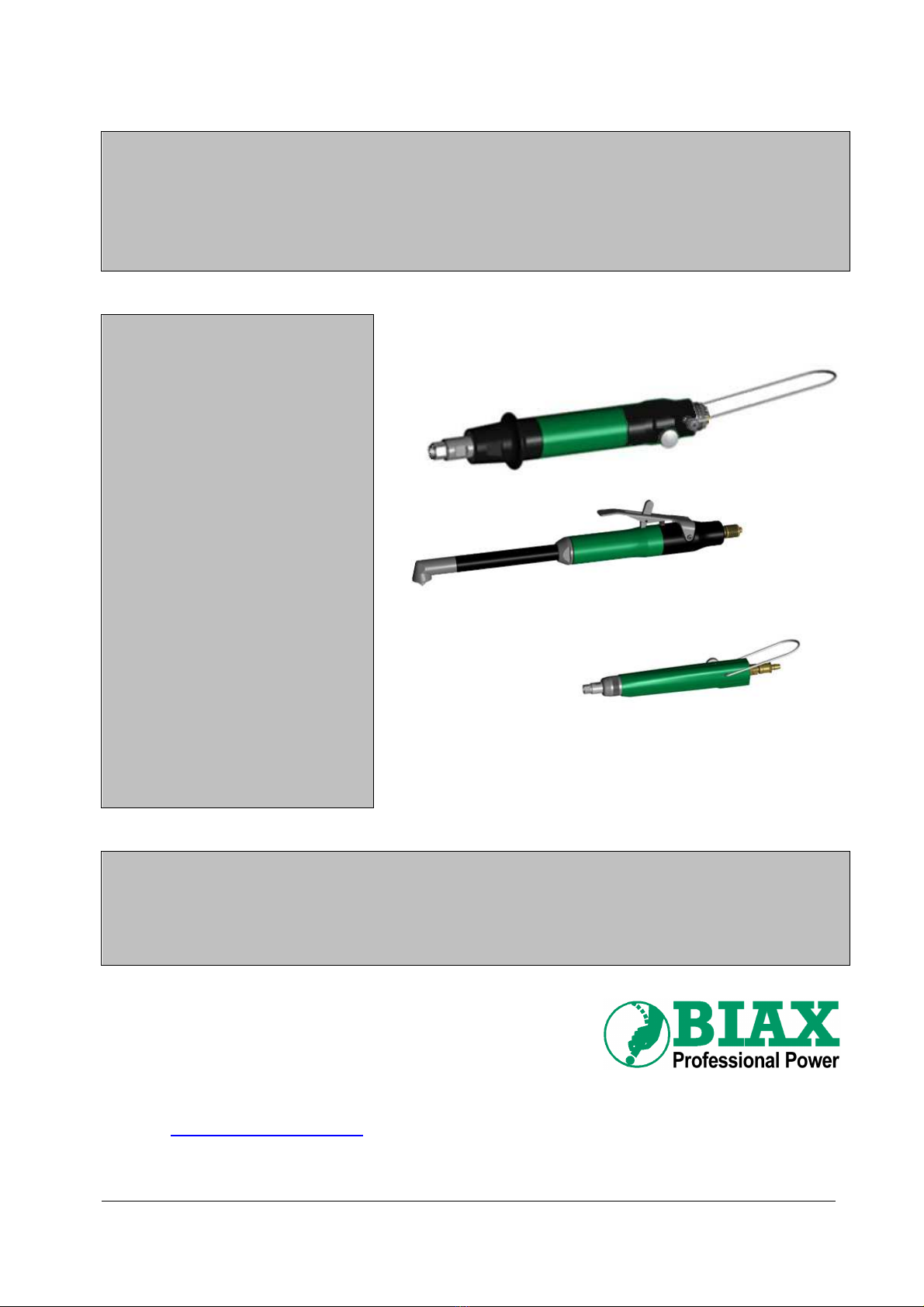
Handgeführte
Druckluft-Bohrentgrater
Hand-operated
Pneumatic Drilling Deburrer
BE 309
BEG 309
BEW 309
BEW 309 E
BEW 603
BEW 605
BEW 605 K
BEW 606
BEW 606 K
BE 805
BE 805 H
BE 1005
Diese Anleitung muss dem Anwender (Werker) ausgehändigt werden!
A copy of this manual must be given to all personnel working with this tool!
Schmid und Wezel GmbH & Co.
KG
Maschinenfabrik
Maybachstraße 2
D -75433 Maulbronn
Telefon: 07043 / 102-0
Telefax: 07043 / 102-78
E-Mail:
Webadresse: www.biax.de

Originalbetriebsanleitung für
handgeführte Druckluft-Bohrentgrater
BA-NR.: 001 580 355 2 von 15
Stand 29.07.2014
Technische Daten
Typ
Leistung
Leerlaufdrehzahl
Betriebsdruck
Empfohlene
Schlauchweite
Anschluss-
gewinde
Max. Werkzeug-
aufnahme
Einsetzbar für
Bohrungen
Geräuschpegel
Luftverbrauch
Vibration
(ISO 28662)
Gewicht
W 1/min bar mm mm mm dB(A) l/min m/s² g
BE 309 20 0-900 6 4,5 M5 Ø3 5,5 71 150 <2,5 150
BEG 309 20 0-900 6 4,5 M5 Ø3 5,5 71 150 <2,5 150
BEW 309 20 1000 6 4,5 M5 SKT 3 10 71 150 <2,5 310
BEW 309 E 20 0-1000 6 4,5 M5 SKT 3 10 71 150 <2,5 310
BEW 603 80 0-300 6 7 G 1/8" SKT 6,3 14 71 300 <2,5 980
BEW 605 80 0-500 6 7 G 1/8" Ø6 24 71 300 <2,5 820
BEW 605 K 80 0-500 6 7 G 1/8" Ø6 24 71 300 <2,5 620
BEW 606 80 0-600 6 7 G 1/8" SKT 6,3 14 71 300 <2,5 980
BEW 606 K 80 0-600 6 7 G 1/8" SKT 6,3 14 71 300 <2,5 630
BE 805 80 0-500 6 7 G 1/8" Ø8 24 71 280 <2,5 520
BE 805 H 80 500 6 7 G 1/8" Ø8 24 71 280 <2,5 570
BE 1005 200 0-500 6 7 G 1/8" Ø10 29 78 480 <2,5 1370
Originalbetriebsanleitung für
handgeführte Druckluft-Bohrentgrater
BA-NR.: 001 580 355 3 von 15
Stand 29.07.2014
Allgemeine Hinweise
Diese Betriebsanleitung ist Bestandteil des Liefer-
umfangs. Sie ist in leserlichem Zustand in Zugriffs-
nähe bereitzuhalten und bleibt auch bei Weiterverkauf
des Gerätes beim Gerät.
Diese Betriebsanleitung richtet sich an eingewiesenes
und autorisiertes Fachpersonal.
Änderungen durch technische Weiterentwicklungen
gegenüber den in dieser Betriebsanleitung darge-
stellten Ausführungen behalten wir uns vor.
Nachdrucke, Übersetzungen und Vervielfältigungen in
jeglicher Form, auch auszugsweise, bedürfen der
schriftlichen Zustimmung des Herausgebers.
Das Urheberrecht liegt beim Hersteller.
Verantwortlichkeit des Betreibers
Der Betreiber hat die geltenden nationalen Unfall-
verhütungsvorschriften und technischen Regeln
einzuhalten.
Der Betreiber darf das Gerät nur von geschultem und
zuverlässigem Personal bedienen lassen.
Der Betreiber hat dafür Sorge zu tragen, dass die
Bediener die Betriebsanleitung gelesen und verstan-
den haben, bevor sie das Gerät bedienen.
Der Betreiber hat dafür zu sorgen, dass kein Unbe-
fugter an das Gerät gelangen und dieses nutzen
kann.
Die innerbetrieblichen Arbeitsschutzvorschriften sind
zu beachten.
Bestimmungsgemäße Verwendung
Die BIAX-Druckluft-Bohrentgrater werden zum hand-
geführten
•Ansenken und
•Entgraten
von Bohrungen benutzt:
BE 309, BEG 309
für Bohrungen ∅2 - 5,5 mm
BEW 309, BEW 309 E
für Bohrungen ∅2 - 10 mm
BEW 603, BEW 606, BEW 606 K
für Bohrungen ∅3,5 - 14 mm
BE 805, BE 805 H, BEW 605, BEW 605 K
für Bohrungen ∅3,5 - 24 mm
BE 1005
für Bohrungen ∅6 - 29 mm
Verwenden Sie die BIAX-Druckluft-Bohrentgrater
keinesfalls zum Entgraten von Außenkanten oder mit
überdimensionierten Werkzeugen.
Jeglicher Missbrauch der BIAX-Druckluft-
Bohrentgrater außerhalb der oben genannten
Einsatzgebiete sowie bauliche Veränderung der
Maschinen ist ohne Zustimmung durch Schmid &
Wezel nicht zulässig. Bei Zuwiderhandlung entfällt
jegliche Haftung für Folgeschäden.
Sicherheit
Sicherheitskennzeichnung
Folgende Signalwörter werden in Verbindung mit
Sicherheitszeichen zur Darstellung möglicher
Gefahren in diesem Dokument verwendet:
Gefahr!
Tod oder schwere Körperverletzung
werden eintreten, wenn die entspre-
chenden Vorsichtsmaßnahmen
nicht getroffen werden!
Warnung!
Tod oder schwere Körperverletzung
können eintreten, wenn die entspre-
chenden Vorsichtsmaßnahmen
nicht getroffen werden!
Vorsicht!
Leichte Körperverletzung kann
eintreten, wenn die entsprechenden
Vorsichtsmaßnahmen nicht
getroffen werden!
Achtung!
Sachschaden kann eintreten, wenn
die entsprechenden Vorsichtsmaß-
nahmen nicht getroffen werden!
Sicherheitshinweise
Warnung!
Bei Nichtbeachtung der Sicher-
heitshinweise besteht akute
Verletzungsgefahr!
Beim Entgraten können Späne die
Augen verletzen. Tragen Sie bei der
Arbeit immer eine Schutzbrille!
Je nach Art der Bearbeitung kann
der angegebene Geräuschpegel
überschritten werden.
Verwenden Sie einen Gehörschutz!
Arbeiten Sie bei Staubentwicklung
nur mit Atemschutz und schalten
Sie die Staubabsaugung an Ihrem
Arbeitsplatz ein!
Verletzungsgefahr durch scharf-
kantige Werkstücke!
Tragen Sie bei der Arbeit ggf.
passende Schutzhandschuhe!

Originalbetriebsanleitung für
handgeführte Druckluft-Bohrentgrater
BA-NR.: 001 580 355 4 von 15
Stand 29.07.2014
Gesundheit
Vorsicht!
Vibration kann auf den ganzen
Körper, speziell auf Arme und
Hände, übertragen werden.
Sehr starke sowie andauernde
Vibration kann Nerven- und
Gefäßstörungen verursachen!
Vibrationen sind schädlich für Hände und Arme.
Reduzieren Sie die Zeit, in der Sie Vibrationen aus-
gesetzt sind. Beenden Sie sofort die Arbeit, wenn Sie
in den Händen Schmerzen, Kribbeln o. ä. Symptome
verspüren. Suchen Sie einen Arzt auf.
Kleidung, Schmuck, Haare u. ä. können durch
rotierende Teile des Bohrentgraters erfasst werden
und zu schweren Verletzungen führen.
Tragen Sie während der Arbeit nur enganliegende
Kleidungsstücke. Nehmen Sie Schmuck vor Arbeits-
beginn ab. Verwenden Sie bei langen Haaren
unbedingt ein Haarnetz!
Vermeiden Sie Kontakt mit Stromquellen. Der Bohr-
entgrater ist nicht gegen Kontakt mit Strom führenden
Teilen isoliert!
Umgang mit dem Bohrentgrater
Die Betriebsanleitung richtet sich
an eingewiesenes Fachpersonal!
Nichtbeachten der Betriebsan-
leitung kann zu Personenschäden
und Geräteausfällen führen!
Einzugsgefahr!
Während der Arbeit nur enganlie-
gende Kleidung tragen.
Nehmen Sie Schmuck vor Arbeits-
beginn ab.
Verwenden Sie bei langen Haaren
unbedingt ein Haarnetz!
Verletzungsgefahr!
Das eingeschaltete Werkzeug ist
vom Körper weg zu halten!
Nicht in laufendes Werkzeug
greifen! Werkzeug vorsichtig
handhaben!
Explosionsgefahr!
Der Bohrentgrater darf in explo-
sionsgefährdeten Bereichen nicht
eingesetzt werden!
Warnung!
Beachten Sie nachfolgende zu-
sätzliche Hinweise zum Umgang mit
dem Bohrentgrater und dem
Zubehör.
Ein Missachten der Hinweise kann
zu schweren und schwersten
Verletzungen führen!
Vor Arbeitsbeginn das Werkzeug sicher und möglichst
weit in die Spannzange bzw. in die Werkzeugauf-
nahme (betrifft BEW 309, BEW 309 E, BEW 603,
BEW 606) des Bohrentgraters einspannen.
Die Typen BE 309, BE 805 und BE 1005 starten erst,
wenn mit dem Senker auf die Bohrung gedrückt wird.
Die Typen BEW 309, BEW 309 E, BEG 309,
BEW 603, BEW 605, BEW 605 K, BEW 606,
BEW 606K und BE 805 H, über das Hebelventil in
Gang setzen und die laufende Maschine in Einsatz
bringen.
Der Bohrentgrater darf nur in einwandfreiem, funk-
tionstüchtigem Zustand betrieben werden.
Prüfen Sie vor Arbeitsbeginn und nach jeder Unter-
brechung den Bohrentgrater, das Werkzeug und den
Druckluftschlauch auf Beschädigungen.
Kontrollieren Sie den festen Sitz des Werkzeugs in
der Spannzange!
Vermeiden Sie beim und nach dem Betrieb direkten
Kontakt mit dem Werkzeug. Es ist heiß und
scharfkantig – Sie könnten sich verletzen.
Schließen Sie die Druckluftleitung nur mit einge-
spanntem Werkzeug und bei ausgeschaltetem Ventil
an!
Trennen Sie bei Werkzeugwechsel und Wartungs-
arbeiten den Bohrentgrater immer vom Druckluftnetz!
Schalten Sie bei Unterbrechung der Luftzufuhr den
Bohrentgrater sofort aus!
Der Betriebsdruck von 6 bar darf während des
Betriebes keinesfalls überschritten werden!
Die Spindel läuft nach dem Ausschalten noch nach.
Wechseln Sie das Werkzeug erst nach seinem
Stillstand!
Sichern Sie das Werkstück mit einer Spannvor-
richtung oder einem Schraubstock!
Halten Sie das Gerät sicher in der Hand!
Beachten Sie, dass im Schlauch gespeicherte
Druckluft einen unerwarteten Start des Bohrentgraters
verursachen kann!
Verwenden Sie den Bohrentgrater nur mit unbeschä-
digtem Schlauch. Prüfen Sie die Schläuche und
Anschlüsse vor Arbeitsbeginn auf Beschädigungen.
Beachten Sie die Gefahr eines schlagenden Druck-
luftschlauches!
Richten Sie den Luftstrom niemals auf sich oder
andere Personen.
Originalbetriebsanleitung für
handgeführte Druckluft-Bohrentgrater
BA-NR.: 001 580 355 5 von 15
Stand 29.07.2014
Verhalten am Arbeitsplatz
Halten Sie Ihren Arbeitsplatz in Ordnung!
Arbeiten Sie aufmerksam! Benutzen Sie das Gerät
nicht, wenn Sie müde sind oder unter dem Einfluss
von Alkohol, Drogen oder Medikamenten stehen!
Beim Betrieb des Bohrentgraters entstehen heiße
Späne und eventuell Funken. Entfernen Sie brenn-
bare Gegenstände und Materialien aus dem Arbeits-
bereich!
Konzentrieren Sie sich auf Ihre Arbeit und halten Sie
andere Personen von Ihrem Arbeitsbereich fern!
Bewahren Sie Ihre Werkzeuge sicher auf und pflegen
Sie diese sorgfältig!
Reparaturen dürfen nur von autorisiertem Fach-
personal durchgeführt werden.
Sorgen Sie für gute Beleuchtung und Belüftung des
Arbeitsplatzes.
Es wird empfohlen, eine Atemschutzmaske mit
Filterklasse P2 zu tragen. Außerdem sollten Sie
Handschuhe und Schutzkleidung tragen.
Verhalten bei Unfällen
Informieren Sie sich routinemäßig in regelmäßigen
Abständen, welche Möglichkeiten für die Erste Hilfe
zur Verfügung stehen!
Informieren Sie – nach der Erstversorgung von
Verletzten – bei Unfällen mit Personen-, Geräte- oder
Gebäudeschäden unverzüglich Ihren Vorgesetzten!
Verlassen Sie im Katastrophenfall (Brand) unver-
züglich den Arbeitsplatz!
Benutzen Sie nur die gekennzeichneten Flucht-
einrichtungen und Rettungswege. Benutzen Sie keine
Aufzüge!
Nennen Sie für den gezielten Einsatz von Rettungs-
fahrzeugen den Schweregrad der Personen- und
Sachschäden!
Transport
Halten Sie den Bohrentgrater beim Transport am
Handgriff oder am Gehäuse.
Tragen Sie den Bohrentgrater niemals am Druck-
luftschlauch.
Anschluss und Inbetriebnahme
Vorsicht!
Schließen Sie den Bohrentgrater
nur bei eingespanntem Werkzeug
und ausgeschaltetem Ventil an das
Druckluftnetz an!
Betreiben Sie den Bohrentgrater nur mit sauberer,
wasserfreier und geölter Luft! Dazu schließen Sie das
Gerät an einen Filterdruckminderer mit Wasserab-
scheider und Öler an. Der Filterdruckminderer sollte
möglichst nahe am Bohrentgrater installiert sein.
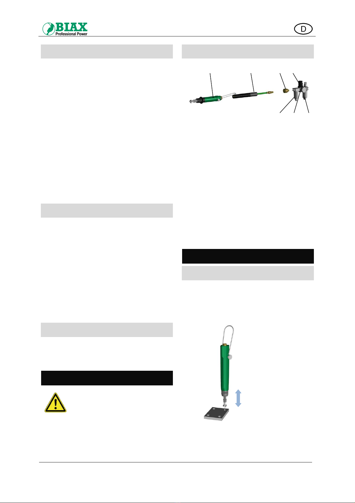
Anschluss der Zuluftleitung
Abb. 1. Anschluss an die Druckluftversorgung
Druckschlauch vor dem Anschluss durchblasen, um
Verunreinigungen zu entfernen!
Wartungseinheit (Pos. D) in folgender Reihenfolge
montieren:
Wasserabscheider/Filter mit Feinfilter von min. 40 µm
(
Pos. D1
)
–
Druckregler
(
Pos. D2
)
–
Ölnebler
(
Pos. D3
).
An der Wartungseinheit einen Betriebsdruck von max.
6 bar einstellen. Ölstand kontrollieren und ggf. Öl
nachfüllen.
Die Wartungseinheit so einstellen, dass der Luft
1 - 2 Tropfen Öl pro Minute beigemischt werden.
Alternativ kann nach 20 Arbeitsgängen 1 Tropfen Öl
aufgegeben werden.
Den Bohrentgrater (Pos. A) mit einer Schlaucheinheit
(Pos. B) über eine Einhandkupplung (Pos. C) an die
Wartungseinheit (Pos. D) anschließen.
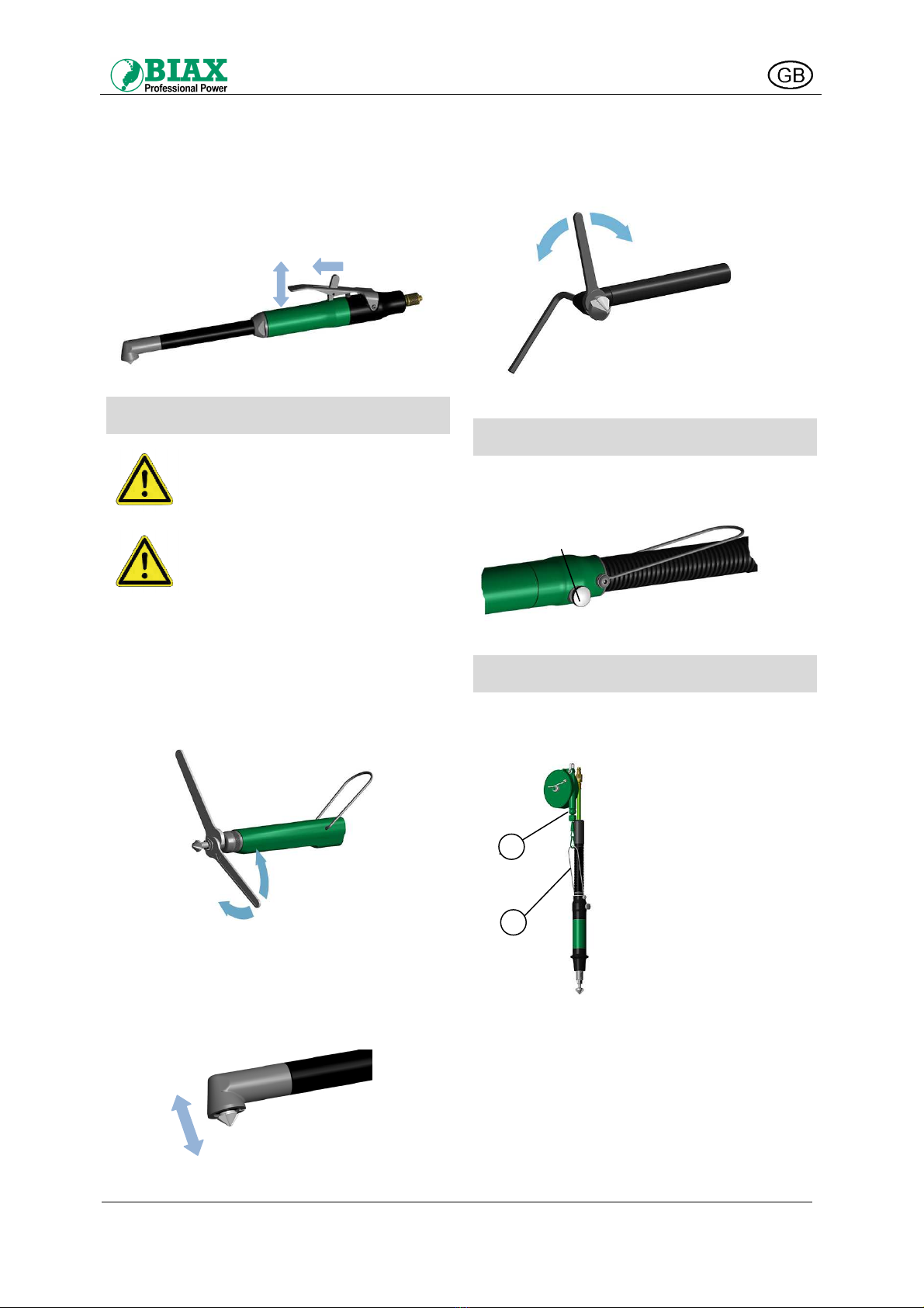
Handhabung
Ein- und Ausschalten
Typ BE 309, BE 805, BE 1005
Der Bohrentgrater startet durch Andrücken des
Werkzeugs auf das zu bearbeitende Werkstück. Zum
Abschalten heben Sie das Gerät vom Werkstück ab
(siehe Abb. 2).
.
Abb. 2. Ein- und Ausschalten mit Schubstart
A B C D
D3 D1
D2
AUS
EIN
Originalbetriebsanleitung für
handgeführte Druckluft-Bohrentgrater
BA-NR.: 001 580 355 6 von 15
Stand 29.07.2014
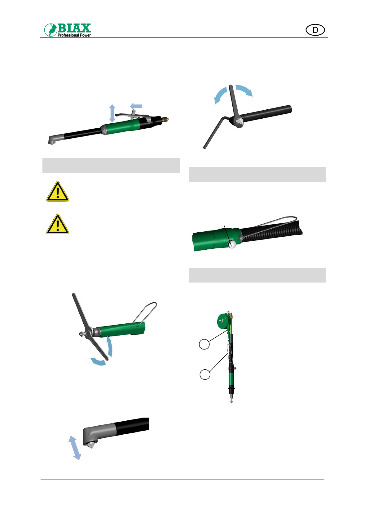
Typ BEW 309, BEG 309, BEW 603,
BEW 605, BEW 605 K, BEW 606,
BEW 606 K, BE 805 H, BEW 309 E
Das Hebelventil entsichern und Hebel zum Ein-
schalten drücken. Zum Ausschalten Hebel loslassen
(siehe Abb. 3).
Abb. 3. Ein- und Ausschalten mit Hebelventil
Werkzeugwechsel
Vorsicht!
Trennen Sie vor jedem Werkzeug-
wechsel den Bohrentgrater vom
Druckluftanschluss!
Warnung!
Keine Werkzeugschlüssel stecken
lassen! Überprüfen Sie vor Arbeits-
beginn, dass alle Schlüssel entfernt
sind!
Typ BE 309, BEG 309, BE 805, BE 805 H,
BE 1005
Mittels der im Lieferumfang enthaltenen Schlüssel die
Spindel festhalten und Spannzange (Rechtsgewinde)
öffnen oder schließen (siehe Abb. 4).
Abb. 4. Werkzeugwechsel BE/BEG
Typ BEW 309, BEW 309 E, BEW 603,
BEW 606, BEW 606 K
Den Kopfsenker einfach aus der Werkzeugaufnahme
ziehen und wieder einstecken (siehe Abb. 5).
Abb. 5. Werkzeugwechsel BEW
Typ BEW 605, BEW 605 K
Mittels der im Lieferumfang enthaltenen Schlüssel die
Spindel festhalten und Spannzange (Rechtsgewinde)
öffnen oder schließen (siehe Abb. 6).
Abb. 6. Werkzeugwechsel BEW 605
Drehzahlregelung
Die Drehzahl kann über das seitlich am Gehäuse
angebrachte Einstellrad (R) stufenlos im entspre-
chenden Drehzahlbereich (siehe Technische Daten)
eingestellt werden (siehe Abb. 7).
Abb. 7. Drehzahlregelung
Einsatz eines Federzugs (Typ BE)
Wir empfehlen zur sicheren Handhabung des Bohr-
entgraters den Aufhängebügel (A) an einem Federzug
(B) zu befestigen (siehe Abb. 8).
Abb. 8. Federzug
Bringen Sie den Federzug mit einer Schiebelaufkatze
an einem höher gelegenen Element über dem
Arbeitsplatz oder an der Decke an.
Nach Feinabstimmung sollte sich der Bohrentgrater
frei schwebend im Gleichgewicht (mit der Zugfeder)
auf Arbeitshöhe befinden.
Beachten Sie zur Feinabstimmung des Federzuges
die Hinweise des Herstellers.
ENTFERNEN
ZU
FESTHALTEN
Auf
AUS
EIN
ENTSICHERN
AUF
Zu
EINSETZEN
R
FESTHALTEN
A
B
Originalbetriebsanleitung für
handgeführte Druckluft-Bohrentgrater
BA-NR.: 001 580 355 7 von 15
Stand 29.07.2014
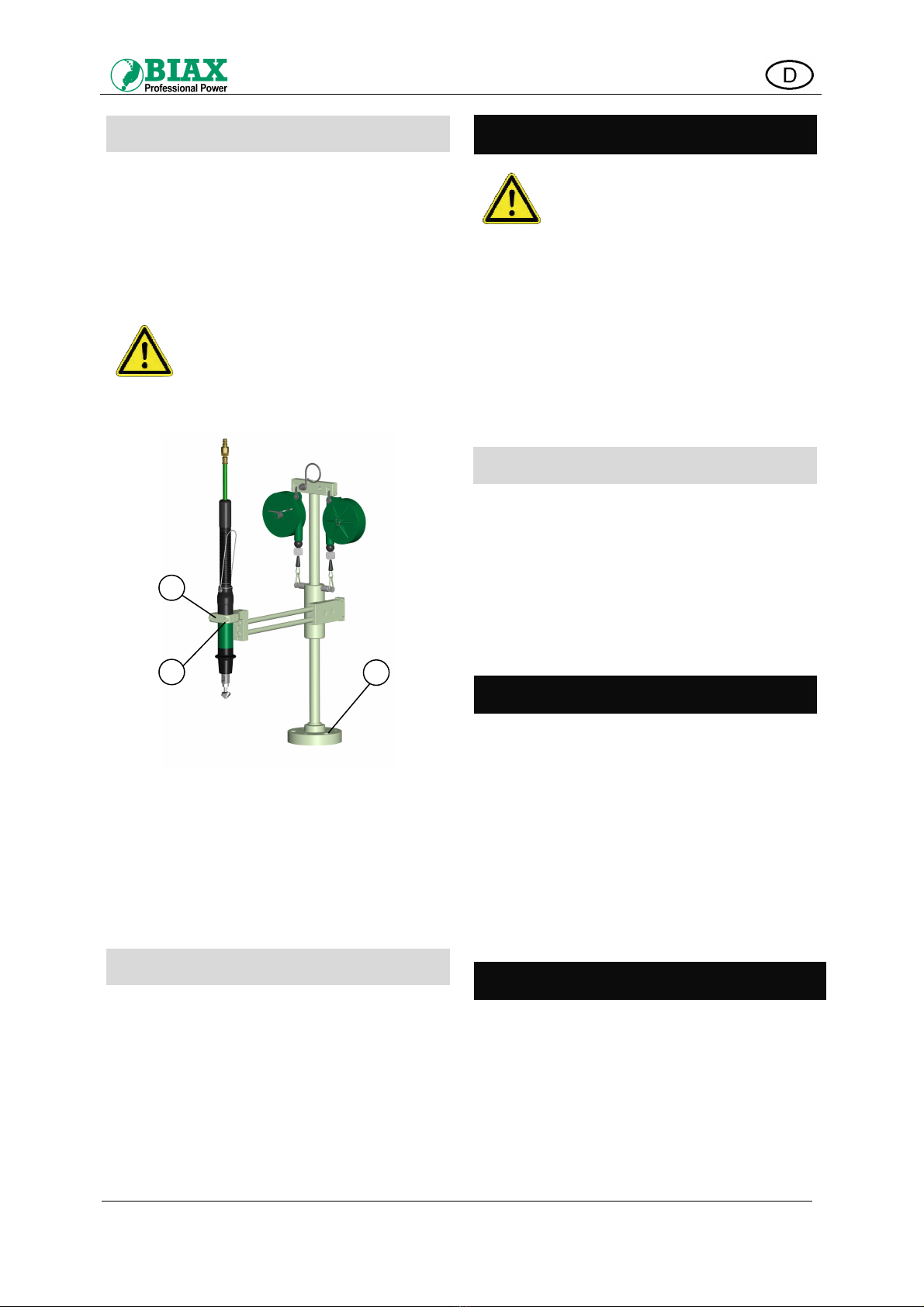
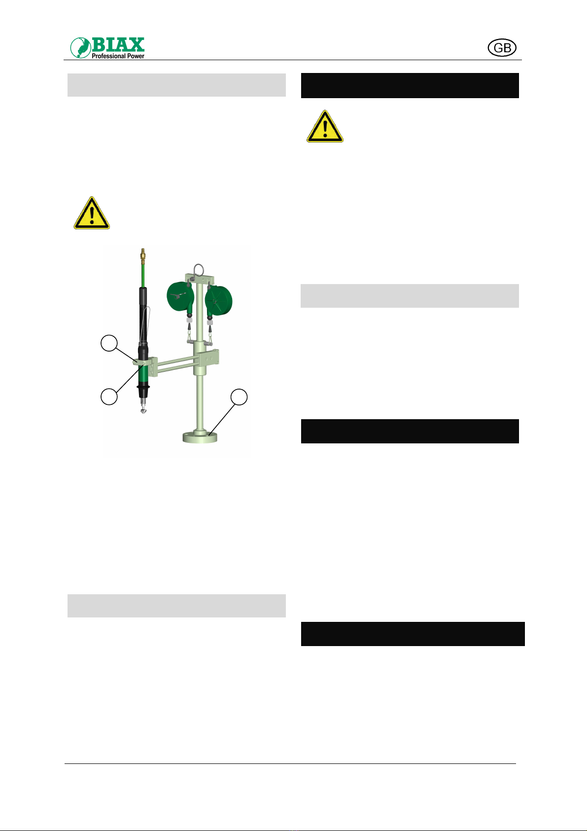
Einsatz eines Stativs (Typ BE 1005)
Ein Stativ garantiert die senkrechte Position des
Bohrentgraters über dem Werkstück und erleichtert so
die Bearbeitung des Werkstücks.
Ein geeignetes Stativ ist optional erhältlich und kann
aus unserem Katalog ausgewählt werden.
Zum Aufbau und zur Inbetriebnahme des Stativs
beachten Sie die entsprechende Betriebsanleitung
des Herstellers.
Vorsicht!
Achten Sie auf Standfestigkeit des
Stativs.
Verschrauben Sie die Grundplatte
des Stativs (C) auf ebenem, festem
Untergrund!
Abb. 9. Bohrentgrater am Stativ befestigen
•Schrauben (B) lösen und Halteklemme des
Stativs öffnen.
•Bohrentgrater am zylindrischen Bereich des
Ventils spannen! (nicht auf Griffüberzug spannen,
sonst wird der Bohrentgrater beschädigt!)
•Halteklemme (A) des Stativs wieder festschrau-
ben. Schrauben nur so stark anziehen wie nötig!
Filterdruckminderer
Die Luft aus Druckluftanlagen ist meist verunreinigt
und mit Feuchtigkeit angereichert. Zwischen Druck-
luftanlage und Werkzeug sollte deshalb ein Filter-
druckminderer mit Wasserabscheider geschaltet sein.
Dieser regelt nicht nur den Betriebsdruck, sondern
reinigt und entwässert zudem die Druckluft. Der
Nutzen und die Lebensdauer des Bohrentgraters wird
somit wesentlich erhöht.
Einen geeigneten Filterdruckminderer können Sie aus
unserem Katalog auswählen.
Wartung
Vorsicht!
Trennen Sie vor dem Durchführen
von Wartungsarbeiten den Bohrent-
grater vom Druckluftanschluss!
Das Gerät nach Gebrauch reinigen und das Werkzeug
auf Verschleiß kontrollieren. Verschlissene Werk-
zeuge rechtzeitig austauschen.
Für eine einwandfreie Funktion des Bohrentgraters
sollte die Wartungseinheit in regelmäßigen Abständen
überprüft werden. Entfernen Sie dabei vorhandenes
Kondensat und füllen Sie ggf. BIAX-Spezialöl nach.
Verschmutzte Dämpfungen und Sinterscheiben im
hinteren Teil des Gehäuses reinigen bzw. aus-
wechseln. Schrauben Sie dazu die Schlaucheinheit
und den Gewindenippel ab (Rechtsgewinde).
Überprüfung des Filterdruckminderers
Eine regelmäßige Durchführung der Wartungsarbeiten
verlängert die Lebensdauer des Bohrentgraters
erheblich. Beschädigungen an Kugellagern, Motor-
teilen und Rotor durch Schmutz oder Rostpartikel
werden dadurch vermieden.
Hierzu in regelmäßigen Abständen
•Kondenswasser entfernen und
•Fließdruck prüfen
6 bar dürfen nicht überschritten werden.
Reparatur
Achtung!
Reparaturen dürfen nur von Fach-
kräften vorgenommen werden!
Hierfür steht Ihnen unsere
Serviceabteilung zur Verfügung.
Nur Originalteile verwenden!
Bei nachlassender Leistung müssen die Rotor-
schieber ausgewechselt werden.
Wenden Sie sich bitte an die nächstgelegene
Vertragswerkstatt oder direkt an unser Stammhaus.
Entsprechende Ersatzteillisten können auf Wunsch an
die Fachwerkstätten ausgehändigt werden.
Entsorgung
Die Verpackung des Bohrentgraters besteht weit-
gehend aus recyclingfähigem Material. Entsorgen Sie
dieses umweltgerecht.
Werfen Sie den Bohrentgrater am Ende der Lebens-
zeit nicht in den normalen Müll. Erkundigen Sie sich
nach Möglichkeiten einer umwelt- und sachgerechten
Entsorgung.
Beachten Sie dabei die örtlichen und nationalen
Regelungen zur Entsorgung.
C
B
A

Originalbetriebsanleitung für
handgeführte Druckluft-Bohrentgrater
BA-NR.: 001 580 355 8 von 15
Stand 29.07.2014
Zubehör
Im Lieferumfang enthalten sind der BIAX-Druckluft-
Bohrentgrater mit Schlaucheinheit und Zubehör.
Sonderzubehör
Sonderzubehör finden Sie in unserem Katalog:
Druckluftarmaturen, Einhandkupplung mit Außenge-
winde oder Schlauchanschluss, Filterdruckminderer,
Schalldämpfer, Schlauchbalancer, Schlaucheinheiten,
Spannzangen, Spiralschläuche und Werkbankaus-
rüstungen.
Spezialöl finden Sie in unserem Katalog.

Translation of original operating manual for
hand-operated pneumatic drilling deburrer
BA-NR.: 001 580 355 9 of 15
Stand 29.07.2014
Technical data
Model
Power
Idle speed
Operating
pressure
Recommended
hose diameter
Connecting
thread
Max. tool
receptacle
diameter
Suitable for bore
holes
Noise level
Air consumption
Vibration
(ISO 28662)
Weight
W 1 rpm bar mm mm mm dB(A) l/min m/s² g
BE 309 20 0-900 6 4.5 M5 Ø3 5.5 71 150 <2.5 150
BEG 309 20 0-900 6 4.5 M5 Ø3 5.5 71 150 <2.5 150
BEW 309 20 1000 6 4.5 M5 HEX 3 10 71 150 <2.5 310
BEW 309 E 20 0-1000 6 4.5 M5 HEX 3 10 71 150 <2.5 310
BEW 603 80 0-300 6 7 G 1/8" HEX 6.3 14 71 300 <2.5 980
BEW 605 80 0-500 6 7 G 1/8" Ø6 24 71 300 <2.5 820
BEW 605 K 80 0-500 6 7 G 1/8" Ø6 24 71 300 <2.5 620
BEW 606 80 0-600 6 7 G 1/8" HEX 6.3 14 71 300 <2.5 980
BEW 606 K 80 0-600 6 7 G 1/8" HEX 6.3 14 71 300 <2.5 630
BE 805 80 0-500 6 7 G 1/8" Ø8 24 71 280 <2.5 520
BE 805 H 80 500 6 7 G 1/8" Ø8 24 71 280 <2.5 570
BE 1005 200 0-500 6 7 G 1/8" Ø10 29 78 480 <2.5 1370

Translation of original operating manual for
hand-operated pneumatic drilling deburrer
BA-NR.: 001 580 355 10 of 15
Stand 29.07.2014
General instructions
The operating manual is an integral part of the
delivery. A copy of this manual must be kept near the
machine. In the event of sale of the machine, the
manual must be handed over to the new owner.
This operating manual has been compiled for use by
suitably trained and authorised technical personnel.
Our products might be modified from time to time, due
to technical development.
No part of this document may be reproduced,
transmitted, transcribed or stored in any retrievable
form by any means (xeroxing, microfilm or other)
without the prior written consent of the publisher.
The manufacturer retains the copyright to this manual.
Liability of the machine owner
The owner of the machine must at all times comply
with the applicable statutory safety regulations and the
applicable technical instructions and standards.
All work on the machine must be carried out by
specially trained, reliable technical personnel.
The machine owner must ensure that all operating
personnel have read and fully understood this
operating manual prior to operating the machine.
Secure the machine in such a manner that no
unauthorised person can operate it.
Always comply with the relevant internal health and
safety rules.
Proper use
The BIAX pneumatic drilling deburrer is used for the
hand-guided
•countersinking and
•deburring
of drilled holes:
BE 309, BEG 309
for holes ∅2 - 5.5 mm
BEW 309, BEW 309 E
for holes ∅2 - 10 mm
BEW 603, BEW 606, BEW 606 K
for holes ∅3.5 - 14 mm
BE 805, BE 805 H, BEW 605, BEW 605 K
for holes ∅3.5 - 24 mm
BE 1005
for holes ∅6 - 29 mm
Never use the BIAX pneumatic drilling deburrer to
deburr edges. Do not use the deburring bit together
with overdimensioned tools.
Any other use of the BIAX pneumatic drilling
deburrer is deemed improper and prohibited.
Modifications to the drilling deburrer are only
permitted with the explicit consent of Schmid &
Wezel. Schmid & Wezel shall not be held liable for
damage resulting from non-compliance with the
instructions in this manual.
Safety
Safety signs
The safety signs below show the signal words relating
to possible risks and consequences:
Danger!
Non-compliance with the respective
instructions can result in serious or
even fatal injury and damage to
property!
Warning!
Non-compliance with the respective
instructions can result in serious or
even fatal injury and damage to
property!
Caution!
Non-compliance with the respective
instructions can result in injury!
Caution!
Non-compliance with the respective
instructions can result in damage
to property!
Safety instructions
Warning!
In the event of non-compliance with
the safety instructions, there is a
high risk of injury to operating staff
and other persons!
Risk of injury to eyes from small
metal chips produced by deburring.
Always wear protective goggles
when working with the machine!
Depending on the worked material,
the normal noise level (see technical
data) may be exceeded.
Always wear hearing protection!
If there is dust during machining,
always wear a protective mask and
switch on the dust extraction
system at your workplace.
Risk of injury from sharp-edged
workpieces!
If necessary, wear safety gloves!
Translation of original operating manual for
hand-operated pneumatic drilling deburrer
BA-NR.: 001 580 355 11 of 15
Stand 29.07.2014
Health protection
Caution!
Exposure of hands, arms and body
to vibration.
Strong and continuous vibration
may lead to neural and vascular
dysfunctions!
Vibration can cause damage to hands and/or upper
limbs. Therefore, keep the time during which you are
exposed to vibration to a minimum! If you experience
pain, tingling or similar symptoms in your hands,
switch off the machine without delay. Seek medical
advice.
Loose clothing, jewellery or hair might become
entangled in the rotating parts of the drilling deburrer,
resulting in serious injury.
When working with the machine, wear tight-fitting
clothing. Do not wear any jewellery. Long hair must be
covered with a hairnet!
Do not touch electrical components and connections.
The drilling deburrer is not completely insulated
against powered components!
Handling of pneumatic drilling
deburrer
This operating manual has been
compiled for use by suitably
trained technical personnel.
Non-compliance with the
instructions in this manual can
lead to injury and damage to the
machine!
Risk of entanglement!
Wear tight-fitting clothing.
Do not wear any jewellery.
Long hair must be covered with a
hairnet!
Risk of injury!
Keep the powered machine away
from your body!
Never reach into the machine while
it is powered! Handle the machine
with the appropriate care!
Risk of explosion!
The drilling deburrer must not be
used in potentially explosive
atmospheres!
Warning!
When handling the drilling deburrer
and its accessories, strictly adhere
to the instructions below.
Non-compliance can result in
serious or even fatal injury!
Before starting work with the deburrer, insert the bit as
deep as possible into the chuck or the tool receptacle
(in models BEW 309/ BEW 603 / BEW 606) of the
drilling deburrer and secure it.
Models BE 309, BE 805 and BE 1005 can only be
started, if the bit is pressed against the borehole.
When working with models BEW 309, BEW 309 E,
BEG 309, BEW 603, BEW 605, BEW 605 K, BEW
606, BEW 606K and BE 805 H, start the deburrer with
the lever valve and then begin to deburr the
boreholes.
The drilling deburrer must only be operated when it is
in proper working order and fully functional.
At the start of each shift, and after prolonged breaks,
inspect the deburrer, the tool bit and the pneumatic
hose for visible damage.
Ensure that the tool bit is properly secured in the drill
chuck.
During and after operation, avoid any contact with the
tool bit, as it is hot and sharp-edged.
Prior to connecting the compressed air line, mount the
tool and ensure that the valve is switched off!
Before changing the tool or carrying out maintenance
work on the deburrer, always disconnect the machine
from the compressed air supply line!
If there is an interruption in the supply of compressed
air, immediately switch off the machine!
During operation, the operating pressure must not
exceed 6 bar!
When the machine is switched off, the spindle
continues rotating for a short while. Replace the tool
only after it has come to a standstill!
To secure the tool, use a vice or other clamping
device!
When working with the machine, hold it firmly!
Please note that compressed air in the hose might
lead to unexpected start-up of the drilling deburrer!
The hose attached to the drilling deburrer must be in
proper working order. Prior to working with the
deburrer, inspect the hose and all couplings for
damage!
Be aware of the risk caused by flapping air hoses!
Never aim the air flow directly at yourself or other
persons.
Workplace safety
Keep your workplace tidy!
Work with the necessary care and diligence! Do not
operate the machine, if you feel tired or are under the
influence of alcohol, medication or drugs!
During machine operation, hot metal chips and sparks
might be propelled away from the borehole. Remove
all flammable objects and materials from the work
area!

Translation of original operating manual for
hand-operated pneumatic drilling deburrer
BA-NR.: 001 580 355 12 of 15
Stand 29.07.2014
When working with the deburrer, concentrate your
mind on the task in hand and keep other persons
away from your workplace!
Store your tools safely and service them regularly and
with the necessary care!
All repairs must be performed by authorised specialist
technicians.
Ensure that the work area is adequately illuminated
and ventilated.
We recommend wearing a dust mask of filter class P2.
Always wear safety gloves and protective clothing.
Appropriate behaviour in case of an
accident
Inform yourself of the location of the first-aid kits on
site and make yourself familiar with the emergency
procedures!
In the event of an accident that has caused damage to
persons, machinery or the building, attend to the
casualties and then inform your supervisor!
In the event of a catastrophe (e.g. fire), leave your
workplace as quickly as possible.
Follow the escape routes and emergency signs. Do
not use lifts!
When alerting the emergency services state the
nature of the accident, the number of casualties and
the nature of their injuries!
Transport
To transport the drilling deburrer, hold it by its handle
or housing.
Never lift the drilling deburrer by the compressed air
hose.
Connection and start-up
Caution!
Prior to connecting the drilling
deburrer to the compressed air
supply line, ensure that the tool is
properly mounted and the valve is
closed!
The BIAX drilling deburrer must only be operated with
clean, dry and lubricated air! To ensure this, connect
the machine to a filter pressure reducer with a water
trap and oiler! The filter pressure reducer should be
installed as close as possible to the drilling deburrer.
Connection to compressed air supply
line
Abb. 10. Connection to compressed air supply
Prior to connecting the pressure hose, blow through it
to remove any dirt!
Assemble the maintenance unit (item D) in by
performing the following steps in the prescribed
sequence:
Water trap/filter with fine filter of at least 40 µm
(
item D1
)
–
pressure regulator
(
item D2
)
–
aerosol
lubricator
(
item D3
).
At the maintenance unit, set the operating pressure to
max. 6 bar. Check the oil level and add oil, if
necessary.
Set the maintenance unit to an air lubrication rate of 1
to 2 drops of oil per minute. Alternatively, add 1 drop
of oil every 20 cycles.
Connect the standard pneumatic drilling deburrer
(item A) to the maintenance unit (item D), using the
hose (item B) and the one-hand coupling (item C).
Operation
Switching on/off
Models BE 309, BE 805, BE 1005
To start the drilling deburrer, press the tool onto the
workpiece to be machined. To switch off the drilling
deburrer, lift the tool from the workpiece (see Abb.
11).
.
Abb. 11. Switching on/off with push start
A B C D
D3 D1
D2
OFF
ON
Translation of original operating manual for
hand-operated pneumatic drilling deburrer
BA-NR.: 001 580 355 13 of 15
Stand 29.07.2014
Models BEW 309, BEG 309, BEW 603,
BEW 605, BEW 605 K, BEW 606,
BEW 606 K, BE 805 H, BEW 309 E
Release the lever valve and press the lever down. To
switch off the drilling deburrer, release the lever (see Abb.
12).
Abb. 12. Switching on/off with lever valve
Tool change
Caution!
Before changing the tool, disconnect
the drilling deburrer from the
compressed air supply line!
Warning!
Never leave spanners or wrenches
attached to the tool! Before starting
the machine, check that all
spanners and wrenches have been
removed!
Models BE 309, BEG 309, BE 805,
BE 805 H, BE 1005
Using the spanner supplied with the machine, hold the
spindle and open/close the chuck (right-hand thread)
(see Abb. 13).
Abb. 13. Tool change in models BE/BEG
Models BEW 309, BEW 309 E, BEW 603,
BEW 606, BEW 606 K
Pull the countersinking head from the tool receptacle
and insert a new one (see Abb. 14).
Abb. 14. Tool change in model BEW
Models BEW 605, BEW 605 K
Using the spanner supplied with the machine, hold the
spindle and open/close the chuck (right-hand thread)
(see Abb. 15).
Abb. 15. Tool change in model BEW 605
Speed control
The speed can be continuously adjusted within the set
speed range (see technical data) by turning the rotary
switch (R) located on the handle (see Abb. 16).
Abb. 16. Speed control
Use of balancer (model BE)
For the safe handling and operation of the drilling
deburrer, we recommend attaching the suspension
bracket (A) to a balancer (B) (see Abb. 8).
Abb. 17. Balancer
The pulley must be attached to a sliding crab secured
to a beam or the ceiling above the workplace.
Adjust the pulley mechanism so that the drilling
deburrer is suspended at working height.
To adjust the pulley mechanism, following the
instructions of the pulley manufacturer.
REMOVE
CLOSE
HOLD
OPEN
OFF
ON
RELEASE
OPEN
CLOSE
INSERT
R
HOLD
A
B
Translation of original operating manual for
hand-operated pneumatic drilling deburrer
BA-NR.: 001 580 355 14 of 15
Stand 29.07.2014
Use of stand (model BE 1005)
The use of a stand is recommended, as it ensures
proper vertical positioning of the drilling deburrer over
the workpiece. This makes its operation more
accurate and also safer.
For suitable stands, see our catalogue.
Install and operate the stand according to the
instructions of the respective manufacturer.
Caution!
Check the stability of the stand.
Screw the base plate of the stand
(C) to a level and firm surface!
Abb. 18. Securing the drilling deburrer to the stand
•Loosen the screws (B) and open the clamping
mechanism of the stand.
•Place the drilling deburrer in the clamping
mechanism and secure it along the cylinder-
shaped section of the valve. Do not clamp it
across the handle padding, as this causes
damage to the machine!
•Tighten the clamping mechanism (A) of the stand.
Tighten the screws only as tight as necessary!
Filter pressure reducer
The air supplied by a compressed air system is
generally contaminated and contains a considerable
amount of moisture. It is therefore advisable to install
a filter pressure reducer with a water trap between the
compressed air system and the machine. This reducer
controls the operating pressure and also filters and
dries the compressed air, significantly prolonging the
service life of the drilling deburrer.
For suitable filter pressure reducers, please refer to
our catalogue.
Maintenance
Caution!
Before performing any maintenance
work, disconnect the drilling
deburrer from the compressed air
supply line!
After use, clean the machine and check the tool for
wear. Always replace worn tools.
To ensure proper functioning of the drilling deburrer,
regularly inspect the maintenance unit. Drain off any
condensate and top up with BIAX special oil, if
necessary.
Inspect the damping and sintered plates in the rear
section of the housing and clean or replace them, if
necessary. To do this, disconnect the hose kit and the
threaded nipple (right-hand thread).
Inspection of filter pressure reducer
Regular servicing of the machine prolongs the service
life of the drilling deburrer. It helps prevent damage
from dirt particles, rust, etc. to ball bearings, motor
parts and the rotor.
Please proceed as follows:
•Regularly drain off the condensate.
•Regularly check the operating pressure
(maximum admissible pressure: 6 bar).
Repair
Caution!
All repairs must be performed by
specialist technicians. Schmid &
Wezel operates an extensive after-
sales service network that can
assist you in this task.
Use only original parts!
In the event of reduced machine performance, replace
the rotary slides.
For more information on our after-sales services,
contact your local authorised repair shop or the
Schmid & Wezel customer service department.
Spare parts lists are available on request from any
authorised repair shop.
Disposal
The packaging of the drilling deburrer is almost
entirely made of recyclable materials. Please dispose
of the packaging material according to the
environmental regulations.
At the end of its service life, do not dispose of the
drilling deburrer with normal household waste. Ask
your local authorities about the facilities for an
appropriate disposal and recycling.
Observe all statutory waste disposal regulations.
C
B
A

Translation of original operating manual for
hand-operated pneumatic drilling deburrer
BA-NR.: 001 580 355 15 of 15
Stand 29.07.2014
Accessories
The BIAX pneumatic drilling deburrer is delivered with
a hose kit and standard accessories.
Optional extras
For suitable pneumatic fittings, one-hand couplings
(male couplings or hose couplings), hose kits,
silencers, hose balancers, hose units, chucks, spiral
hoses, workbench equipment, etc., please refer to our
catalogue.
For special oil products, see our catalogue.
This manual suits for next models
11
Table of contents
Languages:
Other BIAX Power Tools manuals


