Big Backyard HILLCREST F23270 User manual
INSTALLATION AND OPERATING INSTRUCTIONS
10-14 Hrs
To reduce the risk of serious injury or death, you must read and
follow these instructions. Keep and refer to these instructions often
and give them to any future owner of this play system. Manufacturer contact information provided below.
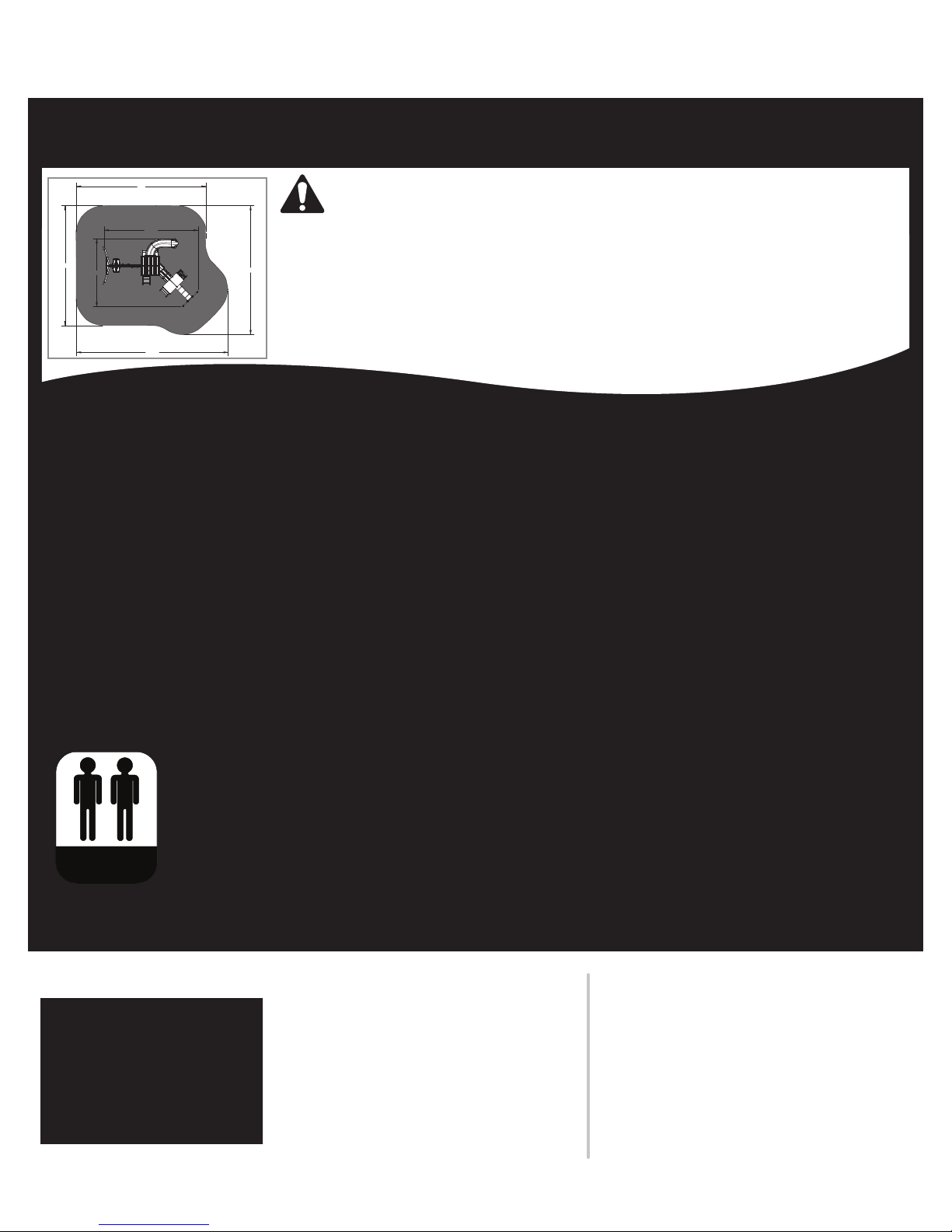
OBSTACLE FREE SAFETY ZONE - 32’9” x 28’ area requires Protective Surfacing. See page 3.
MAXIMUM VERTICAL FALL HEIGHT - 6’5”
CAPACITY - 11 Users Maximum, Ages 3 to 10; Weight Limit 110 lbs. (49.9 kg) per child.
RESIDENTIAL HOME USE ONLY. Not intended for public areas such as schools, churches, nurseries, day cares or parks.
Two person
assembly
WARNING
28'
32'-9"
15'-2"
26' 28'
HILLCREST
21'-4"
3403270 Rev 02/14/2013
Table of Contents
Warnings and Safe Play Instructions. . . . . . . . . . . . . . . pg. 2
Protective Surfacing Guidelines. . . . . . . . . . . . . . . . . . . pg. 3
Instructions for Proper Maintenance . . . . . . . . . . . . . . . pg. 4
About Our Wood – Limited Warranty . . . . . . . . . . . . . . pg. 5
Keys to Assembly Success . . . . . . . . . . . . . . . . . . . . . . pg. 6
Metric Conversion Sheets . . . . . . . . . . . . . . . . . . . . . pg. 7,8
Part ID .......................................pg. 9
Installation of I.D./Warning Plaque . . . . . . . . . . . .Final Step
HILLCREST PLAY SYSTEM – F23270
Solowave Design
375 Sligo Rd. West, PO Box 10
Mount Forest, ON Canada N0G 2L0
General Inquiries:
8:00am - 4:30pm EST
Toll Free: 1-877-966-3738
Warnings and Safe Play Instructions
CONTINUOUS ADULT SUPERVISION REQUIRED. Most serious injuries and deaths on playground equipment have occurred
while children were unsupervised! Our products are designed to meet mandatory and voluntary safety standards. Complying
with all warnings and recommendations in these instructions will reduce the risk of serious or fatal injury to children using
this play system. Go over the warnings and safe play instructions regularly with your children and make certain that they
understand and follow them. Remember on-site adult supervision is required for children of all ages.
Observe capacity limitations of your play-set. See
front cover.
Dress children with well fitting and full foot enclosing
footwear.
Teach children to sit with their full weight in the center
of the swing seat to prevent erratic swing motion or
falling off.
Check for splintered, broken or cracked wood; missing,
loose, or sharp edged hardware. Replace, tighten and or
sand smooth as required prior to playing.
Verify that suspended climbing ropes, rope ladders, chain
or cable are secured at both ends and cannot be looped
back on itself as to create an entanglement hazard.
On sunny and or hot days, check the slide and other
plastic rides to assure that they are not very hot as to
cause burns. Cool hot slide and rides with water and wipe
dry prior to using.
Do not allow children to wear open toe or heel footwear
like sandals, flip–flops or clogs.
Do not allow children to walk, in front, between, behind
or close to moving rides.
Do not let children twist swing chains or ropes or loop
them over the top support bar. This may reduce the
strength of the chain or rope and cause premature failure.
Do not let children get off rides while they are in motion.
Do not permit climbing on equipment when it is wet.
Do not permit rough play or use of equipment in a
manner for which it was not intended. Standing on or
jumping from the roof, elevated platforms, swings,
climbers, ladders or slide can be dangerous.
Do not allow children to swing empty rides or seats.
Do not allow children to go down slide head first or
run up slide.
2
SERIOUS HEAD INJURY HAZARD
Installation over concrete, asphalt, dirt, grass, carpet
and other hard surface creates a risk of serious injury
or death from falls to the ground. Install and maintain
shock absorbing material under and around play-set as
recommended on page 3 of these instructions.
COLLISION HAZARD
Place play-set on level ground at least 6 feet from any
obstruction such as a garage or house, fences, poles,
trees, sidewalks, walls, landscape timbers, rocks,
pavement, planters, garden borders, overhanging
branches, laundry lines, and electrical wires. (See
OBSTACLE FREE SAFETY ZONE on cover)
CHOKING HAZARD
Prior to assembly, this product contains small parts.
DO NOT allow children less than 5 years of age near or
around loose nuts, screws, washers, plastic bags and
other small parts.
WARNING LABEL
Owners shall be responsible for maintaining the legibility
of the warning labels.
STRANGULATION HAZARD
• NEVER allow children to play with ropes, clotheslines,
pet leashes, cables, chains or cord-like items when using
this play-set or to attach these items to play-set.
• NEVER allow children to wear loose tting clothing,
ponchos, hoods, scarves, capes, necklaces, items with
draw-strings, cords or ties when using this play-set.
• NEVER allow children to wear bike or sport helmets
when using this play-set.
Failure to prohibit these items, even helmets with chin
straps, increases the risk of serious injury and death to
children from entanglement and strangulation.
TIP OVER HAZARD
Choose a level location for the equipment. This can reduce
the likelihood of the play set tipping over and loose-fill
surfacing materials washing away during heavy rains.
DO NOT allow children to play on the play-set until the
assembly is complete and the unit is properly anchored.
WARNING
WARNING – Safe Play Instructions
Warnings and Safe Play Instructions
CONTINUOUS ADULT SUPERVISION REQUIRED. Most serious injuries and deaths on playground equipment have occurred
while children were unsupervised! Our products are designed to meet mandatory and voluntary safety standards. Complying
with all warnings and recommendations in these instructions will reduce the risk of serious or fatal injury to children using
this play system. Go over the warnings and safe play instructions regularly with your children and make certain that they
understand and follow them. Remember on-site adult supervision is required for children of all ages.
Observe capacity limitations of your play-set. See
front cover.
Dress children with well fitting and full foot enclosing
footwear.
Teach children to sit with their full weight in the center
of the swing seat to prevent erratic swing motion or
falling off.
Check for splintered, broken or cracked wood; missing,
loose, or sharp edged hardware. Replace, tighten and or
sand smooth as required prior to playing.
Verify that suspended climbing ropes, rope ladders, chain
or cable are secured at both ends and cannot be looped
back on itself as to create an entanglement hazard.
On sunny and or hot days, check the slide and other
plastic rides to assure that they are not very hot as to
cause burns. Cool hot slide and rides with water and wipe
dry prior to using.
Do not allow children to wear open toe or heel footwear
like sandals, flip–flops or clogs.
Do not allow children to walk, in front, between, behind
or close to moving rides.
Do not let children twist swing chains or ropes or loop
them over the top support bar. This may reduce the
strength of the chain or rope and cause premature failure.
Do not let children get off rides while they are in motion.
Do not permit climbing on equipment when it is wet.
Do not permit rough play or use of equipment in a
manner for which it was not intended. Standing on or
jumping from the roof, elevated platforms, swings,
climbers, ladders or slide can be dangerous.
Do not allow children to swing empty rides or seats.
Do not allow children to go down slide head first or
run up slide.
WARNING
WARNING – Safe Play Instructions
2
SERIOUS HEAD INJURY HAZARD
Installation over concrete, asphalt, dirt, grass, carpet
and other hard surface creates a risk of serious injury
or death from falls to the ground. Install and maintain
shock absorbing material under and around play-set as
recommended on page 3 of these instructions.
COLLISION HAZARD
Place play-set on level ground at least 6 feet from any
obstruction such as a garage or house, fences, poles,
trees, sidewalks, walls, landscape timbers, rocks,
pavement, planters, garden borders, overhanging
branches, laundry lines, and electrical wires. (See
OBSTACLE FREE SAFETY ZONE on cover)
CHOKING HAZARD/SHARP EDGES & POINTS
Adult assembly required. This product contains small parts
and parts with sharp edges and points. Keep parts away
from children until fully assembled.
STRANGULATION HAZARD
• NEVER allow children to play with ropes, clotheslines,
pet leashes, cables, chains or cord-like items when using
this play-set or to attach these items to play-set.
• NEVER allow children to wear loose tting clothing,
ponchos, hoods, scarves, capes, necklaces, items with
draw-strings, cords or ties when using this play-set.
• NEVER allow children to wear bike or sport helmets
when using this play-set.
Failure to prohibit these items, even helmets with chin
straps, increases the risk of serious injury and death to
children from entanglement and strangulation.
TIP OVER HAZARD
Choose a level location for the equipment. This can reduce
the likelihood of the play set tipping over and loose-fill
surfacing materials washing away during heavy rains.
DO NOT allow children to play on the play-set until the
assembly is complete and the unit is properly anchored.


Keys to Assembly Success
Part Identification Key
On each page, you will find the parts and
quantities required to complete the assembly
step illustrated on that page. Here is a sample.
Symbols
Throughout these instructions symbols are provided as important reminders for proper and safe assembly.
Proper Hardware Assembly
Lag screws require drilling pilot
holes to avoid splitting wood. Only
a flat washer is required. For ease of
installation liquid soap can be used
on all lag-type screws.
For bolts, tap T-Nut into hole with
hammer. Insert the hex bolt through
lock washer first then flat washer then
hole. Because the assemblies need to
be squared do not completely tighten
until instructed. Pay close attention to
diameter of the bolts. 5/16” is slightly
larger than 1/4”.
Once the assembly is tightened, watch for exposed
threads. If a thread protrudes from the T-Nut, remove the
bolt and add washers to eliminate this condition. Extra
washers have been provided for this purpose.
This identifies information that requires special
attention. Improper assembly could lead to an
unsafe or dangerous condition.
Where this is shown, 2 or 3
people are required to safely
complete the step. To avoid
injury or damage to the
assembly make sure to get help!
Check that assembly is square
before tightening bolts.
Use a measuring tape to assure
proper location.
Check that set or assembly is properly level
before proceeding.
Pre-drill a pilot hole before
fastening screw or lag to prevent
splitting of wood.
This indicates time to tighten bolts, but
not too tight! Do not crush the wood.
This may create splinters and cause
structural damage.
Use
Help
Use
Help
Measure
Distance
Square
Assembly
Use
Level
Pre-drill
1/8” Bit
Tighten
Bolts
No Yes
CAUTION – Protrusion Hazard
Tools Required
6
Shovel Level #2 & #3 Phillips
or Robertson
Safety
Glasses
Drill (1/8”
3/16” Bit)
Measuring
Tape
Hammer Ratchet 1/2”,
7/16” & 9/16”
Square
Ruler
Step
Ladder
12342X Post 2 x 4 x 83”

1 inch = 25.4mm
SOLO)WAVE DESIGN HARDWARE
For example:
BOLT LENGTH 4½ (4.5) inches long
114mm long
1 inch = 25.4mm
25.4mm
4.5 inches x
DIAMETER CONVERSION
LENGTH CONVERSION
=
BOLT DIAMETER 5/16 (0.31) inches
0.31 inches x 25.4mm = 8mm
For example:
HARDWARE LENGTH CHART
inches vs millimetres
6 152
5½ 140
5 127
4½ 114
4 102
3½ 89
3 76
2½ 64
2 51
1½ 38
1¼ 32
1-1/8 29
1 25.4
7/8 22
3/4 19
1/2 12.7
1/4" (6mm) Flat Washer
1/4" (6mm)
Lock Washer
1/4"(0.25) = 6mm Hex Bolt
1/4" (6mm)
T-Nut
5/16"(.31) = 8mm Lag Screw
5/16" (8mm)
Flat Washer
1/4"(0.25) = 6mm Lag Screw
1/4" (6mm)
Flat Washer
5/16" (8mm)
Flat Washer
5/16" (8mm) Lock Washer
5/16"(.31) = 8mm Hex Bolt
5/16" (8mm)
T-Nut
3/8"(.38) = 9.5mm Lag Screw
3/8" (9.5mm)
Flat Washer
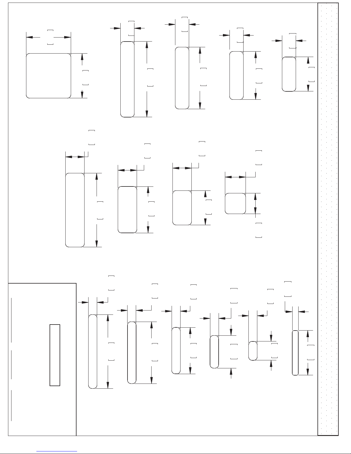
1 x 2
1 x 4
1 x 5
1 x 6
1 x 3
1/2 x 4
5/4 x 6
5 1/2"
139.7
1"
25.4
11.1
.44
82.6
3 1/4"
4 x 4
3 1/2"
88.9
3 1/2"
88.9
4 1/2"
114.3
5/8"
15.9
15.9
5/8" 1 3/8"
34.9
2 x 6
5 3/8"
136.5
1 1/2"
38.1
15.9
5/8" 3 3/8"
85.7
60.3
2 3/8"
15.9
5/8"
1505mm
SOLO)WAVE DESIGN WOOD PROFILES
LENGTH CONVERSION
For example:
1 inch = 25.4mm
BOARD LENGTH 59¼ (59.25) inches
59.25 inches x 25.4mm =
Dimensions in brackets
[mm] represent millimetres.
5/4 x 4
3 1/2"
88.9
1"
25.4
5 3/8"
136.5
5/8"
15.9
2 x 4
3 3/8"
85.7
1 3/8"
34.9
5/4 x 5
4 1/2"
114.3
1"
25.4 2 x 3
2 1/2"
63.5
1 3/8"
34.9
5/4 x 3
63.5
2 1/2"
25.4
1"
2
x 2
1 1/2"
38.1
1 1/2"
38.1
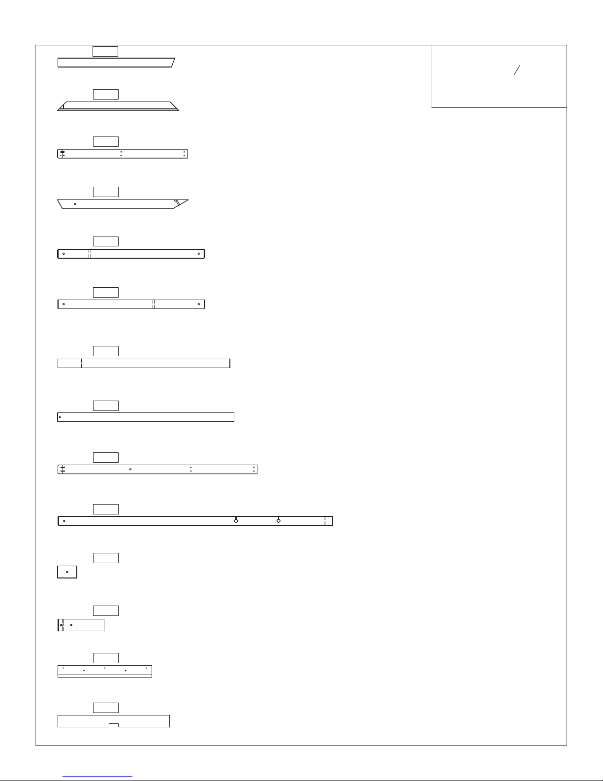
4 pc. -
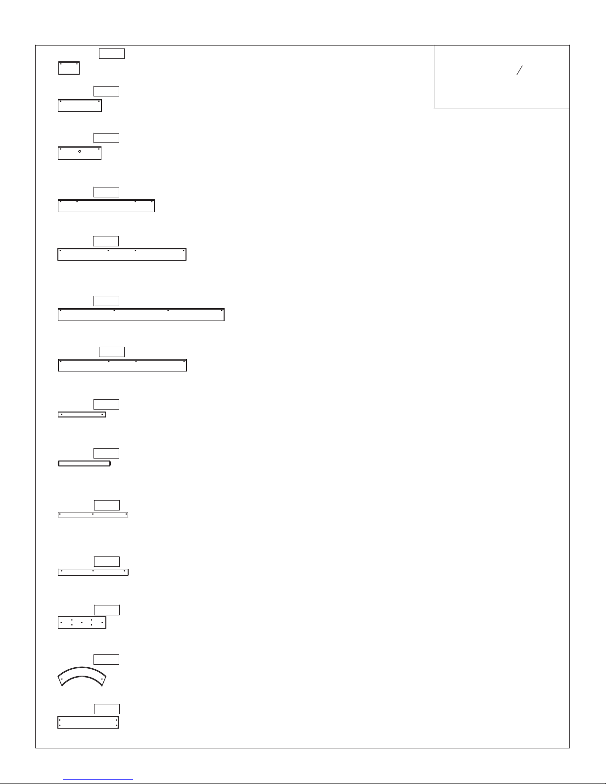
Part Identification (Reduced Part Size) Part Identification (Reduced Part Size) Part Identification (Reduced Part Size)
- Gable Side 1 x 4 x 13 23/32 "‐Box4‐3602419
2419
2409 3632409
"‐Box3‐
Window Trim 1 x 2 x 13 3/8
-
6 pc. -
1 pc. -
-
3632413
"‐Box3‐
CE Siding 3/8 x 3 1/2 x 46 5/8
2413
1852 3631852
"‐Box3‐
CE Siding 3/8 x 3-1/2 x 36
-6 pc. -
2376 3632376
"‐Box3‐
CE Siding 3/8 x 3 1/2 x 27
-
7 pc. -
2430 3632430
"‐Box3‐
Clock Siding 3/8 x 3 1/2 x 12 1/8
-
3632411
"‐Box3‐
- CE Siding 3/8 x 3 1/2 x 5 7/8
2411
10 pc. -
3632412
"‐Box3‐
- CE Siding 3/8 x 3 1/2 x 12 1/8
2412
7 pc. -
1 pc. -
2384 3632384
"‐Box3‐
Post Support 1 x 4 x 13 3/8
-
4 pc. -
1808 3641808
"‐Box2‐
Short Trim 1 x 2 x 19-5/8
-
1 pc. -
2365 3632365
"‐Box4‐
Bottom Top Trim 1 x 2 x 14 5/8
-
2 pc. -
3602421
"‐Box3‐
Part Identification (Reduced Part Size)
Cedar Roofing 3/8 x 3 1/2 x 49 1/2
-2421
1 x 5
1 x 4
1 x 2
x 4
½
Nominal Size
16
⅝" x 4½"
⅝" x 3⅜"
⅝" x 1⅜"
" x 3¼"
7
Actual Size
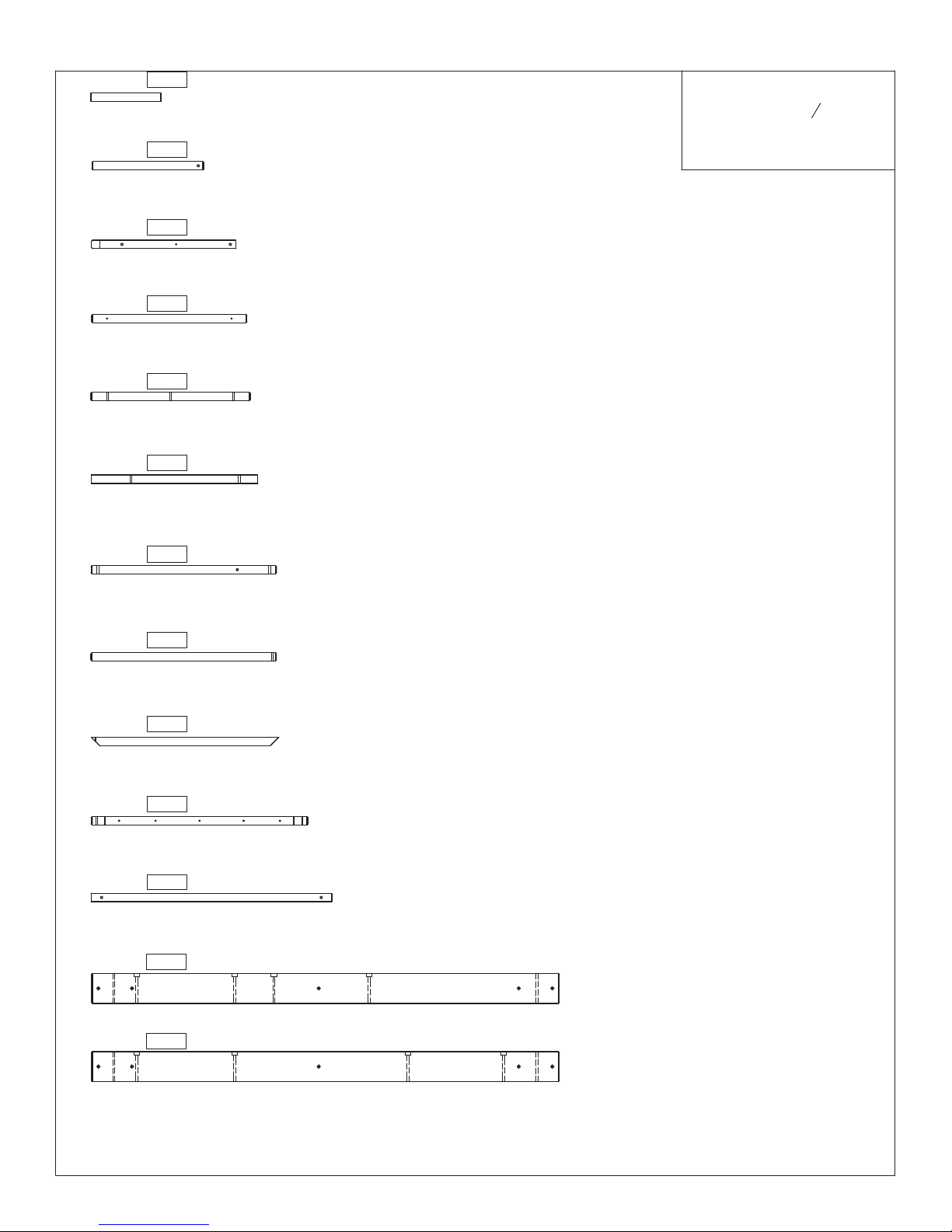
20 pc. -
1870 3641870
"‐Box2‐
Trim Short 1 x 2-1/2 x 19-5/8
-
6 pc. -
2 pc. - 0850 - CE Wall Board 1 x 4 x 17 "‐Box3‐3630850

Part Identification (Reduced Part Size) Part Identification (Reduced Part Size) Part Identification (Reduced Part Size)
4 pc. - 2415 - Cedar Floor Board 1 x 4 x 38 3/4 "‐Box3‐3632415
3 pc. - 0304 - CE Floor Board 1 x 4 x 32-1/2 "‐Box4‐3630304
7 pc. - 5265 - Cedar Wall 1 x 4 x 28 "‐Box4‐3635265
2 pc. - 2358 - A Frame Roof End 1 x 4 x 27 3/4 "‐Box3‐3632358
1 pc. - 2378 - Lower Window 1 x 4 x 27 "‐Box2‐3632378
4 pc. - 1858 - Short Wall Support 1 x 4 x 24-1/4 "‐Box4‐3641858
1 pc. - 2405 - Wall Board 1 x 4 x 25 7/8 "‐Box3‐3632405
2 pc. - 2359 - A Frame Top Side 1 x 4 x 49 3/4 "‐Box4‐3632359
1 pc. - 2422 - Lower Back 1 x 4 x 46 1/2 "‐Box4‐3632422
1 pc. - 2144 - Lower Bench 1 x 4 x 38 7/8 "‐Box4‐3632144
1 pc. - 1502 - Wall Support 1 x 4 x 38-1/4 "‐Box2‐3641502
Part Identification (Reduced Part Size)
Nominal Size
½ x 4
1 x 2
1 x 4
1 x 5
Actual Size
7
16" x 3¼"
⅝" x 1⅜"
⅝" x 3⅜"
⅝" x 4½"
1 pc. - 2354 - A Frame Lower Side 1 x 4 x 48 5/16 "‐Box4‐3632354
2 pc. - 2408 - Wall Support 1 x 4 x 49 3/4 "‐Box4‐3632408
1 pc. - 0353 - MK Ground 1 x 4 x 55-1/4 "‐Box3‐3640353

Part Identification (Reduced Part Size) Part Identification (Reduced Part Size) Part Identification (Reduced Part Size)
1 pc. - 2380 - Middle Front 1 x 5 x 46 5/8 "‐Box2‐3632380
1 pc. - 2416 - Cedar Gap Board 1 x 5 x 38 3/4 "‐Box2‐3632416
2 pc. - 1853 - Cedar Gap Board 1 x 5 x 38-3/4 "‐Box2‐3631853
3 pc. - 1851 - Cedar Floor Board 1 x 5 x 38-3/4 "‐Box2‐3631851
4 pc. - 0348 - SL Ground 1 x 5 x 38-1/4 "‐Box2‐3640348
2 pc. - 2406 - Wall Board 1 x 5 x 19 3/4 "‐Box2‐3632406
2 pc. - 2387 - Side Arch 1 x 5 x 38 1/4 "‐Box4‐3632387
1 pc. - 2372 - Front Ground 1 x 5 x 88 "‐Box2‐3632372
1 pc. - 2423 - A Frame Floor D 1 x 5 x 60 11/32 "‐Box2‐3632423
2 pc. - 2391 - Top Front Back 1 x 5 x 46 5/8 "‐Box2‐3632391
2 pc. - 2371 - Floor End 1 x 5 x 38 7/8 "‐Box2‐3632371
Part Identification (Reduced Part Size)
Nominal Size
½ x 4
1 x 2
1 x 4
1 x 5
Actual Size
7
16" x 3¼"
⅝" x 1⅜"
⅝" x 3⅜"
⅝" x 4½"
1 pc. - 2395 - SW Ground 1 x 5 x 87 7/8 "‐Box2‐3632395
2 pc. - 2418 - Gable Top 1 x 6 x 19 "‐Box3‐3602418
2 pc. - 0606 - CE Access Board 1 x 6 x 19 3/4 "‐Box2‐3630606

Part Identification (Reduced Part Size) Part Identification (Reduced Part Size) Part Identification (Reduced Part Size)
1 pc. - 2425 - A Frame Floor B 1 x 6 x 71 3/8 "‐Box2‐3632425
1 pc. - 2424 - A Frame Floor C 1 x 6 x 65 55/64 "‐Box2‐3632424
1 pc. - 2414 - Cedar Floor Board 1 x 6 x 38 3/4 "‐Box2‐3632414
4 pc. - 2330 - Rock Board A 1 x 6 x 23-1/2 "‐Box2‐3632330
5 pc. - 2257 - Rock Board B 1 x 6 x 23-1/2 "‐Box2‐3632257
2 pc. - 2368 - A Frame Floor 1 x 6 x 20 11/16 "‐Box2‐3632368
1 pc. - 0702 - CE Wall Boards 1 x 6 x 23-1/2 "‐Box2‐3630702
2 pc. - 2105 - Bench Post 5/4 x 4 x 14 "‐Box3‐3632105
1 pc. - 2404 - Tunnel Top Cross 5/4 x 3 x 16 1/2 "‐Box4‐3632404
1 pc. - 2367 - Door Stop 5/4 x 2 x 50 "‐Box2‐3632367
1 pc. - 2393 - A Frame Floor A 1 x 6 x 76 27/32 "‐Box3‐3632393
Part Identification (Reduced Part Size)
Nominal Size
½ x 4
1 x 2
1 x 4
1 x 5
Actual Size
7
16" x 3¼"
⅝" x 1⅜"
⅝" x 3⅜"
⅝" x 4½"
1 pc. - 4909 - SW Block 5/4 x 4 x 3 1/2 "‐Box3‐3654909
2 pc. - 2113 - Gusset II 5/4 x 4 x 18 1/2 "‐Box3‐3632113
1 pc. - 0822 - Ladder Bottom 5/4 x 4 x 20 "‐Box3‐3640822

Part Identification (Reduced Part Size) Part Identification (Reduced Part Size) Part Identification (Reduced Part Size)
1 pc. - 1862 - SW Support 5/4 x 4 x 46-1/2 "‐Box4‐3641862
1 pc. - 0790 - Floor Joist 5/4 x 4 x 46-1/2 "‐Box4‐3640790
1 pc. - 2398 - Tunnel Left End 5/4 x 4 x 25 7/8 "‐Box3‐3632398
1 pc. - 2400 - Tunnel Rail 5/4 x 4 x 24 7/32 "‐Box3‐3632400
1 pc. - 2392 - Tunnel Arch 5/4 x 4 x 23 1/2 "‐Box3‐3632392
4 pc. - 2360 - A Frame Tread 5/4 x 4 x 22 1/8 "‐Box4‐3632360
1 pc. - 2401 - Tunnel Right End 5/4 x 4 x 23 7/16 "‐Box3‐3632401
1 pc. - 2363 - Bench 5/4 x 6 x 41 "‐Box3‐3632363
1 pc. - 2370 - Floor Back 5/4 x 5 x 46 3/4 "‐Box2‐3632370
1 pc. - 2355 - A Frame Lower Side B 5/4 x 4 x 48 5/16 "‐Box4‐3632355
1 pc. - 2350 - Front Floor 5/4 x 4 x 46 3/4 "‐Box4‐3632350
Part Identification (Reduced Part Size)
Nominal Size
½ x 4
1 x 2
1 x 4
1 x 5
Actual Size
7
16" x 3¼"
⅝" x 1⅜"
⅝" x 3⅜"
⅝" x 4½"
1 pc. - 0376 - Table Top 5/4 x 6 x 32 "‐Box2‐3640376
1 pc. - 2389 - SW Back 5/4 x 6 x 46 5/8 "‐Box3‐3632389
1 pc. - 2397 - Tunnel Joist 2 x 3 x 18 1/4 "‐Box3‐3632397
Part Identification (Reduced Part Size) Part Identification (Reduced Part Size) Part Identification (Reduced Part Size)
1 pc. - 2388 - SL Upright 2 x 3 x 48 1/2 "‐Box2‐3632388
1 pc. - 2381 - MK Mount 2 x 3 x 41 1/2 "‐Box2‐3632381
4 pc. - 2361 - A Frame Upright 2 x 3 x 41 1/2 "‐Box2‐3632361
2 pc. - 0369 - Lower Diagonal 2 x 3 x 37 "‐Box2‐3640369
1 pc. - 2362 - Back Tunnel Support 2 x 3 x 36 39/64 "‐Box2‐3632362
1 pc. - 2140 - Short Upright 2 x 3 x 33 "‐Box4‐3632140
4 pc. - 2394 - Roof Support 2 x 3 x 34 1/4 "‐Box3‐3632394
4 pc. - 2364 - Block 2 x 4 x 13 "‐Box2‐3632364
2 pc. - 2382 - MK Post 2 x 3 x 77 1/2 "‐Box2‐3632382
1 pc. - 2373 - Front Tunnel Support 2 x 3 x 56 15/64 "‐Box4‐3632373
1 pc. - 2377 - Lower Post 2 x 3 x 49 3/4 "‐Box2‐3632377
Part Identification (Reduced Part Size)
Nominal Size
½ x 4
1 x 2
1 x 4
1 x 5
Actual Size
7
16" x 3¼"
⅝" x 1⅜"
⅝" x 3⅜"
⅝" x 4½"
1 pc. - 4919 - SW Rail Block 2 x 4 x 5-3/8 "‐Box3‐3644919
1 pc. - 2396 - Tunnel Corner Support 2 x 4 x 26 1/2 "‐Box4‐3632396
1 pc. - 2403 - Tunnel Top 2 x 4 x 31 19/32 "‐Box4‐3632403

1 pc. -
Part Identification (Reduced Part Size) Part Identification (Reduced Part Size) Part Identification (Reduced Part Size)
- Short Joist 2 x 2 x 11 1/2 "‐Box2‐3632386
2386
1565 3641565
"‐Box4‐
MK Rail Short 2 x 4 x 50
-
2 pc. -
1856 3641856
"‐Box4‐
SW Upright 2 x 4 x 48-5/16
-
1 pc. -
2420 3602420
"‐Box4‐
Bottom Gable 2 x 4 x 41
-
2 pc. -
2353 3632353
"‐Box4‐
A Frame Floor Support 2 x 4 x 36 31/32
-
2 pc. -
2366 3632366
"‐Box4‐
Centre Post 2 x 4 x 32 3/4
-
1 pc. -
2390 3632390
"‐Box4‐
SW Mount 2 x 4 x 34 1/2
-
1 pc. -
1863 3641863
"‐Box3‐
SW Post 2 x 4 x 86-11/16
-
2 pc. -
2352 3632352
"‐Box3‐
A Frame Access R 2 x 4 x 66 3/16
-
1 pc. -
2351 3632351
"‐Box3‐
A Frame Access L 2 x 4 x 66 3/16
-
1 pc. -
3632410
"‐Box2‐
Part Identification (Reduced Part Size)
Right Access 2 x 4 x 58
-2410
1 x 5
1 x 4
1 x 2
x 4
½
Nominal Size
16
⅝" x 4½"
⅝" x 3⅜"
⅝" x 1⅜"
" x 3¼"
7
Actual Size
1 pc. -
2356 3632356
"‐Box3‐
A Frame Post 2 x 4 x 66 3/16
-
2 pc. -
2383 3632383
"‐Box2and4‐
Post 2 x 4 x 88
-
4 pc. -
1 pc. - 2374 - Left Access 2 x 4 x 58 "‐Box2‐3632374
Part Identification (Reduced Part Size) Part Identification (Reduced Part Size) Part Identification (Reduced Part Size)
1 pc. - 2399 - Tunnel Post 2 x 2 x 33 1/8 "‐Box4‐3632399
1 pc. - 2375 - Long Joist 2 x 2 x 29 3/4 "‐Box4‐3632375
2 pc. - 2407 - Wall Joist 2 x 2 x 28 1/2 "‐Box4‐3632407
1 pc. - 2357 - A Frame Ridge 2 x 2 x 27 3/4 "‐Box4‐3632357
1 pc. - 2379 - Mid Joist 2 x 2 x 25 13/16 "‐Box4‐3632379
2 pc. - 0620 - SL Brace 2 x 2 x 12-1/2 "‐Box3‐3640620
2 pc. - 2385 - Roof Upright 2 x 2 x 20 "‐Box2‐3632385
1 pc. - 1825 - Back Beam 2 x 6 x 83-5/8 "‐Box3‐3631825
1 pc. - 1868 - Table Support 2 x 2 x 38-3/4 "‐Box4‐3641868
2 pc. - 2417 - Joist 2 x 2 x 33 1/2 "‐Box4‐3602417
4 pc. - 2402 - Tunnel Spindle 2 x 2 x 33 1/8 "‐Box2‐3632402
Part Identification (Reduced Part Size)
Nominal Size
½ x 4
1 x 2
1 x 4
1 x 5
Actual Size
7
16" x 3¼"
⅝" x 1⅜"
⅝" x 3⅜"
⅝" x 4½"
1 pc. - 0795 - Side Joist 2 x 2 x 43 "‐Box4‐3640795
1 pc. - 1826 - Front Beam 2 x 6 x 83-5/8 "‐Box3‐3631826

1 pc. -
Part Identification (Reduced Part Size) Part Identification (Reduced Part Size) Part Identification (Reduced Part Size)
- Door Panel Green 1-3/16 x 16-3/8 x 43-5/16 "‐Box4‐3608197
8197
0318 3650318
"‐Box1‐
1-1/4 x 1-1/2 x 14
- Ground Stake
7 pc. -
3681578
"‐Box1‐
Part Identification (Reduced Part Size)
1-1/8 x 15-7/8
- Tennon Dowel578
1 x 5
1 x 4
1 x 2
x 4
½
Nominal Size
16
⅝" x 4½"
⅝" x 3⅜"
⅝" x 1⅜"
" x 3¼"
7
Actual Size
3 pc. -
6 pc. - 858 - Tennon Dowel 1-1/8 x 18-5/8 "‐Box1‐3681858

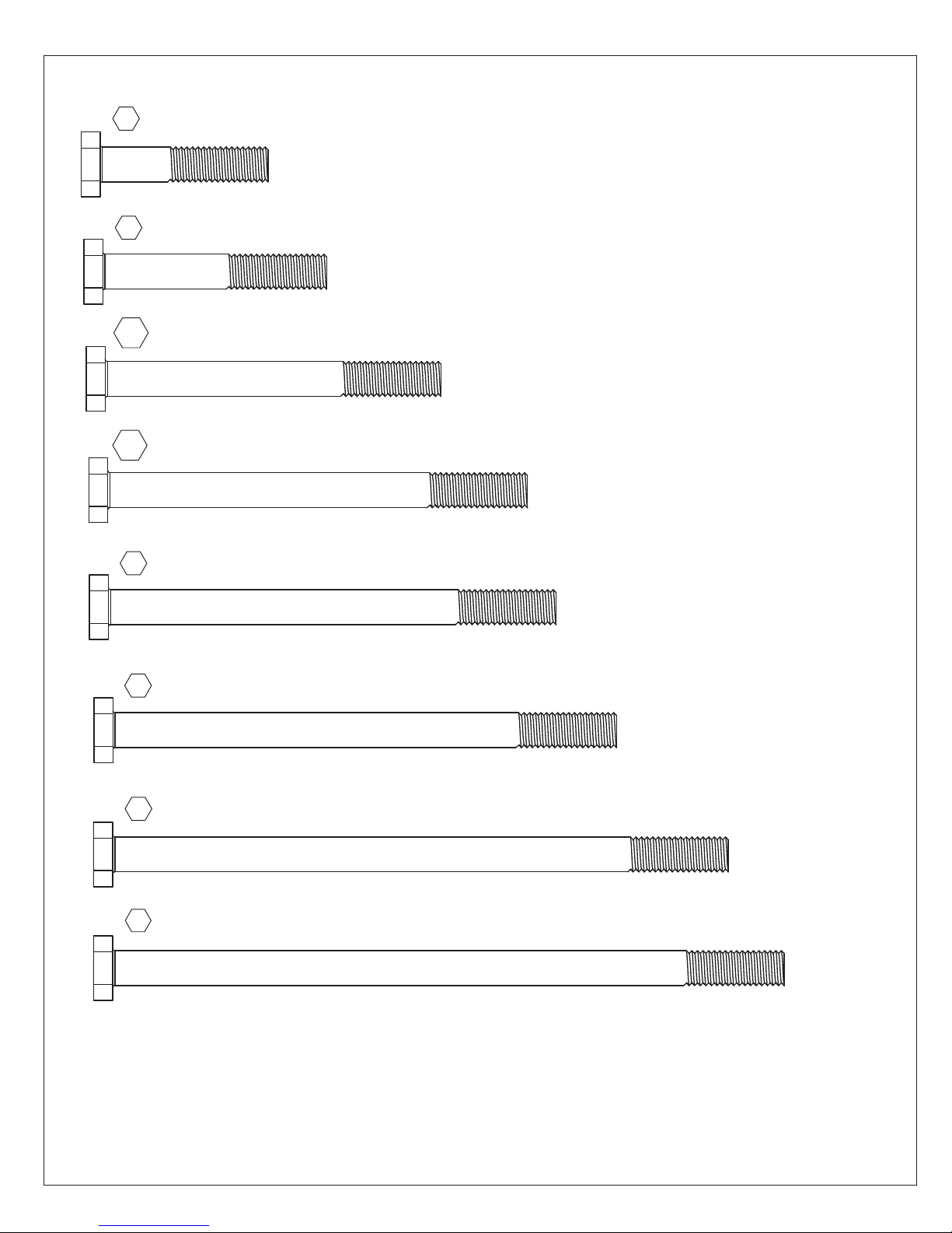
Hardware Identification(ActualSize)
1pc. H8 -HexBolt1/4x4-1/4"-(9277241)
7pc. LS3 -LagScrew1/4x3"-(9262230)
4pc. H1 -HexBolt1/4x1-1/2"-(9277212)
9pc. H3 -HexBolt1/4x2-1/2"-(9277222)
35pc. H2 -HexBolt1/4x2"-(9277220)
10pc. H11 -HexBolt1/4x2-3/4"-(9277223)
5pc. H12 -HexBolt1/4x3"-(9277230)
9pc. H5 -HexBolt1/4x4-1/2"-(9277242)
4pc. H7 -HexBolt1/4x5-1/2"-(9277252)
15pc. H4 -HexBolt1/4x4"-(9277240)
12pc. LS1 -LagScrew1/4x1-1/2"-(9262212)
2pc. LS2 -LagScrew1/4x2-1/2"-(9272222) 1pc. LS4 -LagScrew1/4x4"-(9262240)
Hardware Identification(ActualSize)
4pc. G1 -HexBolt5/16x1-1/2"-(9277312)
7pc. G5 - HexBolt5/16x4-1/2"-(9277342)
3pc. G4 -HexBolt5/16x4"-(9277340)
2pc. G8 -HexBolt5/16x2"-(9277320)
2pc. Z-HexBolt5/16x6"-(9277360)
4pc. G7 -HexBolt5/16x5-1/2"-(9277352)
2pc. G10 -HexBolt5/16x3"-(9277330)
4pc. G21 -HexBolt5/16x3-3/4"-(9277333)

10pc. S16 -PanScrew#6x1"-(9264010)
3pc. S8 -PanScrew#12x3/4"-(9264603)
34pc. S5 -PanScrew#8x1/2"-(9264504)
Hardware Identification(ActualSize)
12pc. LN2 -5/16"LockNut- (9283300)
20pc. S15 -WoodScrew#8x1-3/4"-(52043513)
102pc. LW1 -1/4"LockWasher-(9253200)
15pc. FW0 -3/16"FlatWasher-(9251100)
172pc. S0/S22 -TrussScrew#8x7/8"-(9229505)
10pc. FW3 -#8FlatWasher-(9251500)
28pc. S7 -PanScrew#12x2"-(9264620)
10pc. PB2 -PanBolt1/4x1-1/4"-(9274211)
20pc. LW2 -5/16"LockWasher-(9253300)
20pc. TN2 -5/16"T-Nut- (9285300)
18pc. S6 -PanScrew#12x1"-(9264610)
9pc. BN1 -1/4"BarrelNut-(9248200)
4pc. S18 -WoodScrew#6x1"-(9260910)
93pc. TN1 -1/4"T-Nut-(9285200)
72pc. S1 -WoodScrew#8x1-1/8"-(52042514)
263pc. S2 -WoodScrew#8x1-1/2"-(52042512)
115pc. FW1 -1/4"FlatWasher-(9251200)
44pc. FW2 -5/16"FlatWasher-(9251300)
18pc. S4 -WoodScrew#8x3"-(52042530)
75pc. S3 -WoodScrew#8x2-1/2"-(52042522)
65pc. S10 -PanScrew#8x1"-(9264510)
56pc. S13 -PanScrew#6x5/8"-(9264990)
Table of contents
Other Big Backyard Baby Swing manuals

Popular Baby Swing manuals by other brands

Safety 1st
Safety 1st 21070C user guide

Loll Designs
Loll Designs GO PORCH SWING installation instructions

M&M
M&M JOHNY TRACTOR AND FRIENDS Installation, Operation & www.mandmsalesinc.com Maintenance Instructions

mothercare
mothercare travel swing user guide

baby joy
baby joy BC10089 user manual

ingenuity
ingenuity Simple Comfort Cradling Swing manual


