Bigab 22-27 User manual

22-27
© V7.1-2015W42–en Fors MW Ltd www.forsmw.com 1
Table of Contents
1
INTR DUCTI N ...................................................................................................... 2
Company presentation .......................................................................................... 2
Product presentation ............................................................................................. 2
2
TECHNICAL SPECIFICATI NS .................................................................................. 3
3
DIMENSI NAL DIAGRAMS ..................................................................................... 4
4
GENERAL DESCRIPTI N .......................................................................................... 5
5
MAIN C MP NENTS.............................................................................................. 6
6
SAFETY FEATURES ................................................................................................ 15
Safety support ...................................................................................................... 15
Location of the decals on the trailer .................................................................... 15
Presentation of decals ......................................................................................... 16
7
C UPLING/UNC UPLING THE TRAILER ............................................................... 21
Safety aspects when coupling/uncoupling .......................................................... 21
C UPLING T TRACT R ....................................................................................... 22
8
DRIVING THE TRAILER .......................................................................................... 23
Safety aspects when driving ................................................................................ 23
R AD DRIVING INSTRUCTI NS ............................................................................ 24
Load on towing eyelet and coupling .................................................................... 25
Working under extreme conditions ..................................................................... 26
EXCHANGE MECHANISM ..................................................................................... 27
9
EXCHANGE PERATI N ....................................................................................... 28
Safety aspects during exchange operation .......................................................... 28
Exchange procedure ............................................................................................ 29
10
TIPPING PERATI N ............................................................................................ 32
11
WIRING DIAGRAM ................................................................................................ 33
12
HYDRAULICS CHART ............................................................................................. 36
13
CARRYING UT SERVICE/MAINTENANCE ............................................................ 37
14
MAINTENANCE/SERVICE ...................................................................................... 39
15
SPARE PARTS ........................................................................................................ 46
16
TR UBLESH TING ............................................................................................. 53
17
EC DECLARATI N (sample) .................................................................................. 54
C NTACT INF RMATI N:
Factory:
AS F RS MW
Tule 30
765 05 Saue
Estonia
Tel: + 372 679 00 00
Fax: + 372 679 00 01
E-mail:
Aftermarket:
We speak English and Swedish.
FMW Farma Norden AB
Hornsväg 2
SE-605 97 Norrköping
Sweden
Tel: + 46 (0) 11 657 70
Fax: + 46 (0) 11 283 70
E-mail:
aftermarket@forsmw.com

22-27
© V7.1-2015W42-en Fors MW Ltd www.forsmw.com
2
1INTRODUCTION
Stringent demands are placed on manufacturers to comply with the directives for
the product they produce. This product is covered by the Machinery Directive and
the CE marking indicates that it meets the requirements of the Directive. n delivery
of a product, the dealer is required to provide operating instructions for the product.
Company presentation
AS F RS MW was established in Estonia in 1992. The company develops,
manufactures, markets and sells, via dealers, its three market-leading brands. These
are BIGAB hook lift trailers and dump trailers, FARMA lumber trailers and cranes, and
NIAB tractor processors. The company comprises the parent company AS F RS MW,
as well as the subsidiary companies Farma Norden AB (Norrköping, Sweden) and
ForsMW/China. You can find out more about the product you have selected and our
20-year journey by visiting our websitewww.forsmw.com and our blog
www.forsmw.blogspot.com
Prod ct presentation
The BIGAB hook lift exchange system includes a range of models, all offering the
same high level of versatility. A wide and varied range of accessories is also available.
The versatility lies in its ability to handle different kinds of loads on one and the same
chassis. You will find your BIGAB indispensible for a wide range of tasks.
The 22 – 27 is our largest hook lift trailer. Simple, impressive and powerful are all
fitting ways to describe the BIGAB 22 – 27. This is the ideal trailer for transporting
particularly heavy loads. For your safety, it is extremely important that you follow
the instructions in this instruction manual for your BIGAB model.
22-27
© V7.1-2015W42-en Fors MW Ltd www.forsmw.com
3
2TECHNICAL SPECIFICATIONS
Hook lift trailer 22-27
Frame: Rectangular sections 300*100
Bogie: Parabolic sprung triple axles Axle distance 1525 mm
H bs: 130*130, 10 bolts
Tyres: 560/60-22.5
Brakes:
Hydraulic drum
*
Depending on
market 406*120 on 6 wheels
Towing eyelet: For hitch hook
Stabiliser legs: Manual Yes
Light system: 12 volt Yes
Tractor hydra lics: *For brakes
Pressure & return, 1 single
-
action brake/
1 double-action with floating position
Oil vol me: With full system 23 l
Oil vol me: Press 89 l, draw 66 l
Oil flow: 60-120 l/min
Max working press re: Max. 22 MPa
Tipping angle: 50 degrees
Chassis weight (±1%): Standard equipped 6600 kg
Chassis length (±50mm): 7550 mm
Distance eyelet to centre tridem (±20mm): Centered tridem axle 5155 mm
Distance eyelet to gro nd s rface: Min. 475 mm
Height nloaded: 1330mm excl. load carrier frame
Width across wheels (±30mm): 2590 mm
Bridge length: 5700-6500 mm
Total weight (±1%): 28 600 kg
Max. load incl. bridge: tipping (±1%): 22 000 kg
Max. load incl. bridge: roll on/roll off (±1%): 21 000 kg
Load on towing eyelet:
Depending on the position of the trailer bed 2500 – 3500 kg
Max. speed 40 km/h
REF: 150923
/REF:150706

22-27
© V7.1-2015W42-en Fors MW Ltd www.forsmw.com
4
3DIMENSIONAL DIAGRAMS
22-27
© V7.1-2015W42-en Fors MW Ltd www.forsmw.com
5
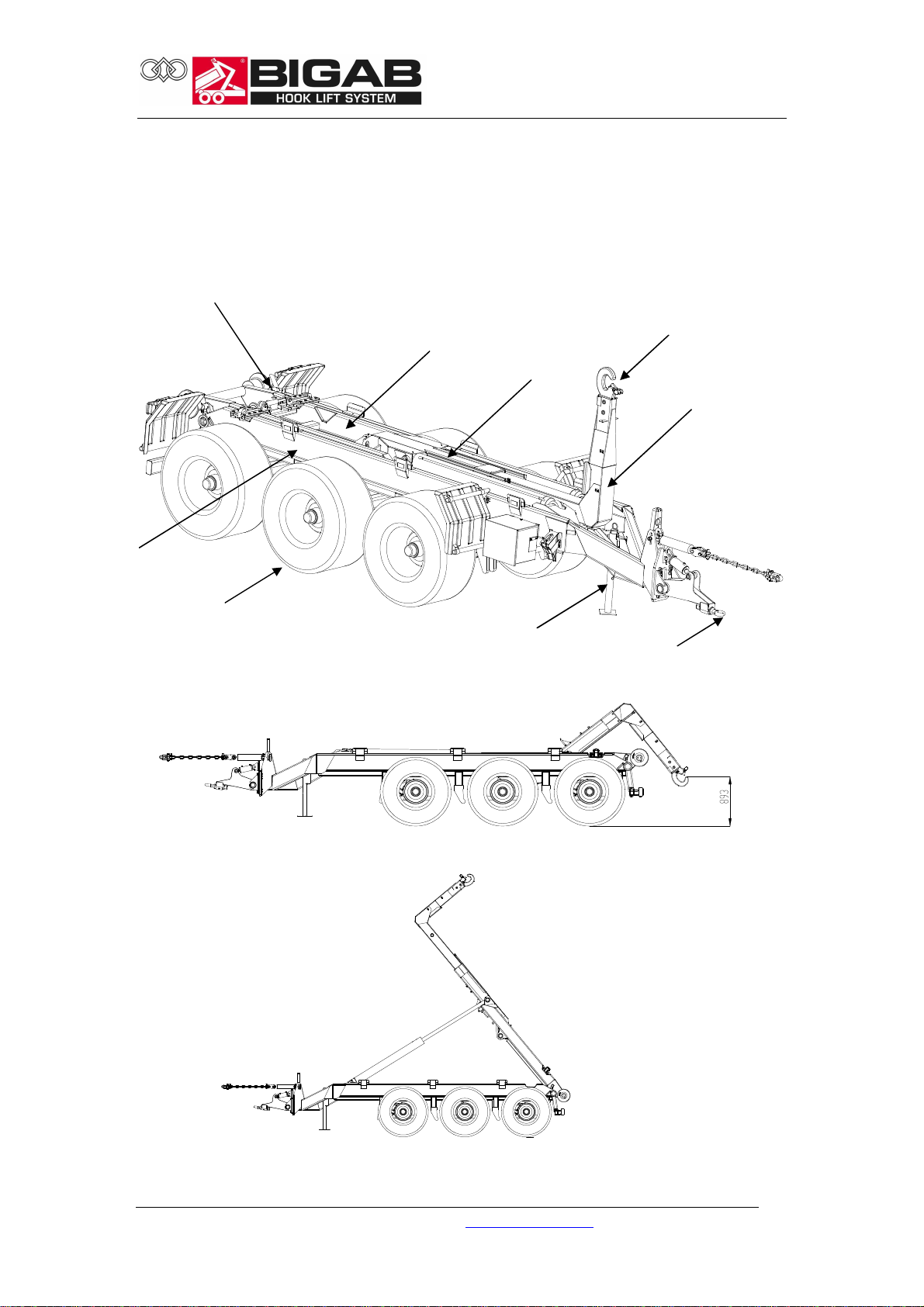
4GENERAL DESCRIPTION
The trailer is steady when used for both tipping and exchanging. The trailer is
equipped with a torsional parabolic spring bogie on three axles with brakes on all
wheels.
Chassi
Hook
Wheels
Rear
frame
Hook
frame
Steering
roller
Stabilise
r leg
Towing
Exchange
position
Tipping
position
Telescop
e
22-27
© V7.1-2015W42-en Fors MW Ltd www.forsmw.com
6
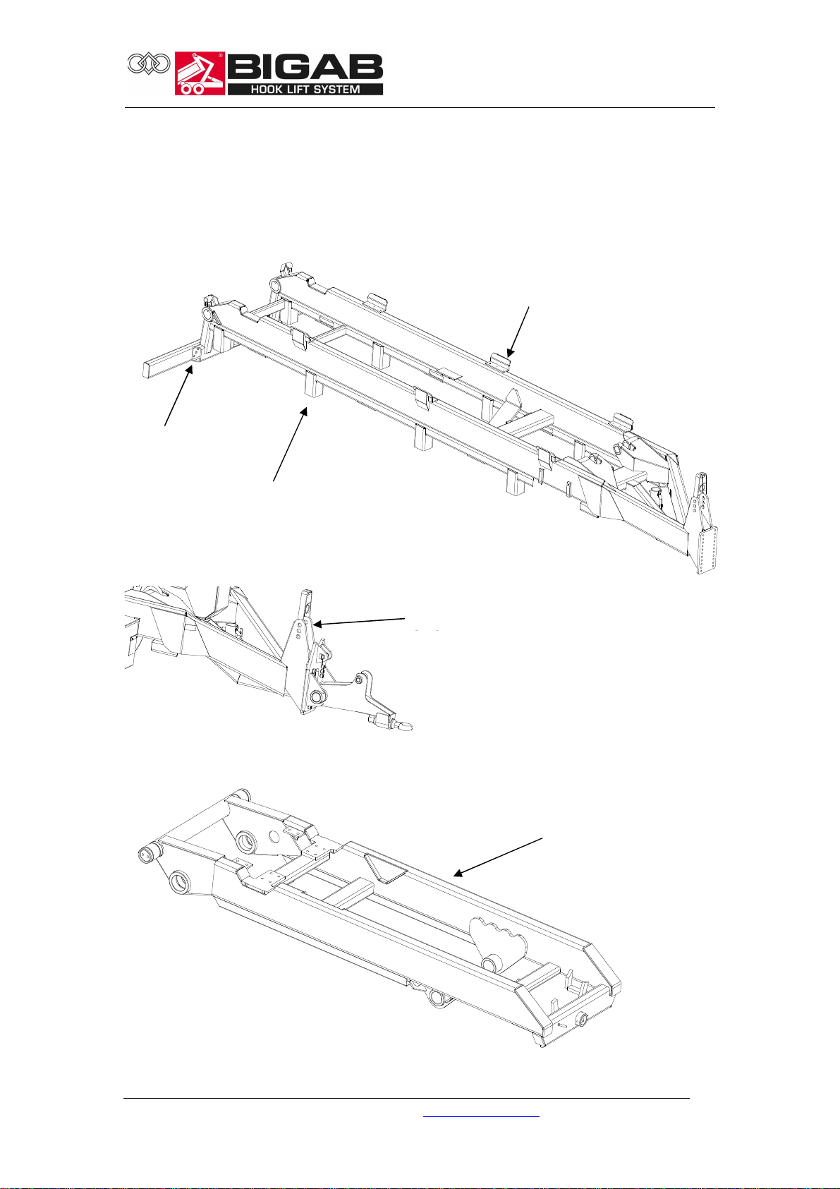
5MAIN COMPONENTS
The trailer comprises the following principal components and functional devices.
Chassis
Rear frame
Rear beam
Suspension
bracket
Side
support
Rear frame
Bracket for frame
lock

22-27
© V7.1-2015W42-en Fors MW Ltd www.forsmw.com
7
Hook frame
Bogie
The trailer is equipped with a powerful sprung tridem bogie with brakes on all six
wheels.
Brake cylinder
Axle with brake
x 3
Sprung tridem
bogie
Hook
Hook
frame
Telescope
Extended tower
1300 mm
Hydraulic cylinder (inside)

22-27
© V7.1-2015W42-en Fors MW Ltd www.forsmw.com
8
Hook
The trailer is equipped with an adjustable hook for two different heights.
Stabiliser leg
The stabiliser leg is designed to support the trailer when not in use. The stabiliser leg
must not be used when the trailer is loaded. The stabiliser leg must be raised and
secured in place with the pin before moving off.
Stabiliser leg
Pin
Chassis
Standard height: 1450
Standard height: 1570

22-27
© V7.1-2015W42-en Fors MW Ltd www.forsmw.com
9
Exchange nit
The unit is designed for
the procedure when switching between
tipping and exchange.
The lever is located in the middle
of the rear frame.
Exchange nit container lock
The trailer is equipped with a
hydraulic container lock
that secures the container to the frame
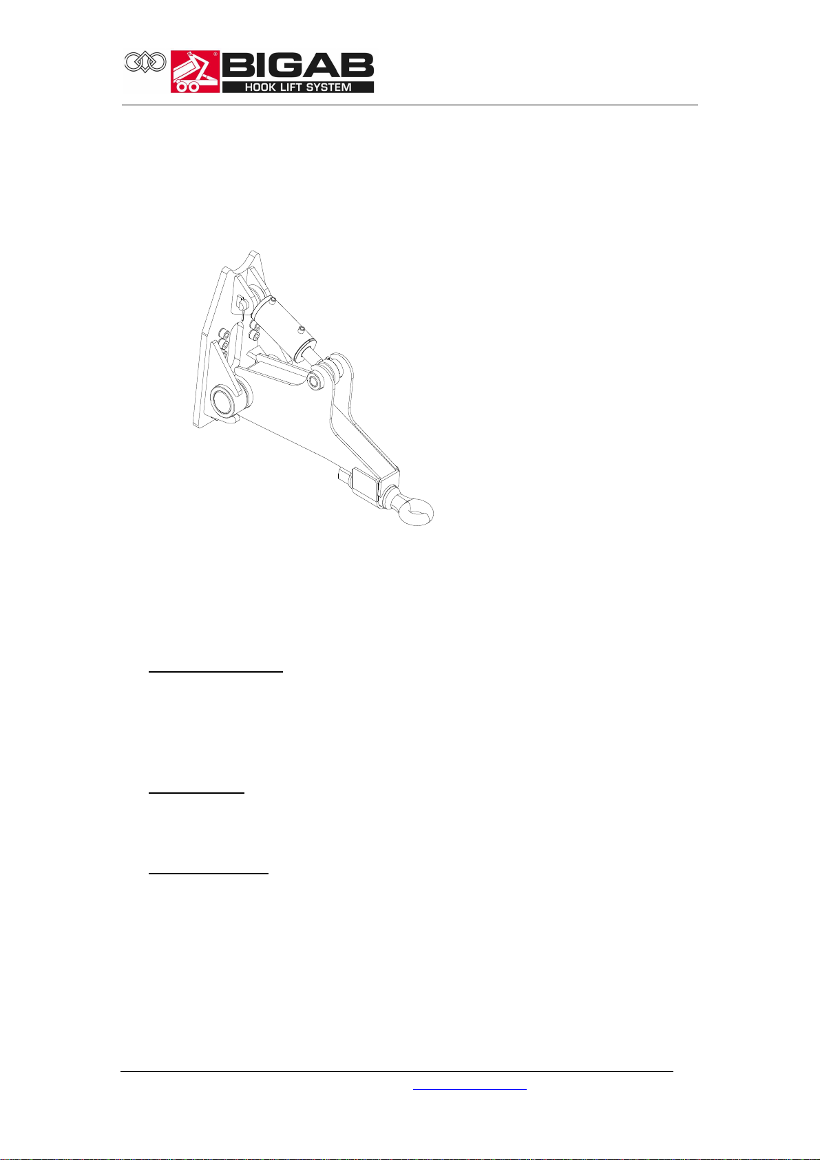
Towing eyelet
The towing eyelet is adapted to the hitch on the towing vehicle. It is extremely
important that the towing eyelet is inspected for defects every time the trailer is
used.
Hydraulic cylinder
Locking bolt
Rear frame
Chassis
Towing eyelet
Hydraulic cylinder
Locking lug
22-27
© V7.1-2015W42-en Fors MW Ltd www.forsmw.com
10
Drawbar
The drawbar is used for coupling other equipment to the trailer. It is also used for
attaching the warning triangle. Note! Do not couple excessively heavy loads to the
drawbar. The maximum permitted trailer weight is 10 tonnes.
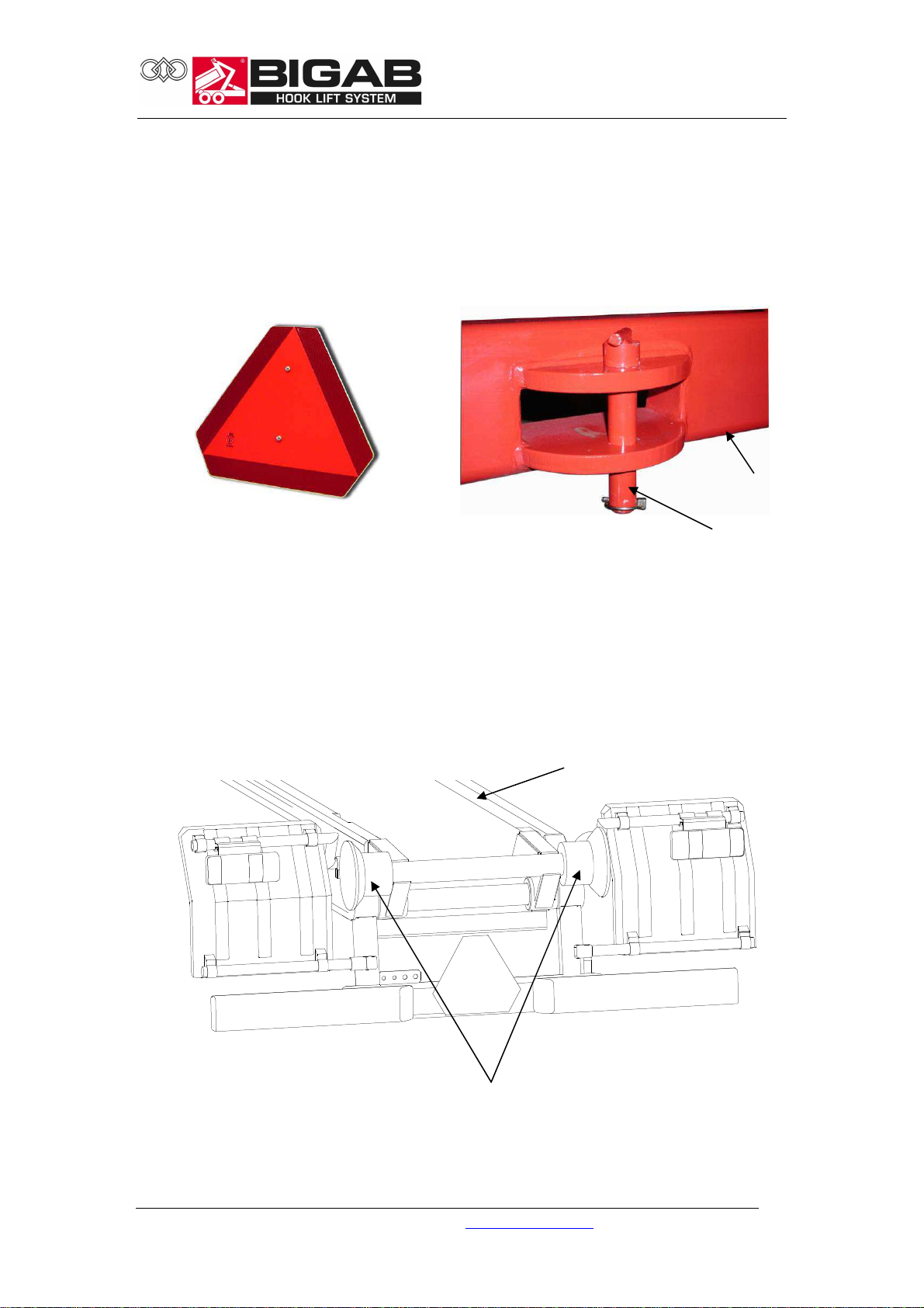
Steering rollers
The steering rollers are designed to guide the bed correctly. The bed frame must be
inside the steering rollers during exchange operations.
Rear beam
Pin
Steering roller Left Right
Chassis

22-27
© V7.1-2015W42-en Fors MW Ltd www.forsmw.com
11
Frame lock
The hydraulic frame lock is used to lock the frame during heavy exchange operations.
When mounting the chain on the tractor for the first time, adjust the length of the
chain so that it is slack when the cylinder is half extended.
When you then tension the cylinder, the pressure relief valve is set at about 100 bar
and it can be adjusted to the size of the tractor.
It is very important to slacken it after exchanging so as not to impede the tractor
during transport.
Frame lock hydraulic
cylinder
Chain to tractor
Manometer
22-27
© V7.1-2015W42-en Fors MW Ltd www.forsmw.com
12
S spended drawbar
Drawbar f nctions
The trailer is equipped with an adjustable drawbar that can be used for the following
three functions. Use the position switch on the control unit to regulate the drawbar.
Select a function and regulate the pressure with the toggle switch.
Suspended drawbar
Set the mode switch to suspension mode and then apply pressure. Watch the
manometer to see how much pressure you apply. The valve has a pressure
limiter that controls the amount of pressure you can apply. Check at regular
intervals during transport that the pressure remains constant.
Fixed drawbar
This function is used to stabilise the trailer when exchanging containers. Set the
mode switch to fixed mode and apply pressure to stabilise the drawbar.
Swinging drawbar
Set the mode switch to swinging mode. No pressure is applied to the drawbar.
22-27
© V7.1-2015W42-en Fors MW Ltd www.forsmw.com
13
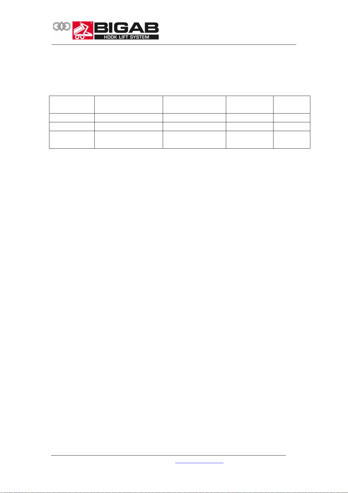
Tyres
List of standard tyres and alternative tyres that are used for the different trailer
models.
Model
Standard tyres Alternative tyres Air press re
(bar)
Speed
(km/h)
22-27 560/60-22.5 3.6 40
445/65R-22.5 5-10 40
650/50R-22.5 TL
10B -70
4.0 40
* The air press re may vary slightly depending on the make of tyre. Contact the tyre
man fact rer for exact air press res.
Hydra lic system
The trailer is equipped with a hydraulic system for the various work operations. For
more information, see the Hydraulics Chart chapter.
Electrical system
The trailer has a 12 volt electrical system. For more information, see the Wiring
Diagram chapter.
Brake system
The trailer is equipped with a hydraulic brake system. A pneumatic brake system is
also available as optional equipment. Note! The hydraulic pressure in the brake lines
should not exceed 16 Mpa. Too much hydraulic pressure can cause the brake arm
cam to go over-centre and lock the brakes.
22-27
© V7.1-2015W42-en Fors MW Ltd www.forsmw.com
14
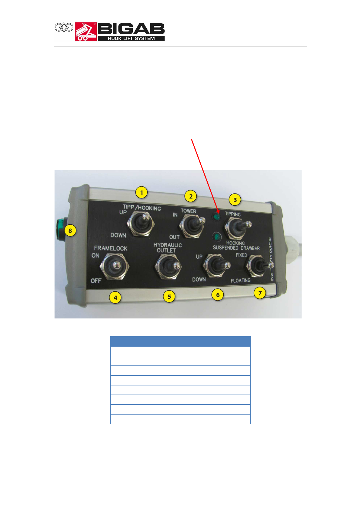
Electric on-off control
The trailer is equipped with a hydraulic system that is operated via a control unit.
With regard to position 3, it is important to run this function until the signal lights
come on. This indicates that the locks have reached their end stop position.
No.
Description
1
Tipping/Exchange
2
Telescope in/out
3
Exchange/tip/container lock
4
Frame lock
5
Hydraulic outlet
6
Suspended drawbar up
-
down
7
Suspended drawbar locked
-
sprung
-
floating
8
n
-
ff
With regard to position 3, it is important to run
this function until the signal lights come on.
This indicates that the locks have reached their
end stop position.

22-27
© V7.1-2015W42-en Fors MW Ltd www.forsmw.com
15
6SAFETY FEATURES
Safety s pport
Always use the safety support when carrying out service work when the trailer bed is
raised. The safety support must not, under any circumstances, be used when the
trailer bed is loaded.
Location of the decals on the trailer
The trailer is marked with various signs relating to safety and information. Check that
all signs are correctly positioned.
Safety support
Chassis
22-27
© V7.1-2015W42-en Fors MW Ltd www.forsmw.com
16
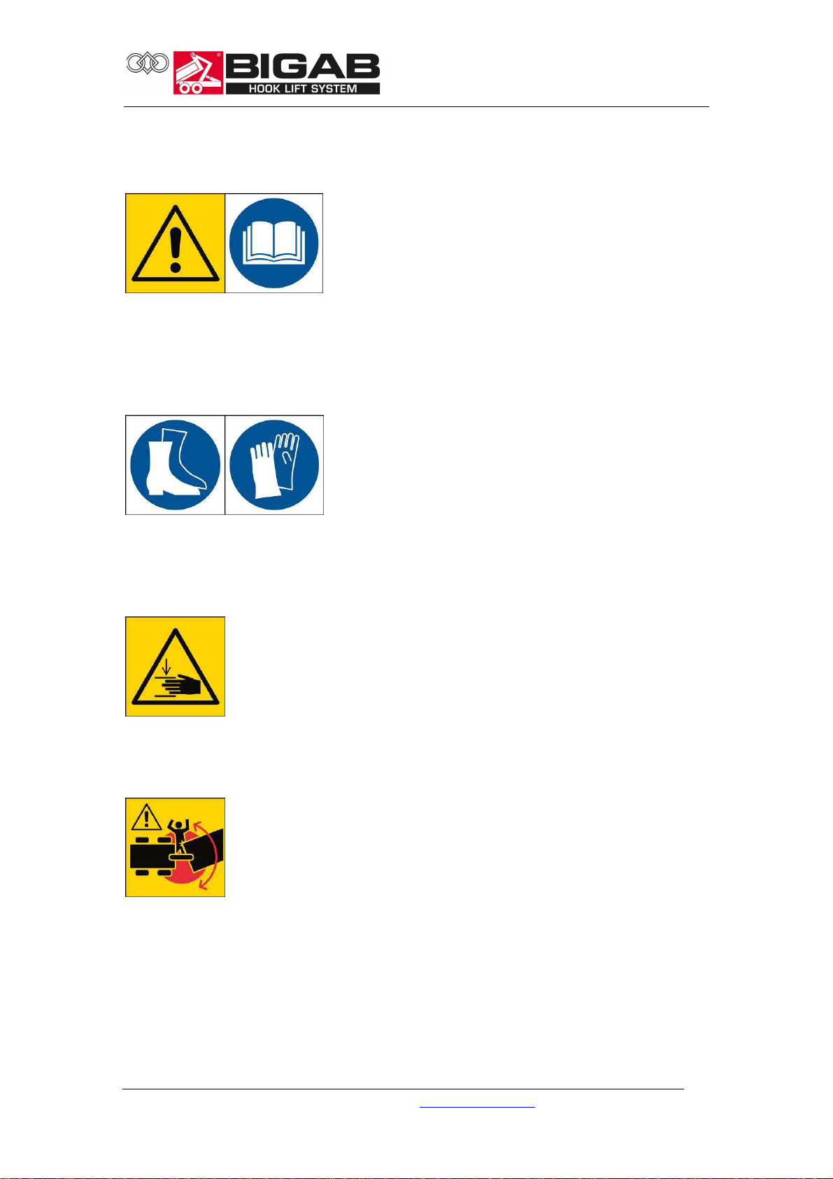
Presentation of decals
WARNING!
Warning triangle and instruction manual decal.
The trailer has a warning triangle next to the instruction manual decal to emphasis
the importance of reading the entire instruction manual carefully before using the
trailer. Failure to observe this may result in serious or fatal injury.
INFORMATION!
Decal for the use of safety equipment.
These decals encourage the use of appropriate safety equipment in order to avoid
injury when using the trailer.
DANGER!
Risk of crushing injuries
There is a risk of trapping and crushing injuries during work and maintenance.
WARNING!
Hazardous area
Standing between the trailer and the towing vehicle when the trailer is being driven,
moved with frame steering or when other functions are activated between the
trailer and towing vehicle, can be potentially fatal. As the driver, you must always
ensure that no one is in the area around the machinery.
22-27
© V7.1-2015W42-en Fors MW Ltd www.forsmw.com
17
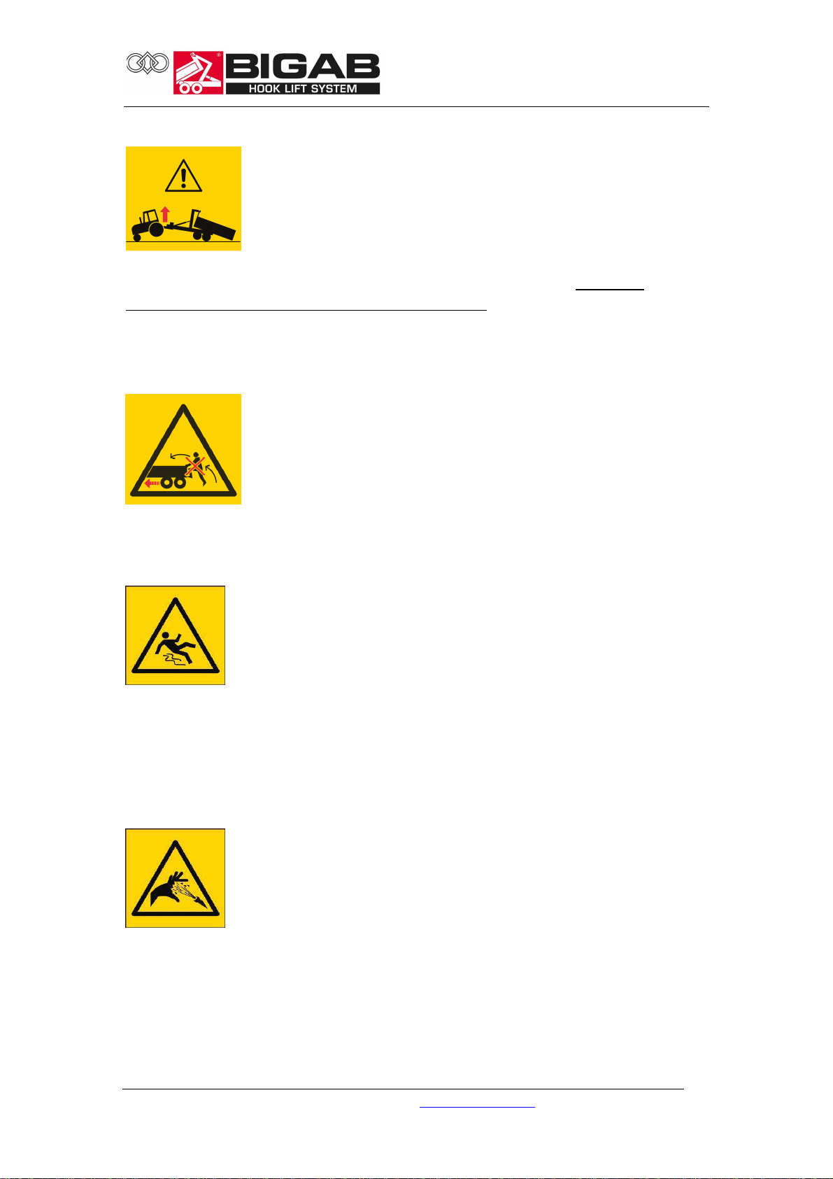
WARNING!
Warning - It is a hazardous movement if the rear end of the tractor lifts
Note! This warning label is included in the delivery of your trailer. It must be
attached in a conspicuous position in the tractor cab. If you would like more of these
labels, they are available to order, free of charge, from our after sales department.
Contact details are printed on the first page in the instruction manual.
WARNING!
It is absolutely forbidden to board the trailer when it is moving
Anyone doing so may be at risk of serious or fatal injury.
WARNING!
Risk of slipping
There is a risk of slipping as the surfaces of the trailer can be slippery due to a
combination of precipitation and oil and/or clay on the surface. The ground around
the trailer can also become slippery, as the tyres can tear up the surface and expose
clay and soil.
DANGER!
Hydraulic fluid under pressure
Hot hydraulic fluid at high pressure levels can occur in the hydraulic system. Take
care when connecting. Replace worn or damaged hoses.

22-27
© V7.1-2015W42-en Fors MW Ltd www.forsmw.com
18
INFORMATION!
Using the exchange unit
Do not operate the exchange unit unless the frame is folded down. During transport
with the trailer, the hook must be folded down in the parking position.
WARNING!
Use the safety support during all service operations
It is absolutely forbidden to lean under a raised frame unless it is secured with the
safety support. Under no circumstances may the trailer be carrying a load or
container when the safety support is being used.
WARNING!
Maximum load
It is absolutely prohibited to load more than the amount your model of trailer is
designed to handle. This can be dangerous for you and your surroundings.

22-27
© V7.1-2015W42-en Fors MW Ltd www.forsmw.com
19
WARNING!
Max. pressure on towing eyelet
Do not load so much that the pressure on the towing eyelet exceeds the permitted
laws and regulations. The trailer is designed for a maximum pressure of 3000 kg on
the towing eyelet. The pressure is largely determined by the way the load is
distributed on the container bridge, and it is the user’s responsibility to ensure that
this is not exceeded.
INFORMATION!
Tyre inspection
The tyres must be tightened and the brakes must be inspected regularly.
INFORMATION!
Lubrication
This decal is used to show the importance of regular lubrication of the trailer.
INFORMATION!
ID- plate

22-27
© V7.1-2015W42-en Fors MW Ltd www.forsmw.com
20
Marking of hydra lics
All of the hydraulic hoses are marked with coloured labels. See the table below for
more detailed information. The functions depend on the configuration of the
hydraulic system.
Hydraulic hose label (example tipping cylinder)
Hose label colors:
•Red - il from pump
•Blue - il to tank
•Yellow - Brake
Marking of the hydraulic hoses
.
No. Colo r F nction
1 Yellow Brakes
26 Red Steering (p)
27 Blue Steering (t)
Table of contents
Other Bigab Utility Vehicle manuals


