Hisun Motors HS750UTV-2 User manual

FOREWORD
Brief introduction to maintenance handbook of HS750UTV-2
The handbook is edited by Technical Center of Chongqing Huansong Science And
Technology Industrial Co.,Ltd, and is supplied to dealers and technicians as document of
technique.Mainly, the handbook gives methods to check, maintain and repair utility terrain
vehicles (UTV), and supplies some relevant technique and performance data. Some
techniques and method inside may be used to check, maintain and repair other models of
UTV, although it is mainly for HS750UTV-2.
Please read the handbook through and fully understand it; otherwise, any improper
repairing and amounting would bring you problems, and accident may occur in your use.
Proper use and maintenance can guarantee UTV being driven safely, reduce its
malfunction, and help the vehicle remain its best performance.
The standards, performances and specifications mentioned in interpretation are
based on the sample in design, and they are subject to changes according to the
product’s improvement without prior notice.
First version , November,2015
Published by Chongqing Huansong Science And Technology Industrial Co.,Ltd
Chongqing Huansong Science And Technology Industrial Co.,Ltd holds the copy right.
No publishing and reprinting without permission.

- 1 -
CONTENT
CHAPTER 1
GENERAL INFORMATION
GENERAL INFORMATION .............................................................................................. 1
DESCRIPTION ................................................................................................................. 2
IDENTIFICATION CODE.................................................................................................. 3
Frame No. .................................................................................................................. 3
Engine No. ................................................................................................................. 3
SAFETY ........................................................................................................................... 4
Handling Gasoline Safely ........................................................................................... 5
Cleaning Parts............................................................................................................ 5
Warning Labels .......................................................................................................... 6
SERIAL NUMBERS ......................................................................................................... 6
FASTENERS .................................................................................................................... 6
Torque Specifications................................................................................................. 6
Self-Locking Fasteners............................................................................................... 6
Washers ..................................................................................................................... 7
Cotter Pins ................................................................................................................. 7
Snap Rings and E-clips .............................................................................................. 7
SHOP SIPPLIES .............................................................................................................. 8
Lubricants and Fluids ................................................................................................. 8
Engine oils.................................................................................................................. 8
Greases...................................................................................................................... 9
Brake fluid .................................................................................................................. 9
Coolant....................................................................................................................... 9
Cleaners, Degreasers and Solvents........................................................................... 9
Gasket Sealant......................................................................................................... 10
Gasket Remover ...................................................................................................... 10
Thread locking Compound ....................................................................................... 10
BASIC TOOLS ................................................................................................................11
Screwdrivers............................................................................................................. 11
Wrenches ................................................................................................................. 12
Adjustable wrenches ................................................................................................ 12
Socket Wrenches, Ratchets and Handles ................................................................ 13
Impact Drivers .......................................................................................................... 14
Allen Wrenches ........................................................................................................ 14
Torque Wrenches..................................................................................................... 14
Torque Adapters....................................................................................................... 15
Pliers ........................................................................................................................ 16
Snap Ring Pliers....................................................................................................... 16

- 2 -
Hammers.................................................................................................................. 17
Ignition Grounding Tool ............................................................................................ 17
PRECISION MEASURING TOOLS................................................................................ 17
Feeler Gauge ........................................................................................................... 18
Calipers .................................................................................................................... 18
Micrometers.............................................................................................................. 19
Adjustment ............................................................................................................... 20
Care ......................................................................................................................... 20
Metric micrometer..................................................................................................... 20
Standard inch micrometer ........................................................................................ 21
Telescoping and Small Bore Gauges ....................................................................... 22
Dial Indicator: ........................................................................................................... 22
Compression Gauge ................................................................................................ 23
Multimeter ................................................................................................................ 23
Clip-on ammeter....................................................................................................... 24
Magneto puller.......................................................................................................... 24
ELECTRICAL SYSTEM FUNDAMENTALS................................................................... 24
Voltage ..................................................................................................................... 24
Resistance ............................................................................................................... 24
Amperage................................................................................................................. 25
BASIC SERVICE METHODS......................................................................................... 25
Removing Frozen Fasteners .................................................................................... 26
Removing Broken Fasteners.................................................................................... 27
Repairing Damaged Threads ................................................................................... 27
Stud Removal/Installation......................................................................................... 27
Removing Hoses ...................................................................................................... 28
Bearings ................................................................................................................... 28
Removal ................................................................................................................... 29
Installation ................................................................................................................ 29
Interference fit .......................................................................................................... 30
Seal Replacement .................................................................................................... 32
STORAGE...................................................................................................................... 32
Storage Area Selection ............................................................................................ 32
Preparing the Motorcycle for Storage....................................................................... 32
Returning the UTV to Service................................................................................... 33
TROVBLESHOOTING ................................................................................................... 33
ENGINE PRINCIPLES AND OPERATING REQUIREMENTS ....................................... 34
STARTING THE ENGINE............................................................................................... 34
Engine is cold........................................................................................................... 35
Engine is warm......................................................................................................... 35
Flooded engine......................................................................................................... 36
ENGINE WILL NOT START ........................................................................................... 36
Identifying the Problem............................................................................................. 36

- 3 -
Spark Test................................................................................................................ 37
The Starter Cannot Work Repeatedly Or Can Only Work Slowly ............................. 38
POOR ENGINE PERFORMANCE ................................................................................. 38
The Engine Starts Slowly Or Difficultly ..................................................................... 38
Engine Backfires, Cuts Out or Misfires During Acceleration..................................... 39
Engine Backfires on Deceleration ............................................................................ 39
Poor Fuel Mileage .................................................................................................... 40
Engine Will Not Idle or Idles Roughly ....................................................................... 40
Low Engine Power ................................................................................................... 40
Poor Idle or Low Speed Performance ...................................................................... 41
Poor High Speed Performance................................................................................. 42
FUEL SYSTEM .............................................................................................................. 42
Rich Mixture ............................................................................................................. 42
Lean Mixture............................................................................................................. 43
ENGINE.......................................................................................................................... 43
Engine Smoke .......................................................................................................... 43
Black smoke............................................................................................................. 43
Blue smoke .............................................................................................................. 43
White smoke or steam.............................................................................................. 43
Low Engine Compression ........................................................................................ 43
High Engine Compression........................................................................................ 44
Engine Overheating.................................................................................................. 44
Engine Overheating.................................................................................................. 44
The Ignition Advance Angle Is Too Large ................................................................ 45
Detonation................................................................................................................ 45
Power Loss .............................................................................................................. 45
Engine Noises .......................................................................................................... 45
ENGLNE LUBRICATION ............................................................................................... 46
HIGH OIL CONSUMPTION OR EXCESSIVE ................................................................ 46
Exhaust Smoke ........................................................................................................ 46
Low Oil Pressure ...................................................................................................... 46
High Oil Pressure ..................................................................................................... 46
No Oil Pressure ........................................................................................................ 47
Oil Level Too Low..................................................................................................... 47
Oil Contamination..................................................................................................... 47
CYLINDER LEAK DOWN TEST .................................................................................... 47
ELECTRICAL TESTING ................................................................................................ 50
Preliminary Checks and Precautions........................................................................ 50
Intermittent Problems ............................................................................................... 50
Electrical component replacement ........................................................................... 51
Test Equipment ........................................................................................................ 52
Ammeter................................................................................................................... 52
Self-powered test light.............................................................................................. 52

- 4 -
Ohmmeter ................................................................................................................ 52
Jumper wire.............................................................................................................. 53
TEST PROCEDURES .................................................................................................... 54
Voltage test .............................................................................................................. 54
Voltage drop test ...................................................................................................... 54
Peak voltage test...................................................................................................... 55
Continuity test........................................................................................................... 55
Testing for a short with a self-powered test light or ohmmeter ................................. 55
Testing for a short with a test light or voltmeter........................................................ 56
BRAKE SYSTEM ........................................................................................................... 56
Soft or spongy brake lever or pedal.......................................................................... 56
Brake drag................................................................................................................ 57
Hard brake lever or pedal operation ......................................................................... 58
Brake grabs.............................................................................................................. 58
Brake squeal or chatter ............................................................................................ 58
Leaking brake caliper ............................................................................................... 58
Leaking master cylinder ........................................................................................... 59
CHAPTER 2
SPECIFICATIONS
HOW TO USE CONVERSION TABLE OF UNIT…………………………………………… 60
How to use conversion table…………………………………………………………… 60
Definition of unit ………………………………………………………………………… 60
GEBERAR SPECIFICATIONS ……………………………………………………………… 61
ENGINE SPECIFICATIONS ………………………………………………………………… 64
CHASSIS SPECIFICATIONS………………………………………………………………… 70
ELECTRICAL SPECIFICATIONS…………………………………………………………… 72
TIGHTENING TORQUES …………………………………………………………………… 74
Engine tightening torques………………………………………………………………… 74
Chassis tightening torques ……………………………………………………………… 77
GENERAL TIGHTENING TORQUE SPECIFICATIONS ………………………………… 79
LUBRICATION PIONTS AND LUBRICANT TYPES……………………………………… 80
Engine……………………………………………………………………………………… 80
Chassis……………………………………………………………………………………… 81
HYDROGRAPHIC CHART…………………………………………………………………… 82
LUBRICATION OIL WAY…………………………………………………………………… 83

- 5 -
CHAPTER 3
MAINTENCE AND ADJUSTMENT OF THE UTV
MAINTENANCE SCHEDULE ........................................................................................ 84
ENGINE.......................................................................................................................... 86
Adjusting the valve clearance................................................................................... 86
Checking the spark plug........................................................................................... 89
Checking the ignition timing ..................................................................................... 89
Measuring the compression pressure ...................................................................... 91
Checking the engine oil level.................................................................................... 92
Changing the engine oil............................................................................................ 93
CHASSIS........................................................................................................................ 96
Cleaning the air filter ................................................................................................ 96
Checking the coolant level ....................................................................................... 97
Changing the coolant ............................................................................................... 98
Checking the coolant temperature warning light..................................................... 101
Checking the v-belt................................................................................................. 102
Cleaning the spark arrester .................................................................................... 103
Adjusting the brake pedal....................................................................................... 104
Adjusting the parking brake.................................................................................... 104
Checking the brake fluid level ................................................................................ 105
Checking the front brake pads................................................................................ 106
Checking the rear brake pads ................................................................................ 106
Checking the brake hoses and brake pipes ........................................................... 107
Bleeding the hydraulic brake system...................................................................... 107
Adjusting the select lever shift rod.......................................................................... 108
Checking the final gear oil level.............................................................................. 109
Changing the final gear oil...................................................................................... 110
Checking the differential gear oil ............................................................................ 110
Changing the differential gear oil............................................................................ 111
Checking the constant velocity joint dust boots...................................................... 111
Checking the steering system ................................................................................ 112
Adjusting the toe-in................................................................................................. 113
Adjusting the front shock absorbers ....................................................................... 114
Checking the tires................................................................................................... 115
Checking the wheels .............................................................................................. 116
ELECTRICAL................................................................................................................118
Checking and charging the battery......................................................................... 118
Checking the fuses................................................................................................. 124
Adjusting the headlight beam ................................................................................. 125
Changing the headlight bulb................................................................................... 126
Changing the tail/brake light bulb ........................................................................... 127

- 6 -
CHAPTER 4
ENGINE
ENGINE NOTE............................................................................................................. 128
ENGINE REMOVAL..................................................................................................... 129
CYLINDER HEAD AND CYLINDER HEAD COVER ................................................... 132
ROCKER ARMS AND CAMSHAFT............................................................................. 137
VALVES AND VALVE SPRINGS ................................................................................ 142
CYLINDER AND PISTON ............................................................................................ 147
ENGINE COOLING FAN AND A.C. MAGNETO.......................................................... 151
BALANCER GEARS AND OIL PUMP GEARS ........................................................... 156
PRIMARY AND SECONDARY SHEAVES .................................................................. 159
PRIMARY SHEAVE ..................................................................................................... 160
SECONDARY SHEAVE............................................................................................... 161
CLUTCH....................................................................................................................... 166
CLUTCH HOUSING ..................................................................................................... 167
CRANKCASE STARTER MOTORAND OIL FILTER .................................................. 170
CRANKCASE............................................................................................................... 172
CRANKCASE BEARINGS........................................................................................... 173
CRANKSHAFT AND OIL PUMP.................................................................................. 177
OIL PUMP .................................................................................................................... 178
TRANSMISSION .......................................................................................................... 181
DRIVE AXLE ASSEMBLY ........................................................................................... 182
MIDDLE GEAR ............................................................................................................ 186
MIDDLE DRIVE SHAFT............................................................................................... 187
CHAPTER 5
CHASSIS
DIRECTION SYSTEM .................................................................................................. 196
The steering wheel parts (epa type) ....................................................................... 196
The steering wheel parts (e-mark type).................................................................. 199
BRAKE SYSTEM ......................................................................................................... 209
Disk brake components.......................................................................................... 210
Front and rear brake discs ..................................................................................... 212
Front and rear brake pads...................................................................................... 214
Front and rear brake caliper ................................................................................... 216
Parking brake disc.................................................................................................. 221
Parking brake caliper and brake pads .................................................................... 223
Brake master cylinder............................................................................................. 231

- 7 -
FOOTREST ASSEMBLY.............................................................................................. 234
WHEEL AND TYRE PARTS ........................................................................................ 237
Front wheels........................................................................................................... 237
Rear wheels ........................................................................................................... 238
TRANSMISSION SYSTEM .......................................................................................... 241
Front axle ............................................................................................................... 241
Front bridge............................................................................................................ 242
Rear axle................................................................................................................ 252
Rear bridge ............................................................................................................ 253
Reverse mechanism parts...................................................................................... 257
SUSPENSION .............................................................................................................. 261
Front suspension and arm...................................................................................... 261
Rear suspension .................................................................................................... 267
Rear arm shaft........................................................................................................ 269
COOLING SYSTEM ..................................................................................................... 273
Radiator 1............................................................................................................... 273
Radiator 2............................................................................................................... 275
Water pump............................................................................................................ 279
SEAT ............................................................................................................................ 284
OIL SYSTEM................................................................................................................ 286
FUEL TANK ................................................................................................................. 286
CHAPTER 6
ELECTRICAL COMPONENTS
ELECTRICAL SYSTEM MALFUNCTION INSPECTION ............................................. 289
ELECTRICAL............................................................................................................... 290
ELECTRICALCOMPONENTS(bucket seat) ............................................................... 290
Checking the switch ............................................................................................... 292
Checking the switch continuity(bucket) .................................................................. 293
Checking the bulbs and bulb sockets ..................................................................... 294
IGNITION SYSTEM...................................................................................................... 295
ELECTRIC STARTING SYSTEM................................................................................. 298
Circuit diagram(see348 page)........................................................................... 298
Troubleshooting...................................................................................................... 299
STARTER MOTOR ...................................................................................................... 302
CHARGING SYSTEM .................................................................................................. 303
Circuit diagram ....................................................................................................... 303
Troubleshooting...................................................................................................... 304
LIGHTING SYSTEM..................................................................................................... 305
Circuit diagram(see348 page)........................................................................... 305
Troubleshooting...................................................................................................... 306
Checking the lighting system.................................................................................. 307

- 8 -
SIGNALING SYSTEM.................................................................................................. 308
Circuit diagram(see348 page)........................................................................... 308
Troubleshooting...................................................................................................... 309
Checking the signal system.................................................................................... 310
COOLING SYSTEM ..................................................................................................... 316
Circuit diagram ....................................................................................................... 316
Troubleshooting...................................................................................................... 317
2WD/4WD SELECTING SYSTEM ............................................................................... 319
CIRCUIT diagram(see348 page)....................................................................... 319
TROUBLESHOOTING ................................................................................................. 320
1. Check if the 2/4WD switch is working.................................................................. 320
2. Check if the rear differential is working................................................................ 320
CHAPTER 7
ENGINE MANAGEMENT SYSTEM
EMS (Engine Management System).......................................................................... 321
TYPICAL COMPONENTS OF EMS............................................................................. 321
LAYOUT OF EMS COMPONENTS.............................................................................. 322
COMPONENTS OF EMS ............................................................................................. 322
Electronic control unit ............................................................................................. 322
Multec 3.5 injectors ................................................................................................ 323
Throttle body assembly(with stepper motor) .......................................................... 327
Engine coolant temperature sensor........................................................................ 329
Intake air pressure and temperature sensor........................................................... 329
Oxygen sensor ....................................................................................................... 330
Ignition coil ............................................................................................................. 330
Fuel pump module.................................................................................................. 334
EMS FAULT DIAGNOSIS ............................................................................................ 340
EME fault diagnosis................................................................................................ 340
Fault code list ......................................................................................................... 340
CHAPTER 8
TROUBLESHOOTING
STARTING FAILURE/HARD STARTING .................................................................... 342
Fuel system............................................................................................................ 342
Electrical system .................................................................................................... 342
Compression system.............................................................................................. 343
POOR IDLE SPEED PERFORMANCE........................................................................ 343
Poor idle speed performance ................................................................................. 343
POOR MEDIUM AND HIGH-SPEED PERFORMANCE............................................... 344

- 9 -
Poor medium and high-speed performance ........................................................... 344
FAULTY GEAR SHIFTING .......................................................................................... 344
Shift lever does not move....................................................................................... 344
Jumps out of gear................................................................................................... 344
ENGINE OVERHEATING............................................................................................. 345
Overheating............................................................................................................ 345
FAULTY BRAKE.......................................................................................................... 345
Poor braking effect ................................................................................................. 345
SHOCK ABSORBER MALFUNCTION........................................................................ 346
UNSTABLE HANDLING .............................................................................................. 346
Unstable handling................................................................................................... 346
LIGHTING SYSTEM..................................................................................................... 346
Head light is out of work ......................................................................................... 346
Bulb burnt out ......................................................................................................... 347
Error display of meter ............................................................................................. 347
CHAPTER 9
HS750UTV-2 WIRING DIAGRAM
HS750UTV-2 WIRING DIAGRAM………………………………………………………… 348

GENERALINFORMATION
- 1 -
GENERAL INFORMATION
The text provides complete information on maintenance,tune-up repair and overhaul,Hundreds of
photographs and illustrations created during the complete disassembly of four wheel utility terrain
venires (UTV) guide the reader through every job,All procedures are in step-by-step format and
designed for the reader who may be working on the UTV for the first time.
WARNINGS, CAUTIONS AND NOTES
The terms WARNING, CAUTION and NOTE have specific meaning in this manual.
WARNING: emphasizes areas where injury or even death could result from negligence.
Mechanical damage may also occur. WARNINGS are to be taken seriously
CAUTION: emphasizes areas where equipment damage could result. Disregarding a
CAUTION could cause permanent mechanical damage. though injury is unlikely.
NOTE: provides additional information to make a step or procedure easier or clearer.
Disregarding a NOTE could cause inconvenience. but would not cause
equipment damage or injury.

GENERALINFORMATION
- 2 -
DESCRIPTION
1. Headlights
2. Front shock absorber assembly
adjusting ring
3. Brake fluid reservoir
4. Driver seat
5. Driver seat belt
6. Air filter element(engine and air
intake duct)
7. Spark plug
8. Oil filter cartridge
9. Passenger seat belt
10. Cargo bed release levers
11. Rear shock absorber assembly
adjusting ring
12. Cargo bed
13. Tail/brake lights
14. Spark arrester
15. Fuel tank cap
16. Passenger seat
17. V-belt case
18. Engine oil dipstick
19. Battery
20. Fuses
21. Coolant reservoir
22. Radiator cap
23. Light switch
24. Steering wheel
25. Brake pedal
26. Main switch
27. On-Command four-wheel-drive
and differential lock switches
28. Multi-function meter unit
29. Auxiliary DC jack
30. Drive select lever
31. Parking brake lever
32. Accelerator pedal
NOTE:
The vehicle you have purchased may
differ slightly from those in the figures
of this manual.

GENERALINFORMATION
- 3 -
IDENTIFICATION CODE
Frame No.
Frame No. is carved in the lower right side of
Figure.
Engine No.
Engine No. is carved on the right side of the
Engine, Figure.

GENERALINFORMATION
- 4 -
SAFETY
Professional mechanics can work for years and never sustain a serous injury or mishap. Follow
these guidelines and practice common sense to safely service the utility terrain venires
1. Do not operate the utility terrain venires in an enclosed area venires The exhaust gasses contain
carbon monoxide. an odorless, colorless and tasteless poisonous gas. Carbon monoxide levels
build quickly in small enclosed areas and can cause unconsciousness and death in a short time.
Make sure to properly ventilate the work area or operate the UTV side
2. Never use gasoline or any extremely flammable liquid to clean parts. Refer to cleaning parts and
handling Gasoline Safely in this section
3. Never smoke or use a torch in the vicinity of flammable liquids, such as gasoline or cleaning
solvent.
4. If welding or brazing on the UTV the fuel tank to a safe distance at least 50ft.(15m) away.
5. Use the correct type and size of tools to avoid damaging fasteners.
6. Keep tools clean and in good condition. Replace or repair worn or damaged equipment.
7. When loosening a tight fastener, be guided by what would happen if the tool slips.
8. When replacing fasteners, make sure the new fasteners are the same size and strength as the
original ones.
9. Keep the work area clean and organized.
10. Wear eye protection anytime the safety of the eyes is in question. This includes procedures that
involve drilling, grinding, hammering, compressed air and chemicals.
11. Wear the correct clothing for the job. Tie up or cover long hair so it does not get caught in moving
equipment.
12. Do not carry sharp tools in clothing pockets.
13. Always have an approved fire extinguisher available. Make sure it is rated for gasoline (Class B)
and electrical (Class C) fires.
14. Do not use compressed air to clean clothes, the UTV or the work area. Debris may be blown into
the eyes or skin. Never direct compressed air at anyone. Do not allow children to use or play with
any compressed air equipment.
15. When using compressed air to dry rotating parts, hold the part so it does not rotate. Do not allow
the force of the air to spin the part. The air jet is capable of rotating parts at extreme speed. The
part may disintegrate of become damaged, causing serious injury.
16. Do not inhale the dust created by brake pad and clutch wear. These particles may contain
asbestos. In addition, some types of insulating materials and gaskets may contain asbestos.
Inhaling asbestos particles is hazardous to one’s health.
17. Never work on the UTV while someone is working under it.

GENERALINFORMATION
- 5 -
Handling Gasoline Safely
Gasoline is a volatile flammable liquid and is one of the most dangerous items in the shop.
Because gasoline is used so often, many people forget it is hazardous. Only use gasoline as fuel
for gasoline internal combustion engines. Keep in mind when working on the machine, gasoline is
always present in the fuel tank, fuel line and throttle. To avoid a disastrous accident when working
around the fuel system, carefully observe the following precautions:
1. Never use gasoline to clean parts. Refer to Cleaning Parts in this section.
2. When working of the fuel system, work outside or in a well-ventilated area.
3. Do not add fuel to the fuel tank or service the fuel system while the UTV is near open flames,
sparks or where someone is smoking .Gasoline vapor is heavier than air, it collects in low areas
and is more easily ignited than liquid gasoline.
4. Allow the engine to cool completely before working on any fuel system component.
5. Do not store gasoline in glass containers. If the glass breaks, a serious explosion of fire may
occur.
6. Immediately wipe up spilled gasoline with rags. Store the rags in a metal container with a lid until
they can be properly disposed of, or place them outside in a safe place for the fuel to evaporate.
7. Do not pour water onto a gasoline fire. Water spreads the fire and makes it more difficult to put out.
Use a class B, BC or ABC fire extinguisher which are dedicated to extinguish the gasoline fire.
8. Always turn off the engine before refueling. Do not spill fuel onto the engine or exhaust system.
Do not overfill the fuel tank. Leave an air space at the top of the tank to allow room for the fuel to
expand due to temperature fluctuations.
Cleaning Parts
Cleaning parts is one of the more tedious and difficult service jobs performed in the home garage.
Many types of chemical cleaners and solvents are available for shop use. Most are poisonous and
extremely flammable. To prevent chemical exposure, vapor buildup, fire and serious injury, observe
each product warning label and note the following:
1. Read and observe the entire product label before using any chemical. Always know what type of
chemical is being used and whether it is poisonous and/or flammable.
2. Do not use more than one type of cleaning solvent at a time. If mixing chemicals is required,
measure the proper amounts according to the manufacturer.
3. Work in a well-ventilated area.
4. Wear chemical-resistant gloves.
5. Wear safety glasses.
6. Wear a vapor respirator if the instructions call for it.
7. Wash hands and arms thoroughly after cleaning parts.
8. Keep chemical products away from children and pets.
9. Thoroughly clean all oil, grease and cleaner residue from any part that must be heated.
10. Use a nylon brush when cleaning parts. Metal brushes may cause a spark.
11. When using a parts washer, only use the solvent recommended by the manufacturer. Make sure
the parts washer is equipped with a metal lid that will lower in case of fire.

GENERALINFORMATION
- 6 -
Warning Labels
Most manufacturers attach information and warning labels to the UTV. These labels contain
instructions that are important to personal safety when operating, servicing, transporting and storing
the UTV. Refer to the owner’s manual for the description and location of labels. Order replacement
labels from the dealers or manufacturer if they are missing or damaged.
SERIAL NUMBERS
Serial and identification numbers are stamped on various locations on the frame, engine and
throttle body. Record these numbers in the Quick Reference Data section in the front of the manual.
Have these numbers available when ordering parts.
FASTENERS
Proper fastener selection and installation is important to ensure the motorcycle operates as
designed and can be serviced efficiently. The choice of original equipment fasteners is not arrived at
by chance. Make sure replacement fasteners meet all the same requirements as the originals
Many screws. Bolts and studs are combined with nuts to secure particular components. to indicate
the size of a nut. Manufactures specify the internal diameter and the thread pitch
The measurement across two flats on a nut or bolt indicates the wrench size
WARNING1
Do not install fasteners with a strength
classification lower than what was originally
installed by the manufacturer doing so may cause
equipment failure and or damage
Torque Specifications
The material used in the manufacturing of the UTV may be subjected to uneven stresses if the
fasteners of the various subassemblies are not installed and tightened correctly. Fasteners that are
improperly installed or work loose can cause extensive damage. it is essential to use an accurate
torque wrench as described in this chapter
Self-Locking Fasteners
Several types of bolts. Screws and nuts incorporate a system that creates interference between
the two fasteners. Interference is achieved in various ways. The most common types are the nylon
insert nut and a dry adhesive coating on the threads of a blot.
Self-locking fasteners offer greater holding strength than standard fasteners, which improves their
resistance to vibration. All self-locking fasteners cannot be reused. The materials used to from the lock
become distorted after the initial installation and removal. Discard and replace self-locking fasteners
after removing them. Do not replace self-locking fasteners with standard fasteners.

GENERALINFORMATION
- 7 -
Washers
The two basic types of washers are flat washers and lock washers. Flat washers are simple discs
with a hole to fit a screw or bolt. Lock washers are used to prevent a fastener from working loose.
Washers can be used as spacers and seals. Or can help distribute fastener load and prevent the
fastener from damaging the component
As with fasteners. When replacing washers make sure the replacement washers are of the same
design and quality
Cotter Pins
A cotter pin is a split metal pin inserted into a hole or slot to prevent a fastener from loosening. In
certain applications, such as the rear axle on an UTV or motorcycle, the fastener must be secured in
this way. For these applications. A cotter pin and castellated (slotted) nut is used.
To use a cotter pin, first make sure the diameter is correct for the hole in the fastener. Aster
correctly tightening the fastener and aligning the holes, insert the cotter pin through the hole and bend
the ends over the fastener, Unless instructed to do so, never loosen a tightened fastener to align the
holes. If the holes do not align. Tighten the fastener enough to achieve alignment
Cotter pins are available in various diameters and lengths. Measure the length from the bottom of
the head to the tip of the shortest pin
Snap Rings and E-clips
Snap rings (Figure 1) are circular-shaped metal
retaining clips. They secure parts in place on parts
such as shafts. External type snap rings are used to
retain items on shafts. Internal type snap rings
secure parts within housing bores. In some
applications. in addition to securing the
component(s). snap rings of varying thicknesses
also determine endplay. These are usually called
selective snap rings.
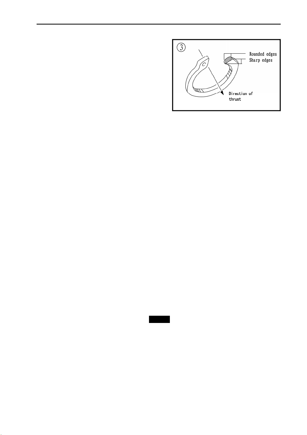
The two basic types of snap rings are machined
and stamped snap rings. Machined snap rings
(Figure 2) can be installed in either direction.
Because both faces have sharp edges. Stamped
snap rings (Figure 3) are manufactured with a
sharp and a round edge. When installing a stamped
snap ring in a thrust application, install the sharp
edge facing away from the part producing the thrust.
E-clips are used when it is not practical to use a
snap ring. Remove E-clips with a flat blade
screwdriver by prying between the shaft and E-clip. To install an E-clip. Center it over the shaft groove
and push or tap it into place
Observe the following when installing snap rings:
GENERALINFORMATION
- 8 -
1. Remove and install snap rings with snap rings pliers. Refer to Basic Tools in this chapter
2. In some applications. it may be necessary to
replace snap rings after removing them
3. Compress or expand snap rings only enough to
install them. If overly expanded. Lose their
retaining ability
4. After installing a snap ring. Make sure it seats
completely
5. Wear eye protection when removing and
installing snap rings
SHOP SIPPLIES
Lubricants and Fluids
Periodic lubrication help ensure a long service life for any type of equipment. Using the correct
type of lubricant is as important as performing the lubrication service. Although in an emergency the
wrong type is better than not using one, The following section describes the types of lubricants most
often required. Make sure to follow the manufacturer’s recommendations for lubricant types
Engine oils
Engine oil for four-stroke the UTV engine use is classified by two standards: the American
Petroleum Institute (API) service classification. The Society of Automotive Engineers (SAE) viscosity
rating Standard classification
The API and SAE information is on all oil container labels. Two letters indicate the API service
classification. The number or sequence of numbers and letter (10W-40SG for example) is the oil’s
viscosity rating. The API service classification and the SAE viscosity index are not indications of oil
quality.
The APL service classification standards, The first letter in the classification S indicates that the oil
is for gasoline engines. The second letter indicates the standard the oil satisfies .
The classifications are: MA (high friction applications) and MB( low frication applications).
NOTE1
Refer to Engine Oil and Filter in
Chapter Three for further information
on API, SAE classifications.
Always use an oil with a classification recommended by the manufacturer, Using an oil with a
different classification can cause engine damage.
Viscosity is an indication of the oil’s thickness. Thin oils have a lower number while thick oil have a
higher number. Engine oils fall into the 5-to50-weight range for single-grade oils.

GENERALINFORMATION
- 9 -
Most manufactures recommend multi-grade oil. These oils perform efficiently across a wide
range of operating conditions. Multi-grade oils are identified by a W after the first number, which
indicates the low-temperature viscosity.
Engine oils are most commonly mineral (petroleum) based, but synthetic and semi-synthetic types
are used more frequently. When selecting engine oil, follow the manufacturer’s recommendation for
type, classification and viscosity.
Greases
Grease is lubricating oil with thickening agents added to it. The National Lubricating Grease
Institute (NLGI) grades grease. Grades range from No.000 to No.6, with No.6 being the thickest.
Typical multipurpose grease is NLGI No.2. For specific applications, manufacturers may recommend
water-resistant type grease or one with an additive such as molybdenum disulfide (MoS2).
Brake fluid
Brake fluid is the hydraulic fluid used to transmit hydraulic pressure (force) to the wheel brakes.
Brake fluid is classified by the Department of Transportation (DOT). Current designations for brake
fluid are DOT 3, DOT 4 and DOT 5, this classification appears on the fluid container.
Each type of brake fluid has its own definite characteristics. Do not intermix different types of brake
fluid as this may cause brake system failure. DOT 5 brake fluid is silicone based. DOT 5 is not
compatible with other brake fluids may cause brake system failure. When adding brake fluid, only use
the fluid recommended by the manufacturer.
Brake fluid will damage any plastic, painted or plated surface it contacts. Use extreme care when
working with brake fluid and remove any spills immediately with soap and water.
Hydraulic brake systems require clean and moisture free brake fluid. Never reuse brake fluid.
Keep containers and reservoirs properly sealed.
WARNING
Never put a mineral-based (Petroleum) oil into the
brake system. Mineral oil causes rubber parts in
the system to causing complete brake failure.
Coolant
Coolant is a mixture of water and antifreeze used to dissipate engine heat. Ethylene glycol is the
most common from of antifreeze. Check the UTV Manufacturer’s recommendations when selecting
antifreeze. Most require one specifically designed for aluminum engines. There types of antifreeze
have additives that inhibit corrosion.
Only mix antifreeze with distilled water. Impurities in tap water may damage internal cooling
system passages.
Cleaners, Degreasers and Solvents
Many chemicals are available to remove oil, grease and other residue from the UTV. Before using
cleaning solvents, consider how they will be used and disposed of , particularly if they are not

GENERALINFORMATION
- 10 -
water-soluble. Local ordinances may types of cleaning chemicals. Refer to Safer in this chapter.
Use brake parts cleaner to brake system components. Brake parts cleaner leaves no residue. Use
electrical contact cleaner is a powerful solvent used to remove fuel deposits and varnish from fuel
system components. Use this cleaner carefully, as it may damage finishes.
Most solvents are designed to be used with a parts washing cabinet for individual component
cleaning. For safety, use only nonflammable or high flash point solvents.
Gasket Sealant
Sealant is used in combination with a gasket or seal. In other applications, such as between
crankcase halves, only a sealant is used. Follow the manufacturer’s recommendation when using a
sealant. Use extreme care when choosing a sealant different sealant based on its resistance to heat,
various fluids and its sealing capabilities.
Gasket Remover
Aerosol gaskets remover can help remove stubborn gasket. This product can speed up the
removal process and prevent damage to the mating surface that may be caused by using a scraping
tool. Most of these types of products are very caustic. Follow the gasket remover manufacturer’s
instructions for use.
Thread locking Compound
A thread locking compound is a fluid applied to the threads of fasteners. After tightening the
fastener, the fluid dries and becomes a solid filler between the threads. This makes it difficult for the
fastener to work loose from vibration or hear expansion and contraction. Some thread locking
compound sparingly. Excess fluid can run into adjoining parts.
CAUTION
Thread locking compounds are anaerobic and will
stress, crack and attack most plastics. Use caution
when using these products in areas where there are
plastic components.
Thread locking compounds are available in a wide range of compounds for various strength,
temperature and repair applications. Follow the manufacturer’s recommendations regarding
compound selection.
Table of contents
Other Hisun Motors Utility Vehicle manuals


Popular Utility Vehicle manuals by other brands


Craftsman
Craftsman ZTS 7500 Operator's manual

Toro
Toro 7359 Operator's manual

Bush Hog
Bush Hog Off Road Utility Vehicle 4430 Operator's manual

Still
Still OCV 01 Original instructions

American Sportworks
American Sportworks 36V series Owner's/operator's manual

Toro
Toro 07252TC Workman 1100 Operator's manual


