Bigaole 3G-A User manual
1.Specification and Furetures
3.LED Status
4、Installation of 3G-A
5.Gain Adjust
Specification
Dimensions: 22mm*31mm
Weight: 7.5g(with cables)
Operating voltage: DC 3.5V-9V
Operating current: 20ma
Maximal angular velocity: 800 degrees/sec
Servo compatibility: 1.52ms analog servo/1.52ms digital servo
Radio compatibility: PPM/PCM/2.4G
Operating Temperature: -15℃--60℃
Features:
2.Function and connection.
Signal Input
AILE IN Signal input for Aileron
ELE Signal input for Elevator
RUD Signal input for Rudder
SW Locking mode switch
Signal Output
AILE OUT Signal output for Aileron
ELEV OUT Signal output for Elevator
RUDD OUT Signal output for Rudder
AILE OUT
ELEV OUT
RUDD OUT
Gyro Gain Adjustment Knob
AIL Gain Adjustment for Aileron ELE Gain Adjustment for Elevator
RUD Gain Adjustment for Rudder
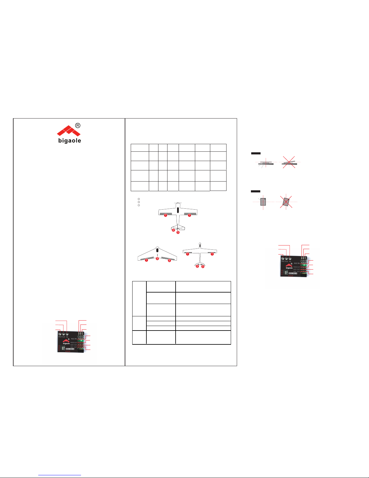
S1/S2/S3 for Corresponding Model
S1 S2 S3 AIL OUT ELEV OUT RUDD OUT
Setting 0 0 0 - - -
Normal
Airplane
Normal Airplane
1 0 0 AIL Servo ELE servo RUD servo
Flying
Wing(delta)
Flying Wing(delta)
0 1 0 Left wing
servo
Right
wing
servo
RUD servo
V-Tail
V-Tail
0 0 1 AIL servo Left wing
servo
Right wing
servo
Blue flashes rapidly
for 3 secs after
powering on
Initialization is normal,please don’t move
the plane
After initialization,
the blue LED will flash
some times
Flash one time for normal model,two times for
flying wing(delta) and three times for
V-Tail
Initializ
ation
Fast circular flashing
of red LED after
initialization
Initialization failed
Blue LED steady on Normal Mode
Red LED steady on AVCS Mode
Working
Status
Both LEDs Extinguished
Gyro Off
Setting
Mode
Entering into Setting
Mode,the Red LED
flashs slowly
Signal of receiver undetected
Transmitter Setting
Thanks for choosing Bigaole 3G-A Unit.3G-A Unit is a small
and light 3-axis gyro with high performance.3G-A supports 3
types of planes,the normal one,flying wing and V-Tail.With
latest MEMS technology ,3G-A unit provides excellent
stability,flexibility and reliability and make the flight follow the
pilots’ operation more exactly through auto-correcting for
aileron,elevator and rudder.With 3G-A unit,a small bird could fly
as better as a big plane.
Easy switch within AVCS mode,Normal mode and Gyro Off mode
Compact,light,could be used in normal airplane,flying wing and
V-tail,with easy switch change.
Excellently optimized for 3D flight without undermining stability.
Easy set-up,separated adjustment of gain for aileron,elevator and
rudder.
Model Selection
4.1 The 3G-A unit must be installed in a flat and stable platform close to
the center of gravity in your plane,the connecting method refers to the
following diagram:(diagram1)
4.2The 3G-A unit must be installed towards forward in a level platform as
showing in diagram2
Turn on the transmitter and create a new model,set the trims and
sub-trims of all channels to zero,making sure that all mix-function are off.
a.trimming potentiometers AIL,ELE and RUD correspond to the gain
adjustment for those three channels,clockwise to increase and
anti-clockwise to reduce.
b.Gyro Compensation Direction Verification
Locking mode switch
Signal input for Rudder
Signal input for Elevator
Signal output for Rudder
Signal input for Aileron
Signal output for Elevator
Signal output for Aileron
Gain Adjustment for Aileron
Gain Adjustment for Elevator
Gain Adjustment for Rudder
Locking mode switch
Signal input for Rudder
Signal input for Elevator
Signal output for Rudder
Signal input for Aileron
Signal output for Elevator
Signal output for Aileron
Gain Adjustment for Aileron
Gain Adjustment for Elevator
Gain Adjustment for Rudder
Double sided
tape Airplane
Side View
The center
Direction of forward flight
of the fuselage
Top View
1
2
3
3G-A Instruction Manual
diagram1
diagram2
◆Connect the gyro,receiver and servo correctly;
◆Choose correct model for your airplane by dialing S1,S2 and S3;
◆Pick up the aircraft around the pitch axis, the roll axis and the yaw axis
to check if the direction of movement of the rudder(control surface) is
correct,otherwise enter into Setting Mode to adjust the compensation
direction of gyro.
◆Move the sticks of aileron,elevator and rudder separately,to see if the
moving direction of rudder(control surface) is correct,otherwise adjust the
normal/reverse of corresponding channel on your transmitter.

6、Switch of AVCS Mode
8.Setting Process
9、First Flight.
10、Troubleshooting
◆Move knobs of AIL,ELE and RUD on the gyro,to adjust the gain of
AIL,ELE and RUD to the middle position,then pick up the aircraft
around the pitch axis, the roll axis and the yaw axis to check if the
reacting amount of rudder(control surface) is appropriate.
Gyro Gain Correction Diagram
SW is the switch to change mode of AVCS for flight.If use 2-section
switch,it just can change between AVCS and Normal mode.For
3-section switch,apart from the AVCS and Normal mode,it has an
additional Gyro Off Mode,refer to the following table:
Flight Mode Range of
switch
Signal Pulse
Width LED Status
NonLocking Less 1320US Blue on
Gyro Off Middle 1520+/-200US Off
Locking
(AVCS)More 1720 Red on
7.Stick Centering Calibration
First,to get the best performance,centering function is
required.Make the stick in your transmitter to be centered and
then enter into Setting Mode to calibrate.When you use the
3G-A unit for the first time,or change your transmitter,the
calibration of stick center is required,after centering,all servos
will be centered automatically.The center of aileron,elevator
and rudder could be obtained by adjusting the linkage rods.The
function of sub-trim in your transmitter could not be used.
1 Turn on transmitter,set
the trims of channel
ELE,AIL and RUD to
zero,dial S1,S2 and S3
downwardly(OFF),
then,connect the 3G-A
with power supply.
2.Stick Center
calibration
a、Red and Blue LED
will flash one time
simultaneously: enter
into center calibration
b、Waiting for 1
second.
c、Blue LED flashes
rapidly for 1
second,calibration is in
process
d、One second
later,blue LED will give
a rapid flash,calibration
finished with success.
3、Quit Setting Mode
Stick center calibration
finished or the setting of
Nor/Rev for gyro
finished,,unplug the
power supply and quit
setting mode.
Waiting for 5 seconds
4、Nor/Rev Setting of Gyro.
a.)Red and Blue LED will flash 2 times
simultaneously: enter into Normal and Reverse
Setting for Gyro
b.)Waiting for 1 second and the LED status will
enter into circulatory flash,the color of LED
represent the direction of gyro
compensation,blue for Normal and Red for
reverse.
c.) Blue or RED LED will falsh 1time per second
for 5 times in total.,now you can move the
rudder stick to adjust the compensation
direction of aileron.
d) Blue or Red LED will flash 2times per
second for 5 times in total,now you can
move the rudder stick to adjust the
compensation direction of elevator .
e)Blue LED(or Red)will flash 3 times per
second for 5 times in total,then move the
rudder stick to set the compensation
direction of rudder.
5Direction of Gyro Calibration
a)During the process of flash,move the
rudder stick to left or right to switch the
direction of gyro calibration
Nor(Blue flash)Rev(Red Flash),or
Rev(Red Flash) Nor(Blue Flash)
b)When moving the rudder stick,LED keeps
rapid flashing until it returns to the center.
For the first flight,please check if the direction of gyro
compensation,direction of control by stick are correct,and set the
gain to a small volume,and after times of flight test,then set it to
a appropriate volume,in order to get the most excellent flight
performance.
◆Airplane swings regular,rapid and alternately
Decrease the gyro gain.
◆Airplane swings irregularly。
Check if the vibration of engine with airframe is too much,reduce
the vibration ,use soft double-sided foam adhesive to install the
gyro.。
◆Airplane rotates irregularly,side tumbling or overturning after
taking off.
Chek if the direction of movement of AIL,ELE and RUD are
correct. Move sticks of Aileron,Elevator and Rudder separately to
check if the direction of movement of rudder(control surface) are
correct.
◆Rotate on a direction slowly and continually.
Check if the installation of rudder(control surface) stick is
level,adjust the center of servo.
1 2 3
45 6
1.Rotating the plane around pitch axis,check the correction of gain
for elevator as showing in the diagram 1 and 2.
2.Rotating the plane around the roll axis,check the correction of gain
for aileron as showing in the diagram 3 and 4.
3.Rotating the plane around the yaw axis,check the correction of gain
for rudder as showing in the diagram 5 and 6.
ATTENTION:
1.Checking that the mixing of flying wing or v-tail has been
disabled within your transmitter as 3G-A has already had these
functions in.
2.3G-A has to re-learn the center position after making a trim
or subtrim change within the transmitter,or the servos may move
to the full left or full right when switching to AVCS mode.To do
this,please quickly flip the flight mode switch two or three times
between Normal mode and AVCS mode per second.


