BIGGER BOYZ TOYZ AUSTRALIA PTY.LTD BBT-GEN-3.5KWINV User manual

OWNER’S MANUAL
Assembly & Operating Instructions
BBT 3.5KW Electric Start
Sine Wave Inverter Generator
MODEL NO. BBT-GEN-3.5KWINV

2
WWW.BBTA.COM.AU BBT-GEN-3.5KWINV
To the Owner
Thank you for purchasing our Generator. It was carefully engineered to provide excellent performance when
properly operated and maintained.
Please read this entire manual prior to operating the Generator. It instructs you how to safely and easily set
up, operate and maintain your Generator. Please be sure that you and any other persons who will operate
the Generator carefully follow the recommended safety practices at all times. Failure to do so could result in
personal injury or property damage.
All information in this manual is relative to the most recent product information available at the time of printing.
Review this manual frequently to familiarise yourself with the machine, its features and operation. Please be
aware that this Owner’s Manual may cover a range of product specifications for various models. Characteristics
and features discussed and/or illustrated in this manual may not be applicable to all models. We reserve the right
to change product specifications, designs and equipment without notice and without incurring obligation.
All the power testing information used to establish the power rating of the engine equipped on this Generator
can be found in the engine manufacturer’s manual or website. If you have any problems or questions concerning
the machine, please contact our Customer Support Department.
Throughout this manual, all references to right and left side of the Generator are observed from the operating
position. The engine manufacturer is responsible for all engine-related issues with regards to performance,
power-rating, specifications, warranty and service. Please refer to the engine manufacturer’s Owner’s Manual
packed separately with your Generator for more information.
Customer Support
Please do NOT return the Generator without first contacting the Customer Support Department at
bbt@bbta.com.au.
If you have difficulty assembling this product or have any questions regarding the controls, operation, or
maintenance of this Generator, please contact our Customer Support Department.
SAVE THESE INSTRUCTIONS

3
WWW.BBTA.COM.AUBBT-GEN-3.5KWINV
TABLE OF CONTENTS
Page(s)
To the Owner .........................................................................................................................................................2
Customer Support..................................................................................................................................................2
TABLE OF CONTENTS .............................................................................................................................3
IMPORTANT SAFETY INFORMATION ................................................................................................. 4-5
Additional Information and Potential Changes...................................................................................................4
Safety Information.................................................................................................................................................5
PARTS LOCATION................................................................................................................................ 6-7
CONTROL FUNCTION..............................................................................................................................8
BEFORE OPERATION...............................................................................................................................9
Pre-operation Check ..............................................................................................................................................9
OPERATION..................................................................................................................................... 10-12
Starting the Engine..............................................................................................................................................10
Using Electric Power ............................................................................................................................................11
Stopping the Engine............................................................................................................................................12
MAINTENANCE............................................................................................................................... 13-15
Engine Oil Replacement ......................................................................................................................................14
Air Filter................................................................................................................................................................14
Cleaning and Adjusting Spark Plug ....................................................................................................................14
Fuel Tank Filter.....................................................................................................................................................15
Muffler Screen .....................................................................................................................................................15
TROUBLESHOOTING.............................................................................................................................16
Engine won’t start ...............................................................................................................................................16
Generator won’t produce power........................................................................................................................16
STORAGE ..............................................................................................................................................16
SPECIFICATIONS....................................................................................................................................17
WIRING DIAGRAM.......................................................................................................................... 18-19
EXPLODED DIAGRAM & PARTS LIST.............................................................................................. 20-27
FIG A: Crankcase Assembly..................................................................................................................................20
FIG B: Cylinder Head 1 .........................................................................................................................................20
FIG C: Crankshaft Piston 2 ...................................................................................................................................21
FIG D: Camshaft 3 ................................................................................................................................................21
FIG E. Oil Pump 4 .................................................................................................................................................21
FIG F: Air Cleaner 5 ..............................................................................................................................................22
FIG G: Carburettor 6 ............................................................................................................................................22
FIG H: Recoil Starter 7..........................................................................................................................................22
FIG I: Muffler 8 .....................................................................................................................................................23
FIG J: Generator 9 ................................................................................................................................................23
FIG K. Starter 10 ...................................................................................................................................................23
FIG L. Fuel Tank 11 ...............................................................................................................................................24
FIG M: Shell 12 .....................................................................................................................................................24
FIG N. Governor 14 .............................................................................................................................................26
FIG O: Inverter 15.................................................................................................................................................26
FIG P: Electric Starter.16.......................................................................................................................................26
FIG Q. Control Panel 17 (FOR EU) .......................................................................................................................27
WARRANTY & SERVICE ........................................................................................................................27
YOU MAY ALSO LIKE ...........................................................................................................................28
4
WWW.BBTA.COM.AU BBT-GEN-3.5KWINV
IMPORTANT SAFETY INFORMATION
Additional Information and Potential Changes
We reserve the right to discontinue, change, and improve our products at any time without notice or obligation
to the purchaser. The descriptions and sections contained in this manual were in effect at the time of printing.
Equipment described within this manual may be optional. Some illustrations may not be applicable to your
machine.
WARNING: Read and thoroughly understand all instructions in this manual and on the safety decals
before assembling or operating this Generator. Failure to do so may cause serious injury or death.
Do not allow anyone to operate this Generator who has not read this manual. As with all power
equipment, a Generator can be dangerous if assembled or used improperly. Do not operate this
Generator if you have any questions concerning its safe operation. To get answers to any questions,
call our Customer Support Department.
This SAFETY ALERT SYMBOL identifies important safety messages in this manual. Failure to follow
this important safety information may result in serious injury or death.
DANGER! This Generator was built to be operated according to the safe operation practices in this
manual. As with any type of power equipment, carelessness or error on the part of the operator can
result in serious injury. Failure to observe the following safety instructions could result in serious injury
or death.
The following signals, words and meanings are intended to explain the levels of risk associated with this product.
DANGER indicates a hazardous situation which, if not avoided, will result in serious injury or
death.
WARNING indicates a hazardous situation which, if not avoided, could result in serious injury
or death.
CAUTION indicates a hazardous situation which, if not avoided, could result in minor or
moderate injury.
NOTICE is important information about the proper use of your Generator. Failure to follow
this instruction could result in damage to your Generator or property.
WARNING! Your Responsibility—Restrict the use of this power machine to persons who have read,
understood and will follow the warnings and instructions in this manual and on the machine.
SAVE THESE INSTRUCTIONS!
5
WWW.BBTA.COM.AUBBT-GEN-3.5KWINV
PLEASE READ AND UNDERSTAND THIS MANUAL COMPLETELY
BEFORE OPERATING THE MACHINE.
Safety Information
Exhaust Fumes are Poisonous
• NEVER operate the engine in a closed area or it may cause unconsciousness and death within a short time.
Operate the engine in a well ventilated area.
Fuel is Highly Flammable and Poisonous
• Always turn off the engine when refuelling
• NEVER refuel while smoking or in the vicinity of an open flame.
• Take care not to spill any fuel on the engine or muffler when refuelling.
• If you swallow any fuel, inhale fuel vapour, or allow any to get in your eyes, see your doctor immediately.
If any fuel spills on your skin or clothing, immediately wash with soap and water and change your clothes.
• When operating or transporting the machine, be sure it is kept upright. If it tilts, fuel may leak from the
carburettor or fuel tank.
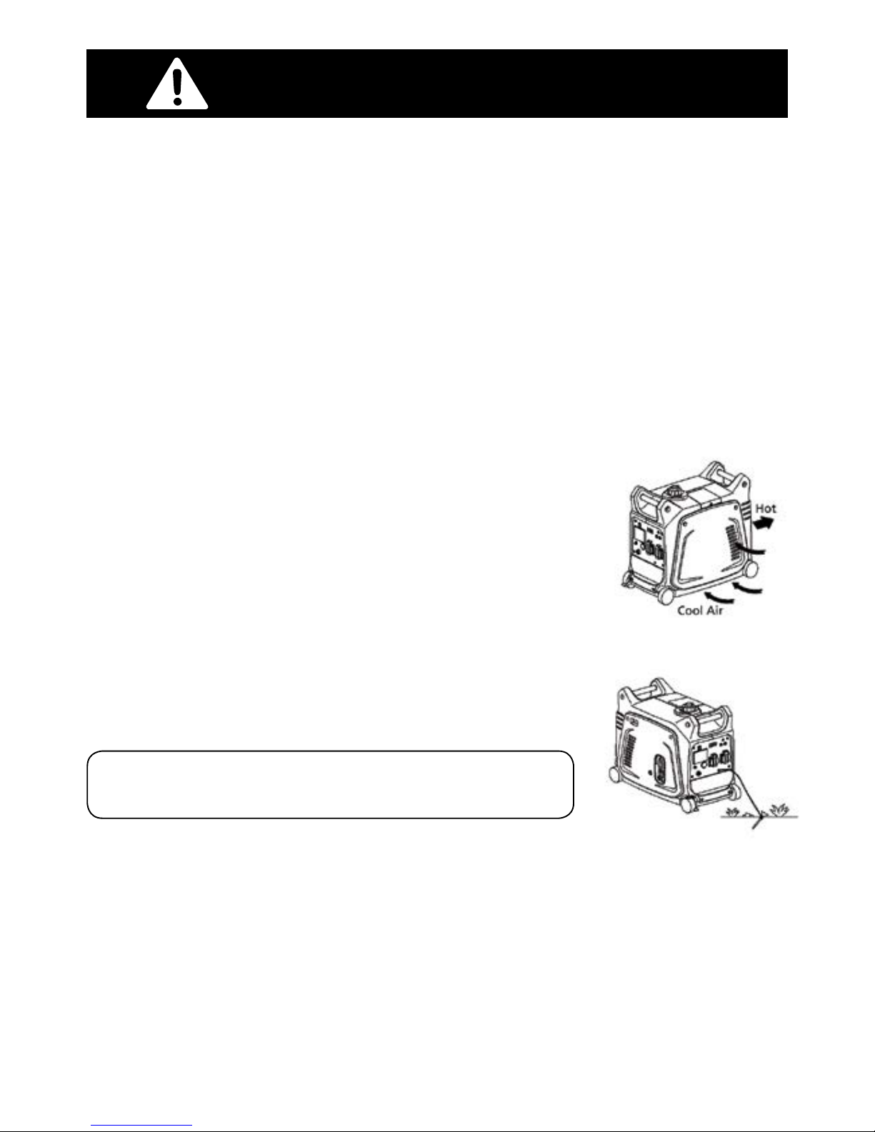
Engine and Muffler may be Hot
• Place the machine in a place where pedestrians or children are not likely to
touch the machine.
• Avoid placing any flammable materials near the exhaust outlet during operation.
• Keep the machine at least 1 m ( 3 ft ) from buildings or other equipment, or the
engine may overheat.
• Avoid operating the engine with a dust cover.
• Be sure to carry the generator only by its carrying handle.
• Put the machine on the flat ground, for the machine to eliminate heat freely.
Electric Shock Prevention
• NEVER operate the engine in rain or snow.
• NEVER touch the machine with wet hands or electrical shock will occur.
• Be sure to ground (earth) the generator.
Connection Notes
• Avoid connecting the generator to commercial power outlet.
• Avoid connecting the generator in parallel with any other generator.
IMPORTANT SAFETY INFORMATION
Note: Use ground (earth) lead of sufficient current capacity.
Diameter: 0.12mm (0.005 in)/ampere, EX: 10 Ampere – 1.2mm (0.055 in)
Table of contents
Popular Inverter manuals by other brands


BARRON
BARRON EXITRONIX Tucson Micro Series installation instructions

Baumer
Baumer HUBNER TDP 0,2 Series Mounting and operating instructions

electroil
electroil ITTPD11W-RS-BC Operation and Maintenance Handbook

Silicon Solar
Silicon Solar TPS555-1230 instruction manual

Mission Critical
Mission Critical Xantrex Freedom SW-RVC owner's guide

HP
HP 3312A Operating and service manual


