Bigham Brothers 888 Use and care manual

Operator’s & Repair Parts Manual
For Models:
Do Not Use or Operate This Equipment
Until You Have Read and Understood This Manual
The purpose of this manual is to explain maintenance requirements and adjustments which are
necessary for the most efcient operation of the machine. Read this manual thoroughly and com-
pletely before using your machine. Keep this manual handy for reference when questions arise.
Should you have questions or difculties which your dealer or representative are unable to
answer, please call or write:
Bigham Brothers, Inc. 705 E. Slaton Rd. P.O. Box 3338 Lubbock, TX 79452
Telephone: (806) 745-0384 Fax: (806) 745-1082
SAFETY FIRST
PREVENT ACCIDENTS BY “THINKING SAFETY”
IN UNLOADING, SETTING UP, MOVING, STORAGE
AND OPERATING ALL EQUIPMENT.
© 2012 Bigham Brothers, Inc. This document may not be reproduced in whole or in part without prior written permission of Bigham Brothers, Inc.
P/N B12-18C Revised 12-19-2012. Printed in the U.S.A. Specications and design subject to change without notice.
$7.
00
U.S.
760-802
760-807
760-808
Gang Bundle Assembly Model 888 Cultivator 4x7”
Gang Bundle Assembly Model 888 Cultivator 7x7”
Gang Bundle Assembly Model 888 Cultivator 7x7”
(Wrap Around)
Model 888
Cultivator/Lister

Form # B11-1ST
(806) 745-0384 705 E. Slaton Rd. P.O. Box 3338 Lubbock, TX 79452
BIGHAM BROTHERS, INC.
A MESSAGE TO THE OWNER AND OPERATOR:
This machine was carefully designed and manufactured to give you dependable service. To keep it running
efciently, read the instructions in this Operator’s Manual. Check each item and acquaint yourself with the
adjustments required to obtain efcient operation and maximum performance. Remember, the machines
performance depends on how you operate and care for it.
After the operating season, thoroughly clean your machine and inspect it. Preventive maintenance saves time
and pays dividends. Your dealer has original equipment parts which assure proper t and best performance.
Record the model number, serial number and date of purchase in the space provided on this page. Your dealer
needs this information to give you efcient service when you order parts or attachments. The model number
and serial number appear on the identication plate on the front left side of the tool bar mast.
The Warranty on your machine is included with this manual. Your dealer will review both this manual and the
warranty with you when you take delivery of your machine.
WARRANTY
Bigham Brothers, Inc. warrants all products of its manufacture to be free from defects in materials and
workmanship for a period of six months from date of delivery to the retail purchaser. Parts assumed to
be defective must be returned F.O.B. Lubbock, Texas for our inspection or inspected in the eld by our
authorized representative. Our obligation under this warranty is limited to replacement or repair of the
defective part and does not cover other damages to persons or property. Other than the aforesaid, no
warranties of merchantability or tness for a particular purpose will apply. We do not assume liability for
altered or remanufactured components or machines or applications beyond their intended use. Some states
do not allow limitation of how long an implied warranty lasts, or exclusions of, or limitations on relief such
as incidental or consequential damages, so the above limitations or exclusion may not apply to you. This
warranty gives you specic legal rights and you may have other rights which vary from state to state.
Warranty does not cover damage due to abuse, neglect, collision, towing, pulling, normal wear and tear or
any other factor beyond the control of the manufacturer. Tool bars that are bent, bowed or that have been
welded on or modied in any way are specically excluded from any warranties.
LIMITED LIFETIME WARRANTY ON
TOOL BAR CLAMPS
Bigham Brothers, Inc. will replace any ductile iron clamp body that breaks or cracks under normal use for
as long as the original purchaser owns them. This includes all replaceable bolt ductile iron clamps sold by
Bigham Brothers, Inc. after December 31, 1987.
Clamps that fail should be returned to Bigham Brothers, Inc. freight prepaid along with caps, bolts, set screws
and nuts for evaluation. If found to have failed under normal operating conditions, a new clamp body will be
returned along with your old caps, bolts, set screws and nuts. Only clamps that have been used with Grade 2
bolts of the proper size will be replaced. All other provisions of the above warranty apply.

(806) 745-0384 705 E. Slaton Rd. P.O. Box 3338 Lubbock, TX 79452
Page 1
Form # B12-18C
BIGHAM BROTHERS, INC.
Contents
Page ...........................Description
Inside Front Cover .....Warranty
1...............................Table of Contents
2...............................Safety Precautions
3...............................Introduction
4...............................Description
5...............................Mount Gangs to Tool Bar
6...............................Set Operating Depth: Front Tire or Coulter
7...............................Center Mounted Swivel Coulter
8...............................Tooling Bar Options
9...............................Rear Shanks
10...............................Mount Spring Loaded Chisel Clamp
11...............................Mount Barring-Off Disc Hubs
12...............................Attaching Cultivator to Tractor
Parts Breakdowns
13...............................Gang and Parallel Linkage (Wrap and Split Mount)
14...............................Gang and Parallel Linkage (Rear Mount)
15...............................Adjustable Swivel Coulter-Model Years 2012-Current
16...............................Gang and Parallel Linkage To 2012 (Wrap and Split Mount)
17...............................Gang and Parallel Linkage To 2012 (Rear Mount)
18...............................Adjustable Swivel Coulter-Model Years 2011-Current
19...............................Adjustable Swivel Coulter-Model Years 2010-2011
20...............................Swivel Coulter-Model Years 2011-Current
21...............................Swivel Coulter-Model Years 2010-2011
22...............................Rigid Coulter-Model Years 2011-Current
23...............................Rigid Coulter-Model Years 2010-2011
24...............................Wheel and Tire Bundle
25...............................Wheel and Tire Bundle To 2012
26...............................Barring-off Disc Bundle, Quick Adjust
27...............................Barring-off Disc Bundle, 4” Tooling Tube
28...............................Rigid Chisel Shank
29...............................Spring Reset Chisel Clamp
30...............................Bedding and Cultivation Tools
31...............................Crop Hood Assembly
32...............................Crop Shield Assembly
Page 2
Form # B12-18C
(806) 745-0384 705 E. Slaton Rd. P.O. Box 3338 Lubbock, TX 79452
BIGHAM BROTHERS, INC.
Safety Precautions:
Be alert when you see this symbol in the instructions.
It warns of a hazard which might lead to injury.
It means: “Attention! Become alert! Your Safety Is Involved!”
Before Use: DO NOT operate this equipment until you
have read and understood this manual.
* Assure operators have read and are familiar with the instructions contained in the Operator’s Manual
* If working on the Model 888 Cultivator, make sure it is level and stable. Proper stands should be lowered and
secured. Use support blocks when necessary. The work area should be on a level, load bearing surface, e.g.
concrete oor. NEVER, NEVER work under a Cultivator while it is supported by only the tractor’s hydraulics.
* Consult the “Tractor Manufacturers Manual” for instructions on safe mounting of implements and operating
methods.
* Never stand between the Cultivator and tractor with engine running.
During Use:
* Check and tighten all bolts after 30 minutes of initial operation and after adjustments have been made.
* Assure the Model 888 Cultivator is correctly attached to the tractor.
* Be alert to underground obstructions, e.g. large stones, tree roots, cables, pipe lines, etc. Should an obstruction
be encountered, STOP IMMEDIATELY AND INVESTIGATE.
NOTIFY THE APPROPRIATE AUTHORITY IF BURIED CABLES OR PIPELINES ARE
SUSPECTED. Non-hazardous obstructions should be removed before continuing operation.
* Keep operating speeds at a safe level.
* Never allow anyone to ride on the Model 888 Cultivator during operation.
* Never travel in reverse with the Model 888 Cultivator in the operating position.
* Never carry out adjustments or repairs to a mounted Model 888 Cultivator unless the tractor engine is stopped
and the Model 888 Cultivator is rmly supported or lowered to the ground.
* Inspect the Model 888 Cultivator for wear or damage on a regular basis.
* Check all nuts, bolts and other fasteners for tightness on a regular basis. Replace worn fasteners as needed.
* Carry out maintenance and lubrication procedures as detailed in this manual.
* When disconnecting the Model 888 Cultivator do so on a level, hard surface. Assure it is left in a stable position
with proper stands in the correct position.
Always:
* Wear gloves and safety footwear when handling worn parts with sharp edges.
* Assure the Model 888 Cultivator is not operated by untrained persons.
* Use the Model 888 Cultivator only for the purpose for which it was designed and tested, and always according
to the instructions contained in this manual.
* Reduce speed when transporting over uneven or rough terrain.
* Place a “Slow Moving Vehicle” emblem on the rear of the unit before driving on open roads.
* Keep hands, feet and clothing away from all moving parts.
* Exercise care when adjusting gangs, disc coulters or other tooling. The assemblies are heavy and may have
sharp edges.
“Left” and “Right” of the machine refers to the side when standing behind the Cultivator and facing the tractor.

(806) 745-0384 705 E. Slaton Rd. P.O. Box 3338 Lubbock, TX 79452
Page 3
Form # B12-18C
BIGHAM BROTHERS, INC.
BE A SAFE OPERATOR, THINK BEFORE OPERATING.
READ ALL INSTRUCTIONS BEFORE
ASSEMBLY OR OPERATION OF THE CULTIVATOR!
INTRODUCTION:
The Model 888 Cultivator/Lister has two primary functions: cultivation of growing crops and pre-plant bedding
operations. Independent parallel-linked gangs assure consistent operation over uneven ground.
When congured as a cultivator, a combination of sweeps and barring-off discs clear weeds from areas between
rows of growing plants.
For bedding operations, busters, lister bottoms, or bedding sweeps are mounted on the shank at the rear of each
gang.
In irrigation trench operation, a small buster, shovel, or point replaces the buster or bedding sweep used in bedding
operations.
Model 888 Cultivator on Rigid Tool Bar

Page 4
Form # B12-18C
(806) 745-0384 705 E. Slaton Rd. P.O. Box 3338 Lubbock, TX 79452
BIGHAM BROTHERS, INC.
The BIGHAM BROTHERS Model 888 Cultivator is
equipped with an uneven number of parallel linkage
tooling gangs—one for each crop seedbed plus one.
Normal conguration includes a leading trash-cutting
coulter with depth band or height adjustable tire, a center
swivel coulter, sweeps or barring-off discs, and a rear
chisel shank with bedding or cultivating tools.
Gang Placement
Check/set row spacing from the center line at the point
of the sweep, buster, or irrigation shovel—not at the top
of the clamp on the tool bar. Manufacturing tolerances
may affect position at the end of the tool. Set center gang
between two stringer plates. Ensure center of sweep or
buster is on center. Run a tape from center point and
ensure each point is the right distance from this point.
For example, for 38” rows, points should be at 38”, 76”,
114”, 152”, 190”, 228”, etc. from the center point. Do not
measure one point to the next, because any error can be
compounded to the next gang.
Set chisel shanks all the way to the top by adjusting the
4x4 mounting tube to its upper-most position.
(806) 745-0384 705 E. Slaton Rd. P.O. Box 3338 Lubbock, TX 79452
Page 5
Form # B12-18C
BIGHAM BROTHERS, INC.
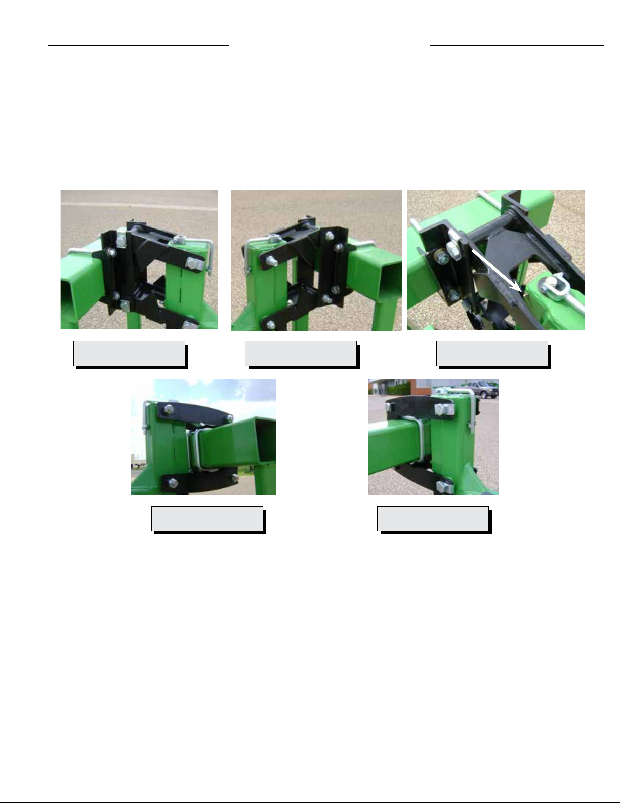
Mount Gangs to Tool Bar
Two types of gang mounting assemblies are available: the Rear Mount assembly and the Wrap-around assembly.
Each is fastened by use of two u-bolts for each gang. See pictures 1-5. Position each clamp so the gang is centered
between the crop rows. Note alignment cuff on rear mounted clamp assembly. If equipped with screw jack, ll the
jack cavity with grease once each season through the grease zerk in picture three.
Picture 1 Picture 2 Picture 3
Picture 4 Picture 5

Page 6
Form # B12-18C
(806) 745-0384 705 E. Slaton Rd. P.O. Box 3338 Lubbock, TX 79452
BIGHAM BROTHERS, INC.
Set Operating Depth: Front Tire or Coulter
Gang operating height is set by either an adjustable depth control tire or one of several front-mounted residue
cutting coulters. Rigid and Swivel Coulters mount directly to the gang and do not adjust vertically. The Adjustable
Coulter and Adjustable Tire allow vertical adjustment via the screw jack (picture 8).
Using the adjustable coulter or tire allows working height of the gang independently of the other tooling.
Note: Adjust gauge wheels or three-point lift so the parallel linkages on the gang are level at operating depth.
If hard ground prevents the tool from fully engaging, install down-pressure spring kit. Failure to give the gang
proper up and down travel range can result in damage to coulters, wheels, tooling, and gang.
On a gang with rigid coulter or xed swivel coulter, all tooling heights are set to the coulter.
Scrapers are available to keep wet soil from sticking to coulters (picture 10).
See pictures 6-10.
Picture 6 Picture 7 Picture 8
Picture 9 Picture 10
(806) 745-0384 705 E. Slaton Rd. P.O. Box 3338 Lubbock, TX 79452
Page 7
Form # B12-18C
BIGHAM BROTHERS, INC.
Center Mounted Swivel Coulter
Non-adjustable swivel coulter mounts to the frame behind an adjustable tire. Does not include depth band.
See pictures 11-12.
Picture 11 Picture 12

Page 8
Form # B12-18C
(806) 745-0384 705 E. Slaton Rd. P.O. Box 3338 Lubbock, TX 79452
BIGHAM BROTHERS, INC.
Tooling Bar Options
Two tooling bars are available for mounting tools like barring off discs or cultivator sweeps.
The Quick-Adjust tooling tube positions barring off discs with pin settings. No wrenches necessary for side-to-side
or vertical disc adjustments.
The 4x4 tooling tube mounts standard shanks and clamps for discs or cultivator sweeps.
Each tube is held in place with a set screw on top of the gang tube (picture 13).
See pictures 13-14.
Picture 13 Picture 14

(806) 745-0384 705 E. Slaton Rd. P.O. Box 3338 Lubbock, TX 79452
Page 9
Form # B12-18C
BIGHAM BROTHERS, INC.
Rear Shanks
The cultivator gang mounts a chisel shank featuring Bigham Brothers’ No-Twist™ foot piece. Note the rear mounting
tube that may be adjusted vertically with four ange bolts. Start by moving the
The rigid shank mounts directly to the chisel shank mount tube at the rear of the gang. If you are mounting a 1x3”
straight shank with a clamp, request the mounting tube, part number 689-244 without the chisel shank guides.
The Spring Reset Chisel Clamp attaches a chisel shank to the rear tooling tube through an automatic spring reset
mechanism. Note the three spring mounting positions that give pressure settings of 400, 800, and 1200 pounds. See
special mounting instructions on next page.
See pictures 15-18.
Picture 15 Picture 16 Picture 17

Page 10
Form # B12-18C
(806) 745-0384 705 E. Slaton Rd. P.O. Box 3338 Lubbock, TX 79452
BIGHAM BROTHERS, INC.
The Spring Loaded Chisel Clamp should be assembled when you receive it. How-
ever, you will need to partially disassemble it to mount it on the 4x4 tooling bar.
When assembled, the chisel shank clevis obscures the bottom end of the u-bolt
(#1) which secures the clamp to the 4x4” bar. To install the nut, you must rst
remove the pivot bolt (# 2). The nut will be left loose from the factory. You may
need a hammer and punch to drive the bolt out and align the clevis when you are
ready to reinsert the bolt.
When the bolt is removed, swing the clevis back out of the way (# 3). Make sure the bushing does not fall out. Insert the
u-bolt, and securely fasten the clamp to the 4x4” bar (# 4). Realign the clevis. Use a tapered punch or other tool to align.
DO NOT ALIGN THE CLEVIS WITH YOUR FINGER. Reinsert bolt and lock washer, then tighten to 150 foot-
pounds.
Grease the clevis at the grease zerk (# 1) and periodically thereafter.
Note that point pressure (trip pressure) is set by positioning the spring assembly in the proper holes in the clevis. The
front holes (# 6) set the pressure at 400 pounds. The center holes (# 7) set pressure at 800 pounds. The rear holes (# 8) set
it at 1200 pounds.
The spring pressure is set at the factory with adjusting nuts on top and bottom. The distance between the inside of the top
bracket (# 9) and the bottom cap (# 10) should be set at 17-1/4 inches plus or minus 1/8 inch. The spring pressure is set
at the factory and SHOULD NOT BE ADJUSTED IN THE FIELD. Adjusting spring pressure will result in changing
operating angles and tool alignment.
1
3
2
4
5
6
7
8
17 1/4”
+- 1/8”
9
10
Picture 18 Picture 19 Picture 20
Picture 21 Picture 22
Picture 23

(806) 745-0384 705 E. Slaton Rd. P.O. Box 3338 Lubbock, TX 79452
Page 11
Form # B12-18C
BIGHAM BROTHERS, INC.
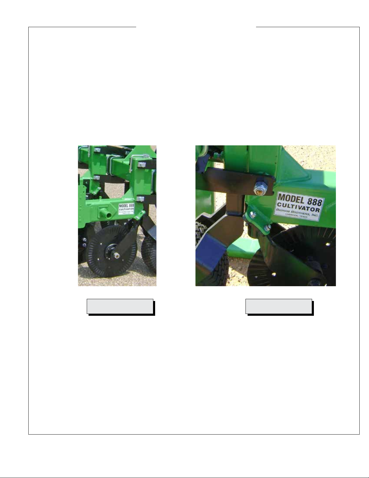
Warning! Position barring-off disc hubs as detailed below.
Barring-Off Disc Hubs Mounted on Cultivator Gangs
Description:
(1.) Covering Disc Hubs MUST run in the correct direction or the spindle bolt will work loose, resulting in loss of
disc and bearings. The spindle is fastened with either a left-handed or right-handed bolt. It MUST be installed on the
proper side of the row to insure that the bolt stays tight during operation.
(2.) Spindles are different on left- and right-handed hubs (left-handed bolt/right handed bolt).
(3.) Spindles are made to run with EITHER a Link Belt/BBI Premium bearing OR a Fafnir (a few older models)
bearing. They will not interchange.
Right-hand hub on LEFT side Right hand bolt with red marking Left hand spindle detail
Identication of Left-Hand and Right-Hand hubs
Hubs are made left- or right-handed by the Spindle Bolt. Upper right shows marking on the hex spindle shaft. There
are three markings:
(A.) F/L: The spindle marked ‘F’ takes the Fafnir bearing only. The ‘L’ spindle will use either Link Belt or BBI
Premium bearings. Order bearings accordingly.
(B.) LH/RH Marks spindle as either Left-Hand or Right Hand. This refers to the direction the spindle bolt tightens.
A left-hand spindle uses a left-hand thread spindle bolt. A right-hand spindle uses a right-hand thread spindle bolt.
The right hand bolt may be marked with RED paint.
(C.) Soil Flow Direction - The arrow points to the REAR of the machine.
Cultivator Field Installation Instructions:
Locate the barring-off disc assemblies as shown in the photo at left. Note that the
hub with the right-hand bolt is placed on the left side of the gang as seen from the
rear. The right-hand bolt points right and the left-hand bolt points left as seen from
the rear of the plow.
Note: If you reverse the direction of soil ow (ex. move soil toward row instead of
away from row), move disc to the opposite side of the gang so the hub is facing the
same direction in relation to the plow.
Rear of Machine
Rear of Machine
Picture 20 Picture 21 Picture 22
Picture 23
Hub with Right
Hand Bolt
Hub with Left
Hand Bolt
Front of Machine
Page 12
Form # B12-18C
(806) 745-0384 705 E. Slaton Rd. P.O. Box 3338 Lubbock, TX 79452
BIGHAM BROTHERS, INC.
Attaching Tractor to
Model 888 Cultivator
Choosing the proper tractor:
1. It is extremely important to utilize a tractor with
sufcient horsepower and traction. Soil conditions and
tooling (i.e. bedding tools vs. cultivator sweeps) will
effect horsepower requirements, but allow 10-30 HP per
row, i.e., 4 rows requires a 40-120 HP tractor.
2. The Model 888 Cultivator is equipped with rear-
extending gangs. The three-point linkage of the tractor
must allow 36 inches between the ground and the lower
hitch points in the “fully raised” position to provide
adequate transport clearance.
3. Ensure that both the right and left lift arms are
identical in length, and the tool bar is level (right to left).
They must be equal to achieve uniform operating depth
and transport clearance.
4. Sway blocks or stabilizing chains should be adjusted
to minimize lateral movement.
5. Insure tractor has sufcient front end weight to permit
constant positive steering at all times.
6. Insure tire pressures are equal and set at
manufacturer’s recommended pressures.
CAUTION
NEVER STAND BETWEEN TRACTOR
AND MODEL 888 CULTIVATOR WITH THE
TRACTOR ENGINE RUNNING.
A. Tractors Equipped With Quick Hitches:
1. Attach quick hitch to the Model 888 Cultivator and make
sure lower pin locks are secured.
2. Raise the parking stand into the clamp body or remove to
allow the Model 888 Cultivator into a working position.
3. When disconnecting the Model 888 Cultivator adjust stands
to leave the Tool Bar tilted slightly forward. This will permit
easier disconnecting and reattaching.
WARNING: Never Work under the Model
888 Cultivator When it is in the raised position.
Always lower the unit to the ground before
making any adjustments.
Tractors Without Quick Hitch:
1. Attach lower lift arms of the tractor to the Model 888
Cultivator utilizing appropriate pins. Standard equipment for
all units is a Category III wide hitch with 1-7/16” Lower and
1-1/4” Upper Pin diameters.
2. Attach top link after connecting lower lift arms. Raise
parking stands into clamps or remove. When disconnecting,
place stand to leave the Model 888 Cultivator in a stable
position.
CAUTION
DO NOT MOVE TRACTOR WITHOUT
MAKING SURE TOP HITCH IS
CONNECTED TO TRACTOR.
Field Use and Adjustments
NEVER ALLOW ANYONE TO
RIDE ON THIS EQUIPMENT
DURING OPERATION
1. Maximum operating speed 4 - 8 mph. If obstructions
are present, lower operating speed to a safe level. This
will help minimize damage.
2. Adjust the depth by raising or lowering the depth
control wheels.
3. The frame must be horizontal (level) front to back
when in use. Adjust by lengthening or shortening the
tractor’s top link.
4. Check and adjust if necessary the coulter position in
relation to the tillage shank working depth.
5. Never reverse the tractor when the Model 888
Cultivator is in the ground.
6. Do not make sharp turns when the Model 888
Cultivator is in the ground.
7. For best results make sure to operate on matching
rows.
(806) 745-0384 705 E. Slaton Rd. P.O. Box 3338 Lubbock, TX 79452
Page 13
Form # B12-18C
BIGHAM BROTHERS, INC.
Qty. Req. Per Assy.
Ref# P/N Description (* As Required)
Qty. Req. Per Assy.
Ref# P/N Description (* As Required)
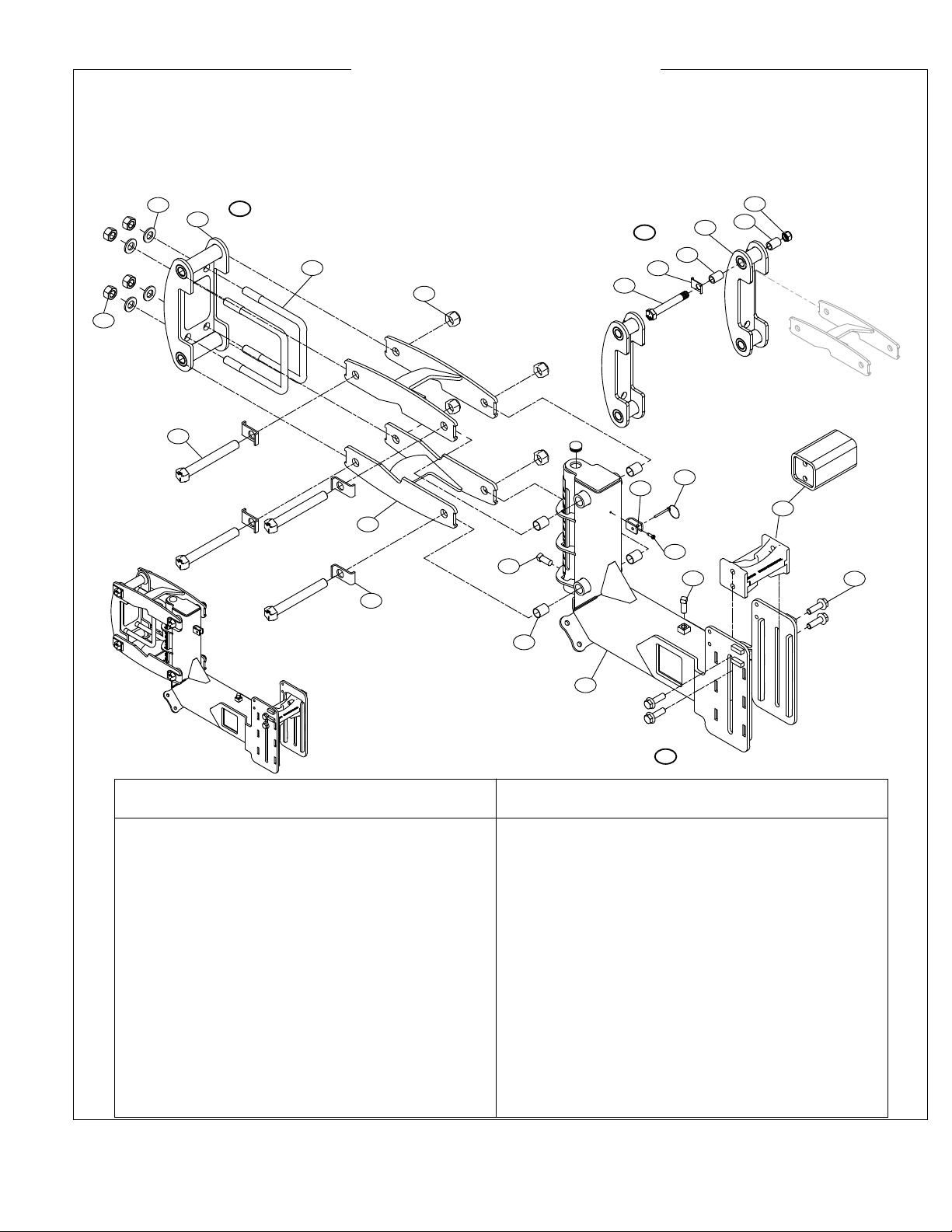
A. Wrap Around Clamp
1. 602-1635Z Bolt, Pivot 1”x8-1/4“ (Gr 5) ZP 4
2. 624-110 Bushing, 1x1-1/8x1-1/2” (Plastic) 8
3. 611-1401Z Nut, Hex ZP 7/8“ 4
4. 689-232S Bracket, 7” Wrap Around 1
5. 613-1603Z Nut, Hex Nylock ZP 1” Striptill 4
6. 689-208 Bolt Retainer, Striptill 4
7. 689-234S Linkage Arm, Wrap Striptill 2
8. 610-0047 U-Bolt, 7/8” For 7”x7” (Gr 5) ZP 2
9. 616-1403Z Washer, Flat 7/8” S.A.E. Hard ZP 4
10. 789-204 Tail Gang, 888 Cultivator 1
B. 789-204 Tail Gang Assembly
(Includes 11-16)
11. 301-357 Clevis, Handle Retainer ZP 1
12. 617-103 Klik Pin, 1/4 x 1-1/2” 1
13. 605-0406Z Screw,Hex Washer HD.12-14X3/4" ZP 1
14. 606-1010Z Set Screw, Square Head 5/8”x2-1/2” ZP 1
15. 606-1006Z Set Screw, Square Head 5/8”x1-1/2” ZP 1
17. 689-244T Clamp, Chisel Shank Mount 888 1
689-244 Tube, Tooling Mount 888 Cultivator
(Optional no-guide mount for 1x3 shank)
18. 603-1008Z Bolt, Flange Head 5/8”x2” (Gr 5) ZP 4
D. Split Wrap Around Clamp
26. 689-233S Bracket, 7” Split Wrap Around 2
27. 602-1620Z Bolt, HCS 1”x5” (Gr 5) ZP 4
Note: Four 1x5” Bolts for front part of
clamp, plus two 1x8-1/4” (item #1) for rear as
in other clamps and a total of 6 nuts (item #5).
(806) 745-0384 705 E. SlatonRd. P.O. Box3338 Lubbock, TX 79452
BIGHAM BROTHERS, INC.
Model 888 Cultivator
Parts Breakdown
760-808, 760-809 Gang Bundle, (Wrap and Wrap-Split Clamps) Model 888 Cultivator
Model Years 2012 Through Current
1
2
3
4
6
7
8
9
10
11 12
13
14
15 18
A
B
D26
27
5
5
2
2
6
17

Page 14
Form # B12-18C
(806) 745-0384 705 E. Slaton Rd. P.O. Box 3338 Lubbock, TX 79452
BIGHAM BROTHERS, INC.
Qty. Req. Per Assy.
Ref# P/N Description (* As Required)
Qty. Req. Per Assy.
Ref# P/N Description (* As Required)
2. 624-110 Bushing, 1x1-1/8x1-1/2” (Plastic) 8
3. 611-1401Z Nut, Hex ZP 7/8“ 4
6. 689-208 Bolt Retainer, Striptill 4
8. 610-0047 U-Bolt, 7/8” For 7”x7” (Gr 5) ZP 2
9. 616-1403Z Washer, Flat 7/8“ (SAE L9 Hard) ZP 4
10. 789-204 Tail Gang, 888 Cultivator 1
B. 789-204 Tail Gang Assembly
(Includes 11-16)
11. 301-357 Clevis, Handle Retainer ZP 1
12. 617-103 Klik Pin, 1/4 x 1-1/2” 1
13. 605-0406Z Screw,Hex Washer HD.12-14X3/4" ZP 1
14. 606-1010Z Set Screw, Square Head 5/8”x2-1/2” ZP 1
15. 606-1006Z Set Screw, Square Head 5/8”x1-1/2” ZP 1
17. 689-244T Clamp, Chisel Shank Mount 888 1
689-244 Tube, Tooling Mount 888 Cultivator
(Optional no-guide mount for 1x3 shank)
18. 603-1008Z Bolt, Flange Head 5/8”x2” (Gr 5) ZP 4
C. Rear Mount Clamp
19. 689-200 Mount Angle, Universal 2
20. 689-206 Linkage Arm 2
21. 686-992 Bracket, 7” Mount Support 2
22. 602-1640Z Bolt, HCS 1”x10” (Gr 5) ZP 1
23. 602-1638Z Bolt, HCS 1”x9-1/2” (Gr 5) ZP 2
24. 602-1636Z Bolt, HCS 1”x8-1/2” (Gr 5) ZP 1
25. 614-1606Z Nut, Hex Nylock Jam ZP 1” 4
(806) 745-0384 705 E. SlatonRd. P.O. Box 3338 Lubbock, TX 79452
B
IGHAM BROTHERS, INC.
Model 888 Cultivator
Parts Breakdown
760-807 Gang Bundle (Rear Mount), Model 888 Cultivator
Model Years 2012 Through Current
(Round Height Adjustment Tube)
10
11
12
13 14 18
17
B
C
22
2
6
19
20
21
8
23
23
24
3
9
2
25
15
(806) 745-0384 705 E. Slaton Rd. P.O. Box 3338 Lubbock, TX 79452
Page 15
Form # B12-18C
BIGHAM BROTHERS, INC.
Qty. Req. Per Assy.
Ref# P/N Description (* As Required)
Qty. Req. Per Assy.
Ref# P/N Description (* As Required)
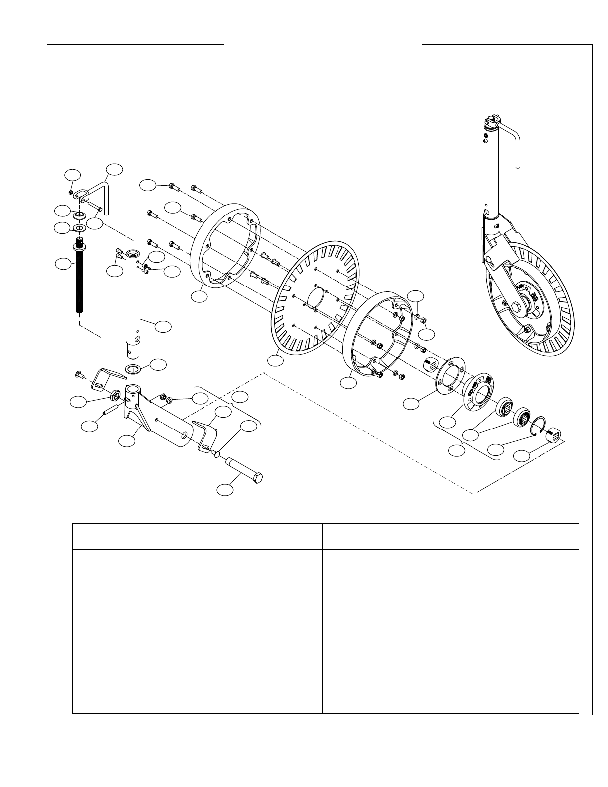
1. 627-773 Hub/Brg. Assy., Coulter Strip Till 1
2. 622-057 Bearing, 1-1/8" Sq W208PP5 2
3. 627-010 Snap Ring, Disc Bedder Housing 1
4. 627-772 Hub, Coulter Strip-Till 1
5. 610-0061 Axle, 1.209"X 6.25" Usbl. 1
6. 689-210 Spacer, Coulter Hub, Striptill 2
7. 660-141C Depth Band, 2x14 for 20” Blade 2
8. 630-012 Blade, Fluted 20“x4.5mm 4 Hole 1
9. 607-0804 Bolt, Flange(NF) 1/2x1-1/4” (3/4 HD) 4
10. 601-0806Z Bolt, HCS 1/2“x1-1/2” (Gr 2) ZP 6
11. 615-0800Z Washer, Lock ZP 1/2“ 6
12. 611-0801Z Nut, Hex ZP 1/2” (Gr 5) 6
14. 614-1800M Nut, Hex Nylock Jam 1-1/8" 1
15. 689-267 Stinger, Adjustable Swivel Coulter 1
16. 689-212 Screw Jack Stud, 1”x14-3/8” 1
17. 602-0610Z Bolt, HCS 3/8”x2-1/2” (Gr 5) ZP 1
18. 613-0600Z Nut, Hex Nylock ZP 3/8” 1
19. 624-112 Bushing, 1x1-1/4x9/16” W/HD 1
20. 624-113 Washer, Nylon 2”ODx1”IDX.125” 1
21. 689-222 Latch, Coulter Crank 1
22. 689-239R Yoke Weldment, Pivot Coulter 1
27. 617-062 Pin,Roll 1/2"x3" (ZP) 1
28. 616-1990 Washer, 2-1/2"ODx1-3/4"IDx10GA. 1
29. 689-272 Spacer, Coulter Hub 3/16” 1
30. 607-0603 Cap Screw, Socket 3/8“-16x1/2” 3
31. 617-009 Fitting, Grease 1/4“-28 UNF 1
32. 617-006 Adapter, Striptill 1/4” Zerk 1
Optional
23. 889-121 Scraper Kit, Adj. Coulter Striptill -
24. 686-993 Scraper, Adj. Coulter Striptill 2
25. 604-0806Z Bolt, Carriage 1/2”x1-1/2” (Gr 5) ZP 2
26. 614-0801Z Nut, Hex Serrated Flange 1/2” 2
Model 888 Cultivator
Parts Breakdown (Swivel Coulter Bundle with Depth Band)
789-319 Adjustable Swivel Coulter Assembly
Model Years 2012-Current (Round Height Adjustment Tube)
2
13
4
5
6
7
7
8
9
10
15
24
23
25
26
(806) 745-0384 705 E. SlatonRd. P.O. Box 3338 Lubbock, TX 79452
BIGHAM BROTHERS, INC.
16
19
20
21
18
17
22
28
27
11
12
14
30
31
32
29
Page 16
Form # B12-18C
(806) 745-0384 705 E. Slaton Rd. P.O. Box 3338 Lubbock, TX 79452
BIGHAM BROTHERS, INC.
Qty. Req. Per Assy.
Ref# P/N Description (* As Required)
Qty. Req. Per Assy.
Ref# P/N Description (* As Required)
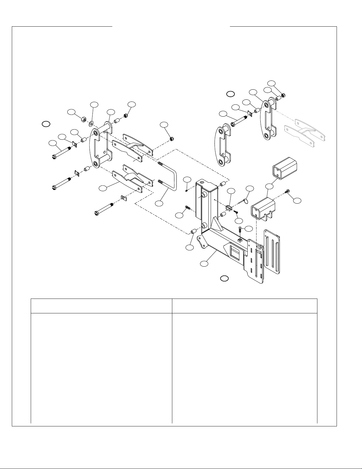
A. Wrap Around Clamp
1. 602-1635Z Bolt, Pivot 1”x8-1/4“ (Gr 5) ZP 4
2. 624-110 Bushing, 1x1-1/8x1-1/2” (Plastic) 8
3. 611-1401Z Nut, Hex ZP 7/8“ 4
4. 689-232S Bracket, 7” Wrap Around 1
5. 613-1603Z Nut, Hex Nylock ZP 1” Striptill 4
6. 689-208 Bolt Retainer, Striptill 4
7. 689-234S Linkage Arm, Wrap Striptill 2
8. 610-0047 U-Bolt, 7/8” For 7”x7” (Gr 5) ZP 2
9. 616-1403Z Washer, Flat 7/8” S.A.E. Hard ZP 4
10. 789-204 Tail Gang, 888 Cultivator 1
B. 789-204 Tail Gang Assembly
(Includes 11-16)
11. 301-357 Clevis, Handle Retainer ZP 1
12. 617-103 Klik Pin, 1/4 x 1-1/2” 1
13. 605-0406Z Screw,Hex Washer HD.12-14X3/4" ZP 1
14. 606-1010Z Set Screw, Square Head 5/8”x2-1/2” ZP 1
15. 606-1006Z Set Screw, Square Head 5/8”x1-1/2” ZP 1
16. 617-008 Zerk, 1/8 NPT Threaded 1
17. 689-244S Tube, Chisel Shank Mount 888 1
689-244 Tube, Tooling Mount 888 Cultivator
(Optional no-guide mount for 1x3 shank)
18. 603-1008Z Bolt, Flange Head 5/8”x2” (Gr 5) ZP 4
D. Split Wrap Around Clamp
26. 689-233S Bracket, 7” Split Wrap Around 2
27. 602-1620Z Bolt, HCS 1”x5” (Gr 5) ZP 4
Note: Four 1x5” Bolts for front part of
clamp, plus two 1x8-1/4” (item #1) for rear as
in other clamps and a total of 6 nuts (item #5).
(806) 745-0384 705 E. SlatonRd. P.O. Box3338 Lubbock, TX 79452
B
IGHAM
B
ROTHERS,
I
NC.
Model 888 Cultivator
Parts Breakdown
760-808, 760-809 Gang Bundle, (Wrap and Wrap-Split Clamps) Model 888 Cultivator
Model Years Through 2012
(Square Height Adjustment Tube)
1
2
34
5
6
7
8
9
10
11 12
13
14
15
16
18
17
A
B
D26
27
5
5
2
2
2
6

(806) 745-0384 705 E. Slaton Rd. P.O. Box 3338 Lubbock, TX 79452
Page 17
Form # B12-18C
BIGHAM BROTHERS, INC.
Qty. Req. Per Assy.
Ref# P/N Description (* As Required)
Qty. Req. Per Assy.
Ref# P/N Description (* As Required)
2. 624-110 Bushing, 1x1-1/8x1-1/2” (Plastic) 8
3. 611-1401Z Nut, Hex ZP 7/8“ 4
6. 689-208 Bolt Retainer, Striptill 4
8. 610-0047 U-Bolt, 7/8” For 7”x7” (Gr 5) ZP 2
9. 616-1403Z Washer, Flat 7/8“ (SAE L9 Hard) ZP 4
10. 789-204 Tail Gang, 888 Cultivator 1
B. 789-204 Tail Gang Assembly
(Includes 11-16)
11. 301-357 Clevis, Handle Retainer ZP 1
12. 617-103 Klik Pin, 1/4 x 1-1/2” 1
13. 605-0406Z Screw,Hex Washer HD.12-14X3/4" ZP 1
14. 606-1010Z Set Screw, Square Head 5/8”x2-1/2” ZP 1
15. 606-1006Z Set Screw, Square Head 5/8”x1-1/2” ZP 1
16. 617-008 Zerk, 1/8 NPT Threaded 1
17. 689-244S Tube, Chisel Shank Mount 888
689-244 Tube, Tooling Mount 888 Cultivator 1
(Optional no-guide mount for 1x3 shank)
18. 603-1008Z Bolt, Flange Head 5/8”x2” (Gr 5) ZP 4
C. Rear Mount Clamp
19. 689-200 Mount Angle, Universal 2
20. 689-206 Linkage Arm 2
21. 686-992 Bracket, 7” Mount Support 2
22. 602-1640Z Bolt, HCS 1”x10” (Gr 5) ZP 1
23. 602-1638Z Bolt, HCS 1”x9-1/2” (Gr 5) ZP 2
24. 602-1636Z Bolt, HCS 1”x8-1/2” (Gr 5) ZP 1
25. 614-1606Z Nut, Hex Nylock Jam ZP 1” 4
(806) 745-0384 705 E. SlatonRd. P.O. Box3338 Lubbock, TX 79452
BIGHAM BROTHERS, INC.
Model 888 Cultivator
Parts Breakdown
760-807 Gang Bundle (Rear Mount), Model 888 Cultivator
Model Years Through 2012
(Square Height Adjustment Tube)
10
11 12
13
14
15
16
18
17
B
C
22
2
6
19
20
21
8
23
23
24
3
9
6
2
25

Page 18
Form # B12-18C
(806) 745-0384 705 E. Slaton Rd. P.O. Box 3338 Lubbock, TX 79452
BIGHAM BROTHERS, INC.
Qty. Req. Per Assy.
Ref# P/N Description (* As Required)
Qty. Req. Per Assy.
Ref# P/N Description (* As Required)
1. 627-773 Hub/Brg. Assy., Coulter Strip Till 1
2. 622-057 Bearing, 1-1/8" Sq W208PP5 2
3. 627-010 Snap Ring, Disc Bedder Housing 1
4. 627-772 Hub, Coulter Strip-Till 1
5. 610-0061 Axle, 1.209"X 6.25" Usbl. 1
6. 689-210N Spacer, Coulter Hub, Striptill 2
7. 660-141 Depth Band, 2x14 for 20” Blade 2
8. 630-012 Blade, Fluted 20“x4.5mm 4 Hole 1
9. 607-0805 Bolt, Flange(NF) 1/2x1-1/4” (3/4 HD) 4
10. 601-0806Z Bolt, HCS 1/2“x1-1/2” (Gr 2) ZP 6
11. 615-0800Z Washer, Lock ZP 1/2“ 6
12. 611-0801Z Nut, Hex ZP 1/2” (Gr 5) 6
14. 614-1800M Nut, Hex Nylock Jam 1-1/8" 1
15. 689-246 Stinger, Adjustable Swivel Coulter 1
16. 689-212 Screw Jack Stud, 1”x14-3/8” 1
17. 602-0610Z Bolt, HCS 3/8”x2-1/2” (Gr 5) ZP 1
18. 613-0600Z Nut, Hex Nylock ZP 3/8” 1
19. 624-112 Bushing, 1x1-1/4x9/16” W/HD 1
20. 624-113 Washer, Nylon 2”ODx1”IDX.125” 1
21. 689-222 Latch, Coulter Crank 1
22. 689-239R Yoke Weldment, Pivot Coulter 1
27. 617-062 Pin,Roll 1/2"x3" (ZP) 1
28. 616-1990 Washer, 2-1/2"ODx1-3/4"IDx10GA. 1
Optional
23. 889-121 Scraper Kit, Adj. Coulter Striptill -
24. 686-993 Scraper, Adj. Coulter Striptill 2
25. 604-0806Z Bolt, Carriage 1/2”x1-1/2” (Gr 5) ZP 2
26. 614-0801Z Nut, Hex Serrated Flange 1/2” 2
Model 888 Cultivator
Parts Breakdown (Swivel Coulter Bundle with Depth Band)
789-317 Adjustable Swivel Coulter Assembly
Model Years 2011-Current
B
B
L
u
b
b
o
c
k
,
T
X
6
2
7
-
7
6
0
2
13
4
5
6
6
7
7
8
9
10
11
12
14
15
24
23 25
26
(806) 745-0384 705 E. SlatonRd. P.O. Box 3338 Lubbock, TX 79452
BIGHAM BROTHERS, INC.
16
19
20
21
18
17
22
28
27


