4mm
4
Wood dowel (4x30mm)
2
1
Steel wire (0.5x3000mm)
Steel wire (0.5x3000mm)
U-style wire (3mm)
Securely glue together. If coming off during flights, you 'll
lose control of your airplane which leads to accidents!
U-style wire (3mm)
1
Stab joiner(12x230mm)
6
Pin hinge(24x24mm)
4
Matal douel (4x30mm)
1
Rib template (2mm ply)
2mm ply
2
1
Steel wire (0.5x3000mm)
U-style wire (3mm)
4mm
1
Rib template (2mm ply)
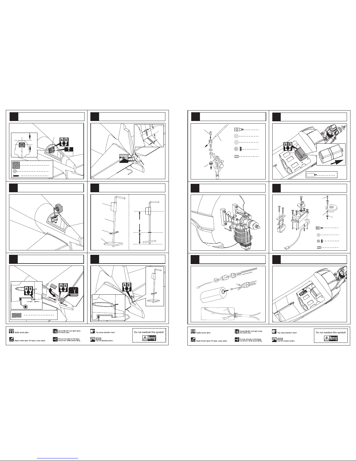
According to the rib template drill holes to the tail of
fuselage as below.
1
Stab joiner(12x230mm)
Drill two holes at the stabilizer root base on rib template
and epexy the wood dowel in them.
connect the fullarm on elevator with steel wire as below.
Install the U-style wire to appropriate position in the tail of
fuselage and assemble the stabilizer to fuselage as illustration.
Drill holes to appropriate position in the stabilizer .
39
40
41
42
43
8
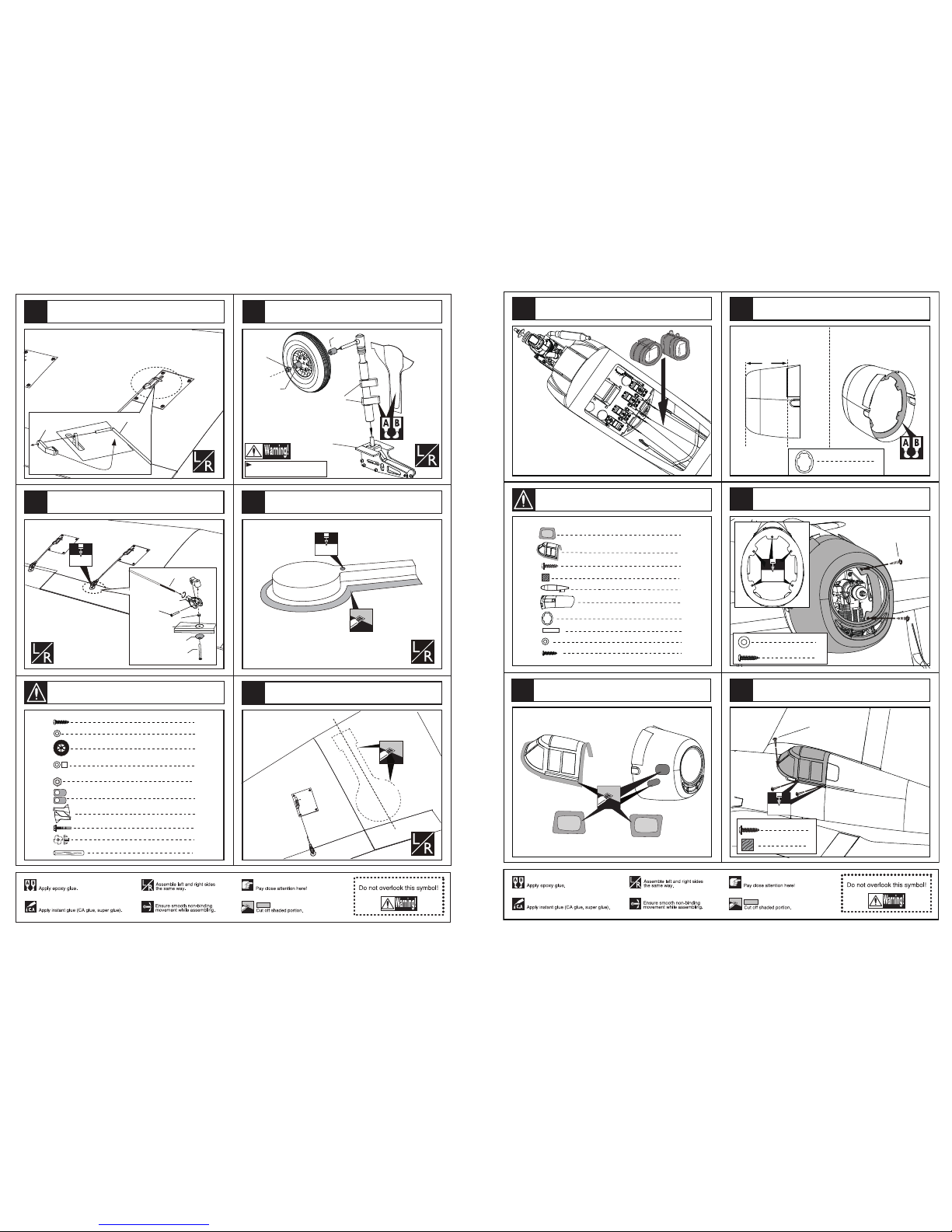
Accessory list for the coming installation steps.
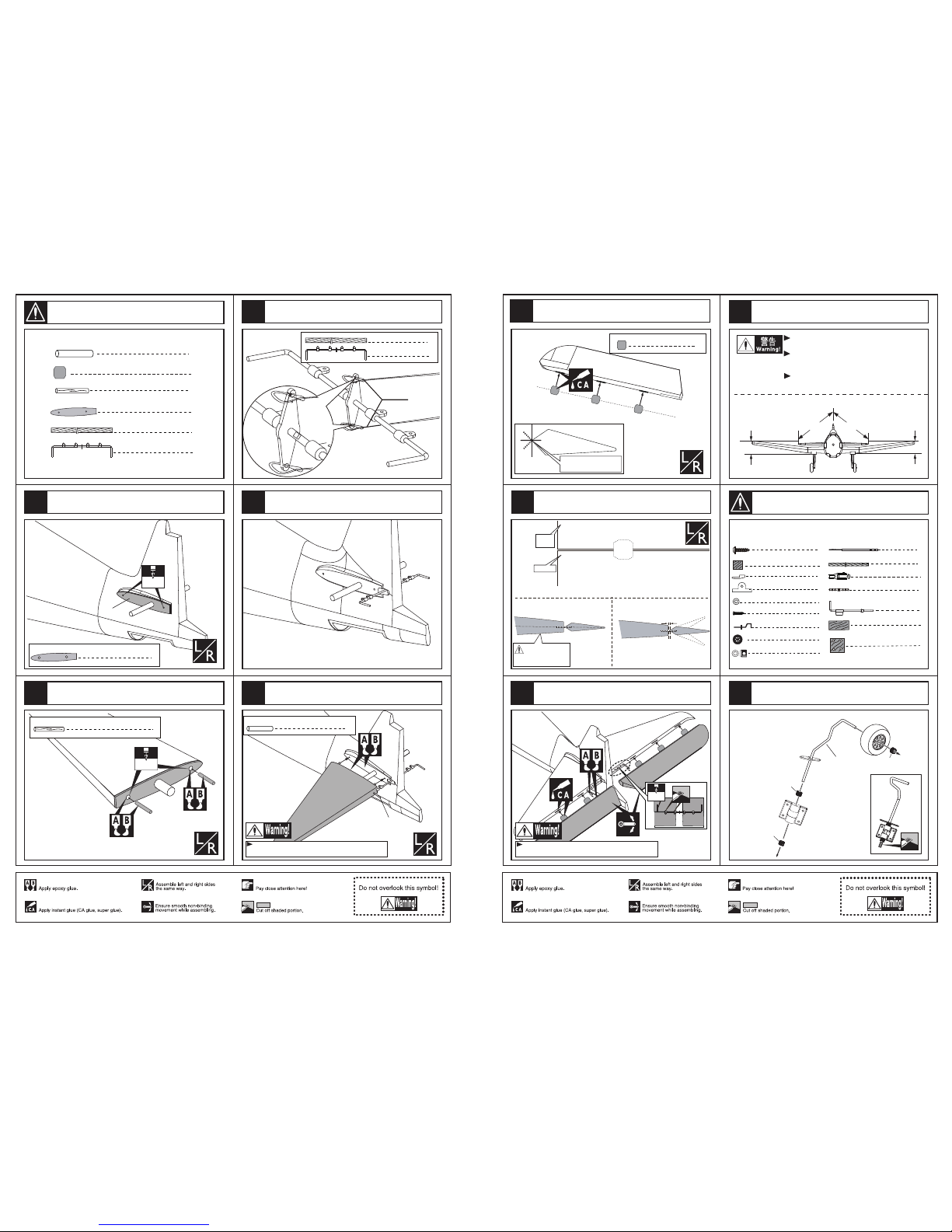
Collar
Tail landing gear
Collar
Collar
3
1
Nose arm(3mm)
Collar (3mm) 3
1
1
Tail landing gear(3mm)
Tail wheel (45mm)
1
Retainer
Rod (2X257mm) 1
TP Screw(3x20mm)
Washer (3x6mm)
4
4
2
Steel wire (0.5x3000mm)
1
Clevis
1
Tail landing gear(3x105mm)
Pin hinge(2.5x48mm)
Ply (35x20x3mm) 1
8
TP Screw (2.3x8mm)
Ply (15x15x3mm) 8
Elevator
1mm
Trailing
edge
Make sure they are in
the right position while
installing.
Securely glue together. If coming off during flights, you 'll
lose control of your airplane which leads to accidents!
3mm
Make sure hinges are
mounted in the same line.
6
Pin hinge(24x24mm)
Glue the elevator to the stabilizer by CA glue
and epoxy glue.
Apply instant type CA glue to elevator and pin hinge.
Keep some space about 1mm width between
elevator and tailing edge.
Ply (6mm) 1
B'
AA'
B
Make sure to glue securely.
If not properly glued, a failure in flight may occur.
Temporarily fasten down the main wing and
check its correct position.
Securely glue together.If coming off during flights,
you'll lose control of your airplane which leads
to accidents!
A=A'
B=B'
Assembly of the stabilizer.
Assemble the tail landing gear to the wheel steeling
mounts as below.
46
47
48
9
44
Accessory list for the coming installation steps.
45