bikel MPe V5 User manual
MPe COMPUTER
USER MANUAL
for use in all e-vehicles, and especially for e-bikes.
ul. Lipowa 17A/4
63-000 Środa Wlkp. / Pola d
Pho e: (+48) 733 44 30 33
e-mail: i fo@ebikecomputer.com
Website: https://ebikecomputer.com
Stay tu ed:
facebook: bikel.pl
instagram: bikel.pl_marek
youtube: bikel pl
Copyright © 2020
MPeV5 - safety otes for i stallatio a d use

By i stalli g MPe i your vehicle, you agree to the comme ts below a d accept them. If You disagree or You do 't
u dersta d a y of them, DO NOT i stall the MPe computer i to vehicle!
Ge eral i stallatio otes
•The MPe on-board computer is not an motor speed controller. To get motor running, an external controller is needed.
•If the motor controller is incorrectly set, the cranks can turn backwards! e sure to keep the wheel in the air during the first start and watch out for knees and cables
that may get caught in the cranks!
•When you use the virtual throttle function (you connected MPe in place of the throttle input in the controller), be sure to keep your wheel in the air during the first start-
up, because an incorrectly set controller or Mpe computer can cause spontaneous driving of the vehicle!
•Do not mount the "PowerPC " power module in tight places, between other components, because from vibration, the insulation may wipe and a short circuit in the
installation may occur.
•The vehicle should have a brake sensor installed and this is checked when the MPe system is turned on (symbol *). To drive, briefly press the brake to confirm that
the safety system is working properly.
•The MPe device must not be exposed to water.
•Max. the display cable length is 1.5m. Above this length, the display may not work.
•Displays may have a different shade of white between them and this can be seen when you look at two displays placed side by side simultaneously.
•Data is automatically saved when it is stopped (speed = 0km / h). If you turn MPe off while driving, the data may not be saved since the last stop.
•For FOC controllers (e.g. Sabvoton), the cruise control function may not work correctly due to the current throttle characteristics of the controller.
Notes o co ecti g wires to the MPe motherboard
•The cables in the PowerPC module and in the display module have the same colors - pay special attention when connecting!
•The MPe computer has no protection against reverse polarity - beware of battery + a d - whe co ecti g! - A SHORT CIRCUIT AND A BURNING
INSTALLATION CAN BE MADE!
•The negative battery terminal - in connector No. 4 must always be connected, the switch should be mounted on the positive + connector on connectors 1 and 2 of
the motherboard!
•First, co ect the cables from the "PowerPCB" module to the motherboard, a d the to the battery! Otherwise, the cables may short-circuit!
•Make sure that o si gle „wire hair” goes i to the adjace t co ector! The i stallatio may be short-circuited!
•Do not connect to Mpe motherboard any device other than described in the manual.
•You may not power anything other than described in the manual! (using the internal 5V converter of the MPe device).
•Do not exceed the supply voltage - max 150V DC.
•Do not connect under the switch circuit (pin 2) devices whose total current consumption exceeds 1.5A.
•When placing the cable in the motherboard connector, make sure the connector 'lift' is completely lowered.
•Do not over tighten the screws on the motherboard connectors, as you may damage the wire or the screw thread.
•After placing the cable in the motherboard connector and tightening the screw, lightly move the cable to make sure it is tight.
•e sure to secure the cable with a cable tie (to the housing tab) so that it does not come loose from the motherboard connector.
Notes o usi g the PAS fu ctio (pedali g assist with cade ce se sor)
•The bikel.pl company guarantees the efficiency of the product and makes every effort to ensure that the function works properly. However, it is not possible to predict
every configuration in which the PAS support function will be used and to guarantee correct operation in every configuration.
•When installing the PAS function, be sure to install and use the brake sensor to disengage the drive in an emergency!
•Some PAS sensors on the market also work when turning the cranks backwards!
•When the PAS function is installed, turning the cranks backwards can also start the motor! The start speed must not be set less than 3 km / h.
•Pushing the bicycle backwards makes the cranks spin. Reverse operation of some PAS sensors and setup of too low start speed may result in starting the motor in
forward direction!
•Heavy constructions may have a problem with PAS operation in up to 250W mode due to high power consumption and high starting and rolling resistance.
Temperature readi g
•The temperature of the overheating protection should be set, also the bimetallic thermostat should be carefully added to the controller ignition circuit.
•Different temperature sensors show different reading accuracy.
•Reading accuracy for the KTY83 sensor is +/- 10 degrees C due to the characteristics of the sensor.
•Reading accuracy for the LM35 +/- 5 degrees C sensor and only positive temperatures.
•Do not connect MPe and controller (e.g. Sabvoton) to the same temperature sensor in the engine (separate hall sets do not have different sensors, they have one and
the same sensor, but with two (the same) wires, going separately to two sets of hall wires ).
•y default, the T1 temperature is provided for the motor and has a disconnection threshold set at 145 degrees C.
•y default, the T2 temperature is provided for the controller and has a disconnection threshold of 65 degrees C.
•For MPe to protect the vehicle against overheating (disconnect the drive), the throttle must be connected to MPe and Mpe must be connected to the controller in
place of the throttle.
Disposal of used equipme t
•the used device (i.e. MPe computer and its subassemblies) should be properly disposed of in specially designated containers for electronics. It is
forbidden to put it together with other waste.
•Failure to comply with this requirement will result in a potential risk to the environment or human health.
Reuse and recycling of used equipment and components is not recommended by the manufacturer. They should be disposed of in suitable containers.
Connecting the device to the vehicle installation
ALL ATERIALS ALSO ON YOUTUBE CHANNEL:
BIKEL PL
Whe co ecti g the cables to the mai board co ectors, the battery ca ot be co ected to the PowerPCB module.
Failure to comply with this otice may result i a short circuit, which may result i electric shock, bur s or fire.
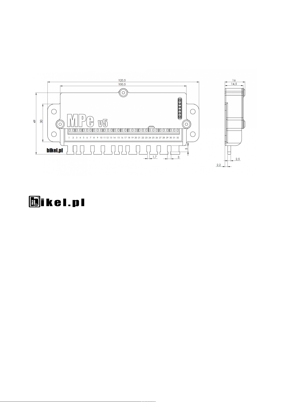
When connecting, use the diagram provided with this manual. On the main board, connectors from 1 to 32 are numbered, and with each module in the diagram, the
pins are numbered so that the digit symbolizing the connector number is assigned to the specific pin, with the specific module.
1. First, connect the PowerPC module (power supply and current measurement module) to connectors 3,4,5,6,7. The maximum supply voltage is 150V
DC.
Whe co ecti g thi , colored PowerPCB cables to the Mpe motherboard co ectors, the device ca ot be co ected to the battery !!! High-
curre t plugs are supplied delivered secured with cable ties to preve t u wa ted co ectio to the battery.
2. Then connect the switch circuit to connectors 1 and 2.
Whe co ecti g these cables, the device must ot be co ected to the battery!
3. When the power supply, i.e. the PowerPC module (points 2 and 3) is connected, you can connect the display to connectors 8,9,10,11,12,13.
When connecting these cables, the device should be turned off.
4. A speed sensor should be connected to connectors 14 and 15. (Alternatively, only to connector 14 when using a hall sensor in the motor).
When connecting these cables, the device should be turned off.
5. Connectors 16 to 32 are optional and do not need to be connected, however it is recommended to connect them to use all the functions of the device.
For detailed connection instructions, see bikel.pl
When connecting these cables, the device should be turned off.
6. Finally, you can connect the PowerPC module to the battery.
Pay special atte tio that the battery plus is co ected to the cable marked with "+" o the plug a d red shri k tube!
Whe co ecti g to the battery, the MPe device should be tur ed off (pi s 1, 2 o the motherboard ope )
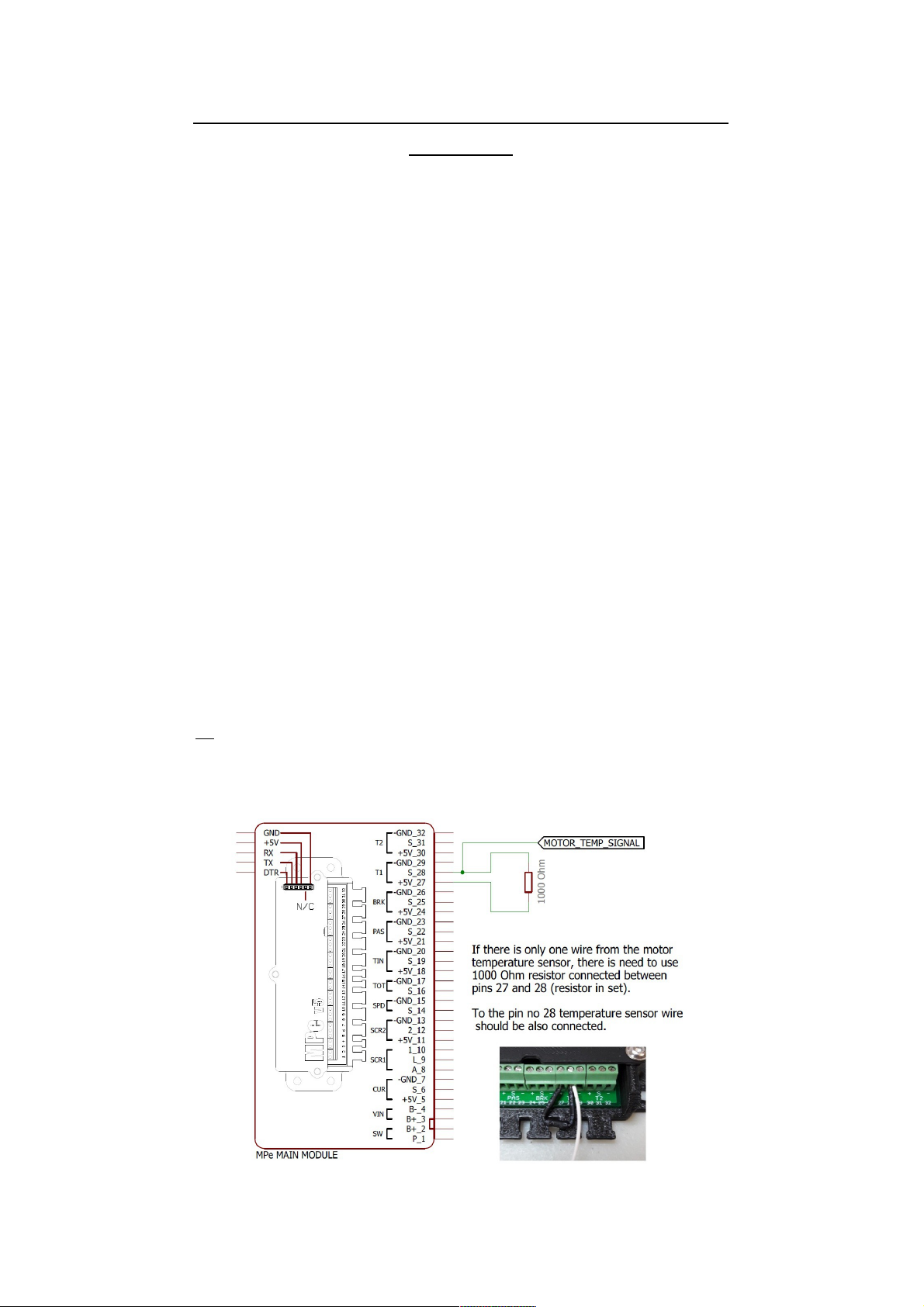
+ 5V must ot be co ected betwee the motor co troller a d the MPe mai board. The o ly allowed combi atio is the GND commo grou d.
Information on connecting an engine temperature sensor in which one wire has a common ground with hall sensors.

MPeV5 - display scree s:
Herei after, the followi g abbreviatio s will be used:
TBSP - Top Butto , Short Pressed
TBPH - Top Butto Pressed a d Hold
LBSP - Lower Butto , Short Pressed
LBPH - Lower Butto Pressed a d Hold
O each scree (except the co figuratio scree ):
TBSP - cha ge to the ext scree
LBSP - cha gi g the scree to the previous o e
SCREEN 1:
•speed
•battery level
•assist level
•the distance to go, on the remaining battery (RANGE)
•brake and cruise control use indicator (*)
•T PH - assist mode is changed to a higher one. When active cruise control - increasing the speed.
•L PH - assist mode is changed to a lower one. When active cruise control - decreasing the speed.
SCREEN 2:
•MX: Maximum registered speed, during the daily distance [km / h or mph]
•TR: Daily distance (trip) [km or mi]
•AV: Average speed during the daily distance [km / h or mph]
•MT: number of minutes in motion during the daily distance [min]
•T PH - no action
•L PH - zeroing all values of screen 1 and PM value from screen 3 and IM and WK values from screen 4
SCREEN 3:
•U: attery voltage [V]
•I: Current drawn from the battery [A]
•Q: instant battery power [W]
•PM: Maximum registered power drawn from the battery during the daily distance [W]
•T PH - no action
•L PH - calibration / zeroing of the current sensor (I) (use only when connecting the MPe computer for the first time or when at standstill, the value (I)
does not indicate 0)
SCREEN 4:
•IM: Maximum recorded value of current consumed during the daily distance [A]
•WK: Average amount of Wh (watt-hours) consumed, per one kilometer of daily distance traveled [Wh / km]
•BC: attery capacity (entered in parameter no 2 in the configuration screen) [Ah]
•AU: number of Ah consumed (ampere-hours) from the battery, since the last charge [Ah]
•T PH - no action
•L PH - resetting the AU value, which results in resetting the battery charge indicator from screen 1 to full (also after fully charging the battery, this
operation is done automatically)

SCREEN 5:
•T1: Temperature on sensor 1 [stC or F]
•T2: Temperature on sensor 2 [stC or F]
•DS: Total distance traveled [km or mi]
•NC: number of battery charging cycles [pcs]
•T PH- no action
•L PH - no action
SCREEN 6:
•Clock
T PH - access to the configuration screen
L PH - clock setting (releasing and pressing the button again, reverses the time setting direction)
DESCRIPTION OF THE CONFIGURATION SCREEN:
The complete list of parameters ca be fou d o a separate page, compiled i the table.
ENTRY to the co figuratio scree : on the clock screen hold the top button.
EXIT from the co figuratio scree : keep pressing the button (lower or upper) until the underscore goes out of the screen.
TBSP * - change the value over the underscore by one greater
TBPH * - move the underscore indicating the value by one to the right
LBSP * - change the value over the underscore by one smaller
LBPH * - moves the underscore pointing to the value one to the left
* (abbreviations explained below the screen photography on previous page)
Description of selected basic configuration parameters (marked in gray on the full list):
Especially these parameters should be set so that the MPe device works correctly (i dividually i each vehicle).
Parameter o:
2 - attery capacity in Ah * 10 (ampere-hours). For example: for a 56.5Ah battery, enter 565 (56.5 * 10 = 565).
4 - Number of battery S sections (cells connected in series in the battery). For example: for a li-ion battery with a nominal voltage of 48V, enter 13 (13S).
3 - Wheel circumference in mm (wheel diameter [mm] * 3.14).
15 - Number of magnets in the motor for speed reading, with Mpe connected to the signal from the hall sensor. When using the reed switch on spokes, set the value
to 1.
26 - Number of magnets in the PAS sensor.
30/31 - Sensor type T1 0 = LM35, 1 = NTC10k, 2 = KTY83, 3 = NTC10k + 1kOhm resistor (common ground with halls), 4 = KTY83 + 1kOhm resistor (common ground
with halls).
11 - Direction of current sensor operation: if on screen 3 the "I" field indicates a negative value, change the value to the opposite.
41 - Direction of operation of the brake sensor: whether it is to be activated with the contacts closed or open.
43 - Deactivation of checking if a brake sensor is installed when starting the device (* symbol on screen 1).
21 - Road or off-road mode (off statutory). When "1" appears, only 3 PAS support modes (0,1,2,3) are active and the throttle control does not work. Setting "0":
activates modes 4 and 5 and the throttle lever. There is a shortcut to switch between road and off-road mode - pressing the brake and holding the bottom display
button (on screen 1)
0 - Firmware version of the MPe system. 5000 = 5.000, 5001 = 5.001 etc. (this value can only be changed by uploading a different firmware version).
Importa t
The throttle lever only works in off-road mode - the assist mode number is then in the white square (as can be seen on image with SCREEN 1 in this manual on
previous page)
There is a shortcut to switch between road and off-road mode - pressing the brake and holding the bottom display button (on SCREEN 1)
For the computer to allow the motor to run, everything must be properly configured, and in addition the following conditions must be met.:
-temperature in the range (incorrectly set sensor type may give bad readings), when no sensors set 0.
-calibrated current sensor, indicating current consumption at standstill 0A, and correctly set direction of current sensor operation.
versio 7
Table of contents
Popular Automobile Accessories manuals by other brands


ULTIMATE SPEED
ULTIMATE SPEED 279746 Assembly and Safety Advice

SSV Works
SSV Works DF-F65 manual

ULTIMATE SPEED
ULTIMATE SPEED CARBON Assembly and Safety Advice

Witter
Witter F174 Fitting instructions

WeatherTech
WeatherTech No-Drill installation instructions

TAUBENREUTHER
TAUBENREUTHER 1-336050 Installation instruction