BilJax 4527A Original instructions

ARTICULATE BOOM LIFT - Bil-Jax #4527A, .
45’ / 51’ Battery-Operated, Towable Unit .
2015 - “Operational and Safety Information”… .
from; TAYLOR RENTAL CENTER
1560 Hwy. 1 South / MLK Blvd. Greenville, MS. 38701, phone; (662) 335-3535
store hours; 7:00 am - 5:30 pm Monday thru Friday, 7:00 am - 11:00 am Saturdays
store email; trcgreenville@gmail.com, web site; taylorrentalgreenville.com
------------------------------ “Serving the Greater Delta Area since 1979” -----------------------------------
Like anything else at our location, each and every piece of equipment has an inherent risk of operator error that can .
lead to accidents and injury. An aerial work platform (AWP), like other equipment when properly used by skilled .
operators, is relatively safe. However, should an incident happen, the chances of a catastrophic accident are greater .
than with other equipment. This statement applies to our “Bil-Jax #4727A”, Battery .
Operated, Towable Articulated Boom Lift. We have tried to cover safety information and .
issues as we know them at this time. With that in mind, please take a few moments to go .
over the information printed below. These recommendations are from the equipment .
manufacturer, the rental industry, trade magazine articles, insurance companies and our .
own staff. We have compiled them to help to lessen the chances of accident or injury! .
While our “Operational and Safety” information only hits a “few high point” and contains .
“some” useful information, we strongly encourage you to take the time to read and review .
The “complete” manufacturer’s “Operation and Safety Manual”. TRC also encourages .
Reading and reviewing the safety publication; Statement of Best Practices for Workplace .
Risk Assessment and Aerial Work Platform Equipment Selection. This booklet was .
developed to aid the identification of workplace hazards, offer guidance for workplace .
risk assessment and implementing control measures and assists in the selection of the .
most appropriate AWP equipment for the work required. If you should have any questions,.
please stop and call TRC immediately at our store location; (662) 335-3535 or after hours .
at; (662) 822-1909 or (662) 822-1907. Never use “any equipment” in doubt! .
A. MACHINE’S INTENDED USE;
This “Towable Articulate Boom Lift” is designed for lifting one or two persons with small lightweight handheld items
(in a confined length - within the basket area). This unit may be used on “reasonable level” hard surfaces or hard
ground areas. The total weight of person or persons and small handheld items should not exceed 500 lbs. Do not
use this equipment for anything other than what the manufacturer’s intended use. This unit is not designed to
perform crane work, nor is it designed to be used as a support structure. If you have any questions on the
manufacture’s intended use or intentions, consult with TRC or reread the manufacturer’s “Operation and Safety
Manual”! Do not alter or modify this equipment in any way. Make sure the job work is matched to the intended use,
design and ability of the machine. Furthermore … this equipment is designed and manufactured in compliance with
the duties, responsibilities and standards set forth for manufacturers in the ANSI 92.2 standard in effect at the time
manufacturer. This equipment will meet or exceed applicable OSHA codes and ANSI A92.2 standards when used
in accordance with sections 7,8,9 & 10 of ANSI A92.2 and any other manufacturer’s recommendations.
B. MACHINE’S (RENTAL) DESCRIPTION;
Equipment;
TOWABLE, ARTICULATE BOOM LIFT; (TRC computer description; LIFT,BOOM ART - TOW 45’ - 51’); comes
equipped with the following; 1x - Manufacturer’s “Operator’s Manual”, 4x - Hydraulic Operated Outriggers,
1x - Battery Charger.
Accessory Rental Items;
SAFETY LANYARD; (TRC computer description; (LIFT, xa item SAFETY LANYARD); This is a “required item”.
We priced it separately because some of our customers have their own safety “harness” equipment.
EXTENSION CORD; (TRC computer description; (CORD, EXTENTION 12/3 - 20’); is priced separately. This is used
to charge the machine during it’s off hours. (this is the maximum length suggested by the manufacturer)
SAFETY BARRICADES and CONES; (TRC computer descriptions; (SAFETY BARICADE DRUM) and (SAFETY CONE -
18” reflective) are priced separately. We strongly suggest using these if you have vehicular or pedestrian
traffic nearby.
Related Merchandise / Resale Items;
2” TRAILER BALL; (TRC computer description; TRAILER, TOWING BALL - 2”); is priced separately. Customer
must use a 2” diameter with at least a 4,500 lb. or higher tow capacity.
BARRICADE SAFETY TAPE; (TRC computer description; SAFETY, BARRICADE TAPE); is priced separately. We
offer this in a yellow “Caution” Tape or a red “Danger” Tape. Both available in 300’ or 1,000’ lengths.
BARRICADE SAFETY FENCING; (TRC computer description; SAFETY, BARRICADE FENCING); 50’ fencing is
priced separately.
C. MACHINE SPECS; (for further information, see the Manufacturer’s “Operator’s Manual”, page; 11)
OPERATIONAL DATA; Maximum Platform Height; 45’, Working Height; 51’. Maximum Horizontal Outreach; 27’
(from Centerline; 27’, from Outrigger Footpad Edge; 21’). Rated Platform Capacity; 500 lbs. Maximum Occupants;
2. Turntable Rotation; 700 degrees Non-Continuous. Leveling Capacity; 12.5 degrees. Localized Pressure per
Outrigger. Function Speed; Boom Raise (Fast); 30-35 seconds, (Slow); 50-55 seconds. Boom Lower (Fast);
45-50 seconds, (Slow); 120-150 seconds. Boom Extended (Fast); 30-35 seconds, (Slow); 75-90 seconds.
Turntable Rotation; (Fast); 82-90 seconds, (Slow); 100-110 seconds. Platform Level; (Fast); 8-10 seconds,
2015 -BIL-JAX #4725A, “TOWABLE - ARTICULATE BOOM LIFT”- OPERATIONAL & SAFETY INFO…page 1 - 12

C. MACHINE SPECS; continued …
(Slow); 12-16 seconds. Outrigger Extended; 15-20 seconds, Retracted; 25-30 seconds. Operation Temperature
Range; -20 to 110 Fahrenheit (-29 to 43 Celsius).
INSTRUMENTATION (Buttons, Controls, Indicators, Switches, Etc.); Ground Control Station; (see Manufacturer’s
“Operator’s Manual”, pages; 14 & 15), Key Switch, Battery Conditional Indicator, Engine Start and Choke,
Display Panel, Emergency Stop Button, Boom Extend / Retract Buttons, Boom Raise / Down Buttons, Speed
Buttons, Platform Tilt Buttons, Boom Rotation Buttons, Outrigger Controls. Platform Control Station; (see
Manufacturer’s “Operator’s Manual”, pages; 16 & 17), Horn Button, Battery Condition Indicator, Emergency
Stop Button, Speed Buttons, Boom Rotation Buttons, Boom Raise / Down Buttons, Boom Extend / Retract
Buttons, Platform Tilt Buttons.
MOTOR; 24-volt
PARKING & TOWING BRAKES; Parking Brake; Standard Mechanical. Towing Brake; Mechanical Surge.
BATTERY; 4 x 6V 245 amp-hr.
ELECTRICAL;Charger; (Standard); 110/120-Volt.
FLUID CAPACITIES; Hydraulic System Capacity; 6.3-Gallons. Reservoir Capacity; 4.3-Gallons.
HYDRAULICS; Hydraulic Pressure; 3,000 psi. The Hydraulic System is filled with a HVI
Powerflow 32 with a Viscosity of 195.
LOCALIZED PRESSURE PER OUTRIGGERS; 25 psi per outrigger.
SOUND LEVEL; Standard DC mode - Ground 60 dB, Platform; 55 dB.
AUXILIARY “WORK” LINES;Build-in Air Line; (120 psi rating) 1/4” Male fitting at base - ground level, 1/4” Female
fitting at basket, Water line (3,000 psi rating) 3/8” Female fitting at base - ground level, 3/8” Male fitting at basket.
DIMENSIONS; (see specifications; page 11). Platform; Length; 2 ft., 6 inches, Width; 4 ft., Height; 3 ft., 7 inches.
Stowed; Length; 19 ft., 6 inches, Width; 5 ft., 6 inches, Height; 6 ft., 5 inches.
Outrigger Footprint; Length; 12 ft., 4 inches, Width; 11 ft., 4 inches, Footprint Diameter; 12.5 inches.
TIRES; Size; (front) 11 x 8 and (rear) ST 225/75 R15D, Air Pressure; Maximum (COLD) pressure; (rear); 55 psi.
TOWING; Rated Towing Speed; 65 mph. Trailer Ball Coupler size; requires a 2” trailer ball with a 5,000 lb., rated
Tow Capacity. Tongue Weight; 170 lbs.
OPERATING WEIGHT; approximately machine weight; 3,880 lbs.
D. WARNINGS;
Read these instructions thoroughly. Do not use this equipment until you have; (1.) you have read, received and
comprehend the instructions at the point of rental at TRC. (2.) You have been instructed by a “uniformed TRC”
employee on the machine’s safe operation. (3.) You have located the manufacturer’s operator’s manual (located
in the lift basket, in a black weatherproof container, to the right of the control console). Do not use this equipment
without the operator’s manual being in place on the machine. (4.) Until you have read and fully understand the
Manufacturer’s “Operation and Safety” Manual, including; (a.) you have read all safety decals on the machine,
(b.) and the operator understands the manufacturer’s intended use and safe operation of this equipment. The
operator’s manual must stay with the machine. It should always be available for the immediate use of the operator
at all times. Familiarity and proper training are required for the safe operation of this mechanical equipment.
Equipment operated improperly or by untrained personnel can be dangerous. Read the operating instructions in
the operator’s manual instructions and become familiar with the location and proper use of the controls. TRC also
keeps a copy of the manufacturer’s operators manual in store and it is available upon request. For our customer’s
safety and convenience, these instructions are available at our web site; www.taylorrentalgreenville.com. The
Manufacturer’s “Operator Manual” should be able to be viewed or printed from this site. Never allow “untrained”
operators or riders on this equipment. Never use this equipment in doubt. Do not alter, modify or change this
equipment in any way that would affect its original design or operation. Do not attempt to make repairs to this
equipment. Never operate this equipment in ways for which it is not intended. Failure to follow instructions can
result in death or serious bodily injury and/or damages.
E. PERSONAL SAFETY;
ANSI standards and Occupational Health and Safety Administration (OSHA) regulations require the use of
personal “fall protection” equipment with all boom-type AWPs. Any individual or individuals must wear a “safety
lanyard” (fall restrain) while in the lift’s basket at all times. Other appropriate items that should be considered are
proper clothing (avoid shorts and loose fitting clothing), hard hat, safety shoes (avoid slippery sole shoes), safety
glasses with side shields, impact goggles or face shield. Additional items such as heavy work gloves, hearing
protectors, reflective clothing, water repellent clothing, respirator or filter mask may or may not be recommended,
depending on the job requirements. Always match your safety equipment to the work being performed. Do not
wear rings, jewelry, bind long hair, etc. Avoid items that may catch in moving parts or be a distraction. The
operator should be physically and mentally fit. Avoid use of drugs or alcohol, items which can change the alertness
or coordination of the operator. Prescription and some over-the-counter drug users may need to seek medical
advice on whether or not they can safely operate this equipment without any side effects or safety issues.
Remember safety starts with you!
F. USAGE RESPONSIBILITIES;
CUSTOMER’S RESPONSIBILITIES; To exercise “sound judgment” and “good sense” when operating this equipment.
It is responsibility of the user of this equipment to follow all applicable ANSI, OSHA, Federal, State and local codes
and regulations that govern the safe operation of this equipment. It is the Customer’s responsibility to follow all
applicable federal, state and local codes and regulations pertaining to the safe use and operation of this aerial lift in
your application. The customer is responsible for all damages… including but not limited to abuse or improper use,
such things as; body damage, paint overspray, trailer tongue damage, tires & rims (road hazard), etc.) We ask that
the machine be returned clean … in other words, if it is beyond “normal work appearance”, charges will be accessed.
2015 -BIL-JAX #4725A, “TOWABLE - ARTICULATE BOOM LIFT”- OPERATIONAL & SAFETY INFO… page 2 - 12
F. USAGE RESPONSIBILITIES; continued …
SITE INSPECTION; Always inspect / survey your job site for potential hazards; untamped earth fill, unlevel
surfaces, overhead obstructions, overhead power lines, electrically charged conductors or wires, cables, etc.
(see work safety below). Check for uneven terrain, obstructions, debris, holes, grades, etc. Make sure that the
ground surface is capable of supporting the machine and any loads it may carry. Never operate lift on slopes
exceeding 12.5 degrees. Make sure all bystanders are cleared from the work area. Cordon off area around
the outriggers to keep personnel and other equipment away from it while it is in use. Use of safety fencing,
barricade tapes, warning signs, flashing lights are strongly recommended around the outer work site. Be aware
of potential hazards and what could happen.
SIMPLE SERVICE - MACHINE MAINTENANCE;
…on extended rentals (more than 1-day) or if conditions warranty, closer care maybe needed.
1. Daily Service Checks; The following Maintenance procedures should be performed daily or before each
Operation. (see the Manufacturer’s “Operator’s Manual”, pages; 26 - 29, for further instructions).
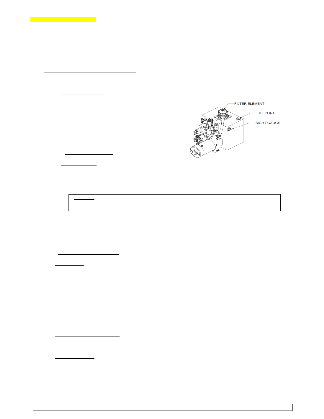
Hydraulic Fluid Level; The oil level “sight gage” should be Figure 4-2 Hydraulic Reservoir
“visually checked with the boom down and the trailer on
a level surface. When looking at the lift from the trailer
tongue end, the hydraulic reservoir will be on the left side
of the machine. It will be located directly under the side
cover. The hydraulic reservoir will be clearly marked and
the sight gauge will be recognizable. It will be facing
outward, located in the top left hand corner). The hydraulic
oil level should be visible in but not above the sight gauge.
If the hydraulic oil level is not visible to at least half way up
the sight gauge “contact TRC”… so that “we may correct”
the hydraulic fluid level. “Never attempt” to add hydraulic
fluid to this equipment.
Battery Charging;
** (see the Manufacturer’s “Operator’s Manual”, pages; 3-8).
** (recharging instructions are on page; 9 - of these instructions).
The DC boom lift batteries should be recharged after each 8-hour work shift or more often if needed.
When the lift is not in use, the batteries should be recharged at least once per week. The normal charge
time is 10 to 12-hours. If the battery charge is extremely low, a full charge may take up to 24-hours.
WARNING; Recharge the batteries in a “well ventilated” area only. Do not charge batteries near
fire, flame or other ignition sources. Batteries being charged may emit highly explosive hydrogen
gas. Failure to properly ventilate the charge gases may result in serious injury or death.
2. Weekly Service Checks; Inspect all electrical wiring for cuts, loose terminals, broken wiring, chafing or
corrosion. Inspect transport hitch components for damage. Inspect boom lift for missing, loose or damaged
hardware. Inspect hydraulic system components; including pump, motor and cylinders for damage, leaks,
loss of pressure or speed and unusual noise or vibration.
3. Monthly Service Checks; Contact TRC.
MACHINE INSPECTION;
1. “Overall Visually inspection”unit for damages or worn parts; check for cracked welds, trailer tongue,
hydraulic leaks, damaged wiring, loose wiring connectors, damaged outriggers, etc.
2. Decal Check; verify that all decals are in position and in plain site. (refer to Manufacturer’s “Operator’s
Manual”, section 5 for decal locations). If any decals are missing or have been damaged, contact TRC
immediately.
3. Controls and Indicators; verify that controls and indicators at ground and platform control stations
operate properly. (as defined in the Operator’s Manual, section 4).
1. Lower outriggers to level the boom lift.
2. Raise and extend all booms.
3. Press emergency stop button.
4. Verify that boom remains elevated and does not drift.
5. Pull stop button and lower the boom.
6. If either control station is unresponsive, contact TRC.
7. If display panel displays an error code, refer to (see the Manufacturer’s “Operation & Safety”
Manual, section 4, pages; 31-47), see Table 4-2 for error code definition and contact TRC.
4. Basket and Outrigger Shoes;
1. All parts should be in place and free from damage
2. Make sure these are free of mud, grease or any other slippery material to reduce possibility of
slipping.
5. Wheels and Tires; check air pressure (see the Manufacturer’s “Operator Manual”, maintenance, page; 26).
This is best done prior to work day when the tires are cold, not hot (see Specs above, for the correct
tire inflation pressure). Never inflate a tire beyond the maximum allowable pressure printed on the tire.
Make sure there are no missing or loose lug nuts on each wheel. Inspect the wheel rims for damage.
Never attempt any tire or wheel repairs, contact TRC where we may get a qualified tire mechanic to
service the tires and rims of this machine. If problems during transportation should occur (flats, blow
outs, etc.), contact TRC. Make sure any damaged tires on this equipment are saved for TRC inspection.
2015 - BIL-JAX #4725A, “TOWABLE - ARTICULATE BOOM LIFT”- OPERATIONAL & SAFETY INFO… page 3 - 12

F. USAGE RESPONSIBILITIES;
MACHINE INSPECTION; continued …
6. Hydraulic Leaks; This is best done by walking around the machine. Do not expose yourself to any potential
shear or pinch points. Check the hydraulic hose and fittings for leaks and damages daily. Always use
care when visual inspecting for hydraulic fluid. Hydraulic fluid under pressure can penetrate the skin or
eyes and cause serious injury. Always wear a face shield or safety goggles for eye protection whenever
you are operating or “visually” inspecting the machine. Always wear gloves but avoid touching hydraulic
fluids. Use cardboard to confirm hydraulic fluids on machinery. Dispose of cardboard in a responsible
manner. If any fluid is injected into the skin, it must be removed within a few hours by a doctor familiar
with this type injury. Do not operate this equipment if; damages occurs, leaks appear or if there are
any operational abnormalities or any controls malfunctioning. Stop immediately and contact TRC at
(662) 335-3535, (662) 822-1907 or (662) 822-1909.
WORK SAFETY; (see the Manufacturer’s “Operator’s Manual”, pages; 1-4 and 1-5).
ELECTRICAL; This machine is not insulated for use near electrical power lines and “DOES NOT” provide
protection from contact with or close proximity to any electrically charged conductor. Operator must maintain
safe clearance at all times (10 feet minimum) and always allow for platform movement such as wind induced
sway.
WARNING; The IPAF (International Powered Access Federation) states that an extended boom lift
should always be at least 50’ from electrical pylons and 30’ from cables on wooden poles. These
recommended safe distances meet or exceed those specified in ANSI standards and OSHA
requirements. Boom lifts are one of the safest ways of doing temporary work at heights, so the
burden is on “the operators” to stay safe near power lines and conductors are any other energized
source, etc. Electrocutions can be prevented thru proper planning, risk assessment and
management of work at height, including operator training and familiarization. Assume “EVERY
POWER LINE” is live. Always contact the power company before performing work near power lines.
IF machine contacts energized power lines, NEVER touch or operate until power lines are shut off.
Minimum Safe Approach Distances; (Consult the Manufacturer’s “Operator’s Manual”, pages; 1-4).
Voltage Range Minimum Safe Approach Distances
(Phase to Phase) (Feet) (Meters)
0 to 300 V ………………………. Avoid Contact
Over 300V to 50KV ……………….. 10’ 3.05
Over 50KV to 200KV ……………… 15’ 4.60
Over 200KV to 350KV ……………. 20’ 6.10
Over 350KV to 500KV ……………. 25’ 7.62
Over 500KV to 750KV ……………. 35’ 10.67
Over 750KV to 1000KV ………….. 45’ 13.72
Always position the lift far enough away from a power source to ensure that no part of the lift can accidently
reach into an unsafe area. This includes full extension of the boom through 360 degrees rotation.
OPERATIONAL USE; Always report any misuse of the equipment to the proper authorities. Horseplay is
prohibited. Stay clear of wires, cables, eves and other overhead obstructions. Make personnel aware and
keep them away from potential pinch points, shear points and from potential crush hazards as indicated by
machine decals attached to the machine. Keep the safety bar lowered at all times unless personnel are entering
or exiting the work platform. Always keep personnel and obstructions clear of the machine when repositioning
or operating the boom and basket. Cordon off the work area surrounding the outriggers to keep personnel,
vehicles and moving equipment away from the machine. Always exercise caution when rotating the boom
(slew) from the ground control station. Watch for personnel inside the radius of the turret and boom arm when
rotating the boom lift from the ground or platform controls. Keep a wide stance to help maintain sure footing
on the work platform. Keep the platform and all work areas free of debris.
WARNING; “Welding Information” … Never allow electrode contact with any part of the basket if
welding is being performed from the platform. Never use the machine as a ground for welding.
Never use without the outriggers fully extended, locked and firmly based. When on soft surfaces, always use
outrigger base plates. Never operate on a slope exceeding 12.5 degrees. Never override or by-pass the
manufacturer’s safety devices. Never attach a safety harness to an adjacent structure, pole or equipment while
working from the boom lift. Never release the outrigger locks or move with a person or materials on board.
Never release the outriggers or move the trailer with the boom extended. Never stand or sit on cage bars. Work
only within the work cage and do not lean out over the cage to perform work. The operator shall not use railings,
planks, ladders or any other devices in or on the work platform for achieving additional working height or reach.
Never allow ropes, electrical cords, hoses, etc., to become entangled in the equipment, especially when the
basket is being raised or lowered. Always make sure all tools and equipment are safely stowed. Do not exceed
load ratings by transferring loads to the basket at elevated heights. Never use cage to carry materials and never
allow overhang of materials when raising or lowering the basket. Never push or pull with the boom or basket
and never use the boom to lift any part of the trailer. Never use the boom or basket to place a “dead man” load
(to prop up other items) against any structure, materials or equipment. Never climb up or down a down boom.
Never leave the keys in the boom lift while unattended or not in use. Never leave an elevated platform unattended.
2015 - BIL-JAX #4725A, “TOWABLE - ARTICULATE BOOM LIFT”- OPERATIONAL & SAFETY INFO…page 4 - 12
F. USAGE RESPONSIBILITIES;
WORK SAFETY; continued …
MATERIAL SAFETY DATA SHEET - ITEMS; For Lead Acid Batteries, (see Manufacturer’s “Operation Manual”,
pages; 59-60). For Hydraulic Oil (Dextron III / Mercon Automatic Transmission Fluid, (see Manufacturer’s
“Operator’s Manual”, page; 61).
WEATHER; Do not operate this equipment when it is exposed to “high winds”, “thunderstorms”, “ice” or other
weather conditions that would compromise operator safety. Never operate lift in conditions where wind speeds
exceed 12.5 m/sec (28 mph). Winds at this speed or higher can affect the stability and boom operation.
Always be acutely aware of wind conditions when operating “any type” aerial lift equipment.
G. CONTROLS and THEIR FUNCTIONS;
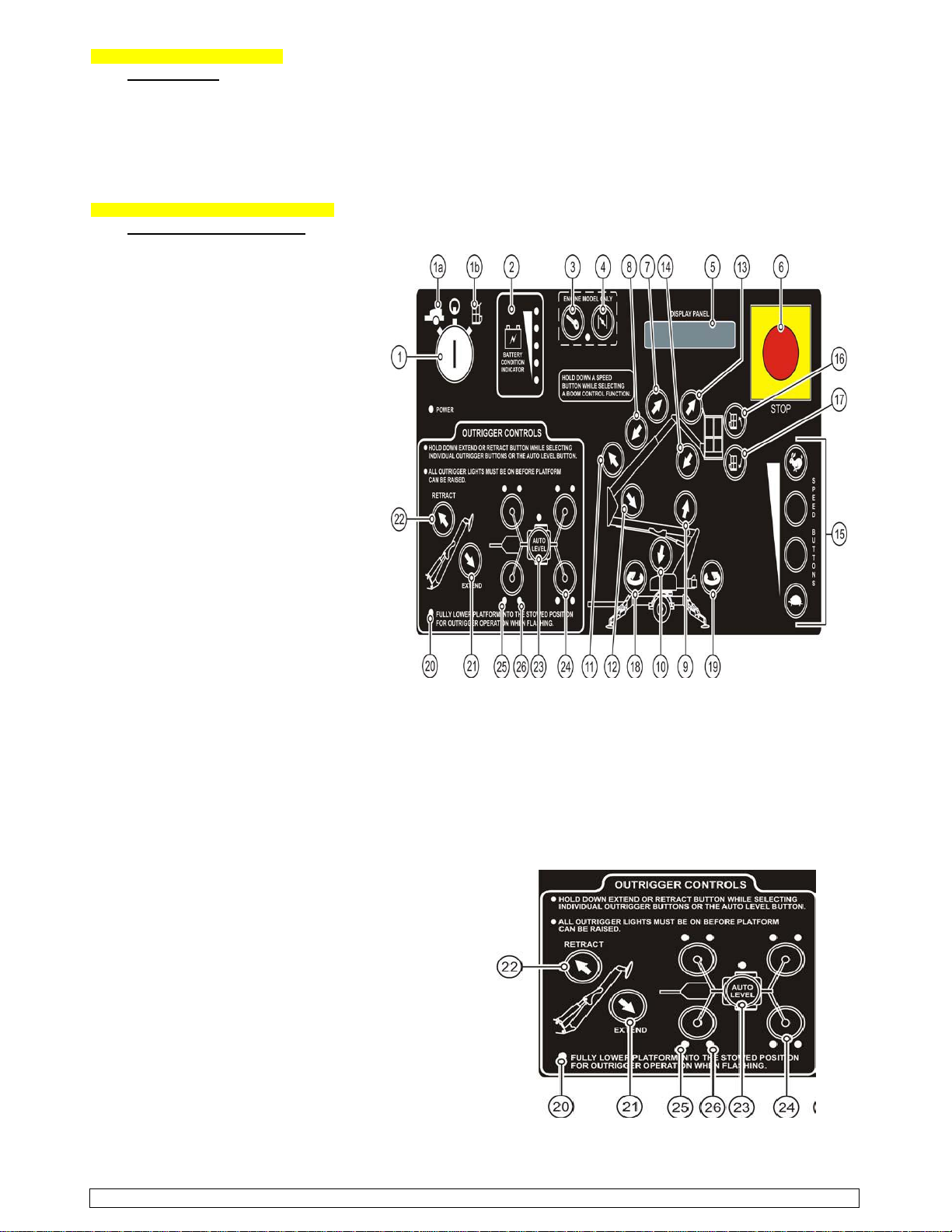
GROUND CONTROL STATION; (Figure; 3-1) Ground Control Station
(for further information, see the Manufacturer’s
“Operator’s Manual”, pages; 14-15).
The “Ground Control Station” is used to
operate outriggers and control boom
motion. To access the ground Control
Station, open the control panel access
cover found on the turnable. Turn the
key switch to the Ground Control Setting.
1. KEY SWITCH; Turning the key switch
to the PLATFORM (1a) icon selects
operation from the platform. Turning
the key switch to the GROUND (1b)
icon selects operation from the ground
Control panel. The center (power off)
position interrupts all electric and
hydraulic power operations except
emergency lowering. Remove the
key protects against unauthorized
persons. The key may be removed
with the key switch in any selected
position.
2. BATTERY CONDITION INDICATOR;
Indicator LEDs light up to indicate the
level charge remaining in the batteries.
A lighted green LED indicates an
adequate charge level. Lighted yellow
LEDs indicate the need for charging
soon. A lighted red LEDs warns the
battery charge is low; boom operations
should be halted until the batteries are recharged.
3 - 4. ENGINE START and CHOKE; does not apply to this model unit.
5. DISPLAY PANEL; The display panel is a lighted text window that displays the present operating status or an
existing error condition when the key switch is on.
6. EMERGENCY STOP BUTTON; When pushed in, the emergency STOP button disconnects electrical power to
the “Ground” and “Platform” control stations.
7 - 8. BOOM EXTEND/RETRACT BUTTONS; Pressing and holding a desired SPEED button and the BOOM EXTEND
button at the same time extends the telescopic boom. Pressing and holding a desired SPEED button and the
BOOM RETRACT button at the same time retract the boom. Boom motion continues until the buttons are
released or until the boom reaches a hard stop or
a safe travel limit.
9 - 14. BOOM RAISE/DOWN BUTTONS; Pressing and
holding a desired SPEED button and the UPPER/LOWER
/ JIB BOOM RAISE button at the same time will raise the
chosen boom. Pressing a desired SPEED button and
the UPPER/LOWER / JIB BOOM DOWN button at the
same time will lower the chosen boom. Boom motion
continues until the buttons are released or until the
boom reaches a hard stop or a safe travel limit.
15. SPEED BUTTONS; The SPEED buttons along the lower
right side of the control panel must be pressed and held
while selecting a boom function. Four speeds are
available to control positioning of the boom lift.
16 - 17. PLATFORM TILT BUTTONS; Press and hold and
hold any SPEED button and the desired PLATFORM TILT
button at the same time to level the work platform
(levels the platform only, not the boom lift).
2015 - BIL-JAX #4725A, “TOWABLE - ARTICULATE BOOM LIFT”- OPERATIONAL & SAFETY INFO…page 5 - 12
G. CONTROLS and THEIR FUNCTIONS;
GROUND CONTROL STATION; continued …
18 - 19. BOOM ROTATION BUTTONS; Pressing
and holding a desired SPEED button and the
BOOM ROTATIONCLOCKWISE or
COUNTERCLOCKWISE button at the same
time enables the boom to rotate in the direction
selected. The boom will rotate through 700
degrees until the buttons are released or
the stop is reached.
20 - 24. OUTRIGGER CONTROLS; (Figure; 3-3)
For automatic outrigger extension / retraction;
Select EXTEND or RETRACT outrigger button
and the AUTO LEVEL button at the same time.
To manually extend or retract the outriggers:
Select EXTEND or RETRACT outrigger button
and one of the OUTRIGGER buttons at the
same time. The outrigger indicator LEDs light
up when the outriggers are properly deployed
and the boom weight is on the outriggers. Each of the outer outrigger LEDs indicates load is on the
outrigger footpad. Each of the inner outrigger LED light up and a buzzer sounds when the boom is level.
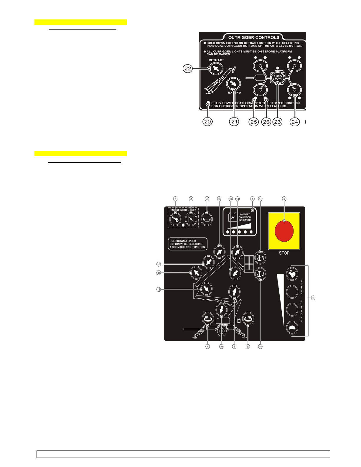
G. CONTROLS and THEIR FUNCTIONS;
PLATFORM CONTROL STATION;
(see the Manufacturer’s “Operator’s Manual”, pages; 16-17).
The “Platform Control Station” is used
to control boom motion. To access the
Platform Control Station, turn the key (Figure; 3-2) Platform Control Station
switch at the ground control station to
the platform control setting and enter
the work cage.
1 - 2. ENGINE START and CHOKE; Not
applicable on this model.
3. HORN BUTTON; Pressing the button
will sound the horn. Use HORN button
to warn personnel in the area of a
falling object hazard, impending boom
motion or the need for assistance.
4. BATTERY CONDITION INDICATOR;
Indicator LEDs light up to indicate the
level of charge remaining in the
batteries… green - good charge level,
yellow - need for charge and red -
charge level is low; boom operations
should be halted until batteries are
recharged.
5. EMERGENCY STOP BUTTON; When
pushed in, the emergency STOP button
disconnects electrical power to the
“Ground” and “Platform” control stations.
The emergency STOP pushbutton should
only be pressed to immediately stop all
boom motions. To resume control, pull
out the emergency STOP button.
6. SPEED BUTTONS; The SPEED buttons
along the lower right side of the control
panel must be pressed and held while
selecting boom functions. Four speeds are available to control positioning of the boom lift.
7 - 8. BOOM EXTEND/RETRACT BUTTONS; Pressing and holding a desired SPEED button and the BOOM EXTEND
button at the same time extends the telescopic boom. Pressing and holding a desired SPEED button and the
BOOM RETRACT button at the same time retract the boom. Boom motion continues until the buttons are
released or until the boom reaches a hard stop or a safe travel limit.
9 - 14. BOOM RAISE/DOWN BUTTONS; Pressing and holding a desired SPEED button and the UPPER/LOWER / JIB
BOOM RAISE button at the same time will raise the chosen boom. Pressing a desired SPEED button and the
UPPER/LOWER / JIB BOOM DOWN button at the same time will lower the chosen boom. Boom motion continues
until the buttons are released or until the boom reaches a hard stop or a safe travel limit.
15. SPEED BUTTONS; The SPEED buttons along the lower right side of the control panel must be pressed and
held while selecting a boom function. Four speeds are available to control positioning of the boom lift.
2015 - BIL-JAX #4725A, “TOWABLE - ARTICULATE BOOM LIFT”- OPERATIONAL & SAFETY INFO…page 6 - 12

G. CONTROLS and THEIR FUNCTIONS;
PLATFORM CONTROL STATION;
16 - 17. PLATFORM TILT BUTTONS; Press and hold and hold any SPEED button and the desired PLATFORM TILT
button at the same time to level the work platform (levels the platform only, not the boom lift).
NOTE; There is a power outlet located in the boom lift platform area. It is provided for running
electrical power tools from the work platform. A connecting power cord must be plugged into a
suitable power source. The power plug is located on the trailer frame, in the front of the
accessory equipment stowage plate. The outlet is rated for a 15-ampere load. Do not overload
the accessory power circuit.
H. OPERATION INSTRUCTIONS;
NORMAL OPERATING PROCEDURES; (for further information, see Manufacturer’s “Operator Manual”,
pages; 18-19)
1. Read and follow all safety precautions and operating instructions, as well as all applicable government
regulations.
2. Conduct a “Pre-Operation Inspection”
(Refer to E. USAGE RESPONSIBILITIES - above, Also refer to the Manufacturers “Operator Manual”, section
4, under Daily Service Checks, pages; 26-27 for more information).
3. Position the boom lift at the work area. Make sure the boom lift is on a firm and level surface and there
are no potential hazards. (as describe in section “F.” USAGE RESPONSIBILITIES - Work Safety, above).
4. Apply the parking brake or chock the wheels
5. Lower the tongue jack and unhitch the boom lift from the tow vehicle.
WARNING; Unhitch the boom lift from the tow vehicle prior to operating. Failing to unhitch the
boom lift, can lead to the boom lift becoming unstable which can lead to personnel injury or
death. It can also do damage to the equipment and / or the tow vehicle.
6. Turn the key switch on Ground Control Station to operate ground controls. If power does not come on,
make sure both emergency STOP buttons (ground and platform) are pulled out and the main power
disconnect is plugged in.
7. The control microprocessor will perform self-diagnostic to test the operating system. After several seconds,
the DISPLAY PANEL window will read;
BIL-JAX
A STEP ABOVE
8. Verify that the control status indicator LED is lit. If the control status indicator LED is not lit or is flashing,
the outriggers buttons will not work. A flashing control status LED indicates that one or more of the
booms is raised and needs to be stowed. (refer to Figure 3-1 and Figure 3-3)
9. Extend the outriggers manually or using the AUTO LEVEL button. When the boom is leveled properly, a
buzzer will sound and two LEDs at each OUTRIGGER button and the LED at the AUTO LEVEL button will
be lit.
AUTO LEVEL; Press and hold the EXTEND and AUTO LEVEL buttons at the same time.
MANUAL LEVEL; Extend the two outriggers closest to the trailer coupler first. Lower each pair of
outriggers by pressing the EXTEND button
10. Verify that the auto level indicator LED is lit. If the auto level
indicator is not lit, the boom may not be level.
11. Pull the latch release on the boom travel latches, raise the
latch handle and swing the latch U-bolt down.
12. Verify that the platform is properly attached to the mounting
bracket on the boom end. The “Retaining Pin” should be fully
inserted through the platform and the mounting bracket on
the boom end.
WARNING; Failure to verify proper attachment of the
platform to the boom end could cause the platform to
separate from the boom, resulting in serious injury or
death to the operator.
13. Use the ground control panel to operate the boom lift functions. Raise, lower, extend and rotate the boom
by pressing and holding the desired SPEED and function buttons at the same time. Become familiar with
the location and function of all controls. Learn to smoothly start and stop all boom motions.
14. Fully lower the boom onto the boom rest to position the platform for boarding. Turn the key switch to the
platform control position.
15. Raise the safety bar and enter the work platform. Put on the safety harness and attach the lanyard to
the “Fall Protection Attachment Point” on the side of the platform support beam.
16. Become familiar with the location of all controls. Use the platform control panel to operate the boom lift
functions. Raise, lower, extend and rotate the boom by pressing the desired SPEED and function buttons
at the same time. Learn to smoothly start and stop all boom motions.
17. Should the platform become tilted out of the normal vertical axis, press and hold the desired SPEED
button and one of the PLATFORM TILT buttons at the same time to adjust.
18. Monitor the Battery Condition Indicator during operation and charge the batteries as necessary.
2015 -BIL-JAX #4725A, “TOWABLE - ARTICULATE BOOM LIFT”- OPERATIONAL & SAFETY INFO…page 7 - 12

H. OPERATION INSTRUCTIONS;
NORMAL OPERATING PROCEDURES; continued …
19. Always fully retract, rotate and lower the boom to the stowed position before exiting the platform.
20. When all boom lift operations are completed, fully retract the telescoping boom extension. Center boom
over the boom rest and fully lower boom until seated in the stowed position for transport. Safety switches
prevent the outrigger retraction until boom is completely lowered and stowed for transport.
21. Unfasten the safety harness and exit the platform.
22. Turn the key switch to the ground controls position.
23. Inspect the area beneath lift and trailer for obstructions before retracting outriggers. Press and hold the
outriggers RETRACT button and the AUTO LEVEL button until all outriggers are fully retracted to their
upright position.
24. Turn the key switch to the OFF position and remove the key.
MANUAL BOOM OPERATION; (for further information, see the Manufacturer’s Operation Manual, pages; 20-21)
Manual retraction, rotation and lowering and lowering functions allow the Telescoping Boom Lift to be moved
and lowered during hydraulic power interruption or failure. In each instance, refer to Figure 3-5. The following
procedures for manual retraction, rotation and lowering a person on the ground to operate the manual controls
and hand pump. The hydraulic hand pump is located in the pump compartment. In case of a power failure the
hand pump and selected hydraulic valve settings can be used to manually retract the “Telescoping Boom” or
rotate the boom turnable. To begin manual retraction or rotation, turn Proportional Valve counterclockwise
until it stops and insert pump handle into the pump handle fitting.
MANUAL RETRACTION; Pushing and holding the Retract button while simultaneously actuating Hand Pump
will Retract the extension boom section.
MANUAL ROTATION; To rotate the Turnable …
Clockwise; Push and hold the Rotation button and simultaneously actuate Hand Pump.
Counterclockwise; Pull the Rotation button out and simultaneously actuate Hand Pump.
NOTE; Return proportional valve to its original position before lowering the lift or
resuming normal operations.
Figure; 3-5 Hand Pump and Controls for Manual Lift Operation.
MANUAL LOWERING;
(see the Manufacturer’s “Operator Manual”, page; 21).
Each Manual Lowering Valve is equipped with a
plunger, found at the base lift cylinder. Use the
plunger to lower the platform in case of a complete
electrical power failure, a load shift or other
emergency. To lower the work platform, pull the
valve plunger forward. Continue pulling the plunger
to completely lower the boom.
2015 -BIL-JAX #4725A, “TOWABLE - ARTICULATE BOOM LIFT”- OPERATIONAL & SAFETY INFO… page 8 - 12
WARNING; There are very few occasions
where this maneuver would be used. “Do Not
Attempt” this without direct TRC involvement
and approval.

I. RECHARGING LIFT BATTERIES;
(for further information, see the Manufacturer’s “Operator’s Manual”, page; 22).
Recharge the “Boom Lift” batteries after each 8-hour work shift or as needed. When the “Boom Lift” is not in
use, batteries should be recharged at least once per week. Under normal circumstances, battery recharge
should take approximately 10-12 hours. However, a full recharge may take up to 24-hours, if the battery
charge is extremely low.
NOTE; TRC ask that the batteries be recharged overnight (when possible) before returning
the next morning. This will help us with our scheduling and allow quick turnaround to the next
customer.
WARNING; Recharge batteries in a well-ventilated area only. Do not charge batteries near
fire, spark or other potential ignition sources. Batteries may emit highly explosive hydrogen
gas while charging. Failure to properly ventilate the charge gases may result in serious injury
or death. Always charge “Boom Lift” batteries away from flammable materials.
To recharge the “Boom Lift” batteries as follows;
1. Move the boom lift to a “well-ventilated” area with direct access to a grounded 120 VAC electrical
outlet. Keep the boom and batteries away from open flames or other ignition sources.
2. Attach a 12 AWG (outdoor-rated) multi-strand, ground (3-prong) (figure; 3-7)
extension cord with a length no longer than 20’. Plug it into the Battery Charger Faceplate
cord with a length no longer than 20’. Plug it into the receptacle
located on the cargo plate in front of the turnable.
WARNING; Using an underrated or longer power cord will
reduce the output of the battery charger and may extend
the charge time or worse do damage to the battery
charger.
3. Plug the extension cord into the outlet. Verify that the green
CHARGING indicator LED is lit on the battery charger faceplate
(figure 3-7).
4. The Charging indicator LED remains lit continuously during the
first stage of the charge cycle. The bulk mode CHARGE CURRENT
will be displayed on the battery charger faceplate.
5. Press and hold the BATTERY VOLTAGE button to display the
detected battery voltage.
6. If a battery fault is detected, the appropriate fault code will appear on the CHARGE CURRENT display.
The red CHECK BATTERY indicator LED will become lit.
(sub to Table 4-1 for battery fault codes)
WARNING; Do not disconnect any output leads or connectors between the batteries and the charger
when the charger is on. To stop a charge in progress, always unplug the extension cord from the AC
power source.
7. When the battery charge reaches 80% of capacity, the yellow 80% CHARGED indicator LED will become lit
and the green CHARGING indicator LED will begin to flash.
8. When the batteries have reached a full charge, the green and yellow indicators LEDs will turn themselves off.
CC (Charge Complete) will appear on the CHARGE CURRENT display. After two hours, this display will fade
and the CHARGE CURRENT will read 00.
9. Unplug the extension cord from the outlet and charger receptacle on the boom lift.
CAUTION; Always unplug the battery charger power cord before moving the boom lift. Failure to
disconnect power cord will cause damage to the equipment.
2015 -BIL-JAX #4725A, “TOWABLE - ARTICULATE BOOM LIFT”- OPERATIONAL & SAFETY INFO…page 9 - 12

J. BOOM LIFT TRANSPORT - ROAD TRAVEL;
The boom lift trailer is a single axle trailer fitted with a two-inch ball hitch, surge brakes, breakaway safety cable,
safety chains, brake lights and side marker lights. Proper boom lift transport requires the correct hookup and
inspection of these trailer components before towing. Use the following procedure to hitch, tow and back the boom
lift trailer. When backing up, avoid sharp turns to keep from jackknifing the trailer and doing damage to the trailer
tongue, coupling and frame.
CAUTION; Obtain, read and obey all recommendations set forth by the tow vehicle manufacturer
before attempting to transport equipment. Verify that equipment weight does not exceed the vehicle’s
towing capacity. Exceeding the tow vehicle’s rated capacity may result in damage to tow vehicle,
boom lift and create a dangerous situation.
TRAILER HITCHING;
(For better understanding, please look in the Manufacturer’s
“Operating & Safety” Manual, this is a more detail illustration,
than figure; 3-8 on page 23).
1. Back the tow vehicle to the trailer. Verify that he ball
and hitch are in line and that the trailer hitch will clear
the ball. Jack up the tongue as needed.
2. Align the ball and hitch. Wrap and fasten the break-
away safety cable around the ball hitch.
3. Hold ball hitch release lever open and lower hitch
onto the ball. Let go of the release lever to secure the
ball.
4. Crank the jack down to check for secure coupling. If
jacking will raise the tow vehicle bumper two or three
inches, the ball hitch coupling is secure.
5. Pull the pin keeper and pivot locking pin, raise the jack
to the travel position and reinstall the pivot locking pin
and pin keeper.
CAUTION; Always cross and attach the safety chains before towing. Failure to attach safety chains
properly will allow tongue to drop in case of ball hitch failure, resulting in serious damage to the trailer
and equipment.
6. Attach the trailer safety chains to the tow vehicle. Make sure the chains cross under the trailer tongue. If
needed, cross the chains over then under the tow bar to prevent dragging.
7. Connect the trailer lights to the tow vehicle power plug
8. Check the position of the breakaway safety cable indicator block. If the indicator block is not in the brakes-
released position, the brakes may drag.
TOWING; We ask that you refer to the Manufacturer’s “Operator’s Manual”, (page; 23) for instructions when preparing
to tow the boom lift. The Lift should be prepared for road travel (see page 18). Place the loader boom and
outriggers in the transport position and the boom in the transport lock position. Approach intersections with caution,
observe speed and traffic control signs. Don’t speed. Know your stopping distance at a given speed. Avoid panic
stops and sharp turns. If travel backs up, pull over and allow other vehicles to pass. Avoid traveling on any surfaces
that adversely affect vehicle stability. The driver should be alert and aware of potential hazards when traveling. The
driver should also make use of their headlights and flashers when towing the boom lift. Try to avoid peak traffic time
movement; 7-8 am, 12-1 pm and 5-6 pm. Do not travel during “low visibility” hours and times; early morning, dust
dark, fog, rain, smoke, etc.) or at night. Use great care when turning, always use hand signals and turn signals.
K. MACHINE CHARGES & TIME OUT PERIODS;
TRC “rate charges” and “time out definitions” for this equipment …
MINIMUM; 4-hours from the time you rent the item till the time you return it. This is only available during week days.
No overnights are available on the minimum rate charge.
DAILY;(1-day charge) 24-hours, during weekday period.
WEEKENDS; (1-day charge) Saturday pickup; (between 7:00 -11:00 am) return Monday; (7:00 - 8:30 am) morning.
WEEK RATES; (3-day charge) 7-days out, return the equipment at the time you picked it up but exactly a week later.
MONTH RATE; (7-day charge) 4-weeks out, return the equipment at the time you picked it up but exactly 4-weeks
later. If you see you are going to be using the equipment longer than your “schedule rental period”, please contact us!
L. YOUR COMMENTS;
We feel that it is important to have customer input and feedback. Please feel free to make any comments on these
instructions, our equipment, our service or any other aspects of our business. Your comments will be appreciated.
N. FOR YOUR CONVIENCE;
We have; aerators, aerial lifts, air blowers, air scrubbers, backhoes, breakers, carpet blowers, carpet & upholstery .
cleaners; (cold & hot water types) compaction, concrete & masonry equipment, conduit benders, demolition & hammer .
drills, dehumidifiers, detectors; (magnetic & metal), excavators, fish tapes (pullers), forklifts; (hard surface & rough .
terrain), generators, heaters, jacks, lawn rollers; (18” & 24”), levels; (construction & transits), rods, targets, & tripods, .
lights; (stands & towers), pipe; (cutters, cutting oil, stands, thatchers, threaders; (electric & manual), threading dies; .
(1/8”, 1/4”, 3/8”, 1/2”, 3/4”, 1”, 1 1/4”, 1 3/8”, 1 1/2” & 2”) & tripod vises, wrenches; (pipe / straight; 24”, 36” & 48”), .
pressure washers; (cold & hot water), power & manual tree pole saws, pumps; (centrifugal, diaphragm, submersibles & .
trash - various sizes), saws; (band, chop, concrete chainsaws, demolition,miter, reciprocating & walk-behind), signs; .
(wet floor), squeegee (floor), traffic control items; barricades, barrel drum, traffic cones, etc., trenchers; (walk-behind & .
2015 -BIL-JAX #4725A, “TOWABLE - ARTICULATE BOOM LIFT”- OPERATIONAL & SAFETY INFO…page 10 - 12

N. FOR YOUR CONVIENCE; continued …
items; boots (rubber), dust mask, respirators, ear plugs, gloves, hard hats, safety glasses / goggles, rain suits;(3-pc & .
trench coat styles), reflective safety vest. We have mesh safety fencing & vinyl tape; (crowd control; (caution & danger; .
300’ & 1,000’ rolls, surveyor’s) and “much” more! “It’s all in store for you” at TAYLOR RENTAL CENTER ! .
-----------------------------------------------------------------------------------------------------------------------------------------------------------------
Barricades; -------------------------------------------------------------- Traffic; ------------------------------------------------------------------------------------------------------
Drum Folding, Type II Safety Fencing; Cones Flagging Hand Paddles Pennants Tape - 3” Vinyl; Caution
w/wo flashing lights hi-dense & economy Reflective OSHA perimeter Danger & Wet Paint
4’ x 50’ 28” height 106’ 300’ & 1,000’ rolls
Personnel Safety Items; --------------------------------------------------------------------------------------------------------------------------------------------------------------------
Dust Ear Glasses & Goggles Face Boots Gloves Canvas Hard Kneepads Safety Vest; Aerial
Mask Plugs Clear & Tinted Shield Hats Hats Plain & Reflective Styles Harnesses
Compaction & Prep Equipment; --------------------------------------------------------------- Demolition & Earth Moving Equipment; -------------------------------
Asphalt Reversible Uprights Riding Paint Surveyor’s Levels & 1,100 Lb. Drop Breaker Trenchers - Riding & Walk-Behind
Dirt Plates Plates Rollers Markers Tape Transits with Tow Trailer Units with Tow Trailers
Demolition & Earth Moving Equipment; -------------------------------------------------------------------------------------------------------------------------------------------------
185 CFM Air Pneumatic & Electric Breakers Backhoe - Case 580N (4-WD) Extend-A-Hoe Excavators - Bobcat E35
Compressors Air Hoses & Bits
Concrete Saws;
Handheld, Walk-Behind
& Chain Saw Style
Demolition & Earth Moving Equipment; ----------------------------------------------------------------------------------------------------------------------------------------------
Front-End Loaders - Case SR200 & TLB - Kubota L-45
Accessory Items; Augers, Beakers & Pallet Forks Tractor, Loader, Backhoe
Tree Pole Saws Weed Eaters
Chain Saws
Lawn & Garden Equipment; ---------------------------------------------------------------------------
Brush Chippers Log Splitters Sod Cutters Stump Grinders
1560 Highway 1 South / MLK Blvd.
(1 ½ Blocks North of the Greenville Mall)
Greenville, Mississippi 38701
(662) 335-3535 / Fax; 335-3533
Monday thru Friday 7:00 am - 5:30 pm
Saturday; 7:00 am - 11:00 am
e-mail; [email protected]
Towable - Articulate Boom Lift web; taylorrentalgreenville.com
(45’ max foot height / 51’ max working height ) ---- ”Serving the Greater Delta Area since 1979” ----
01/01/15 2015 -BIL-JAX #4725A, “TOWABLE - ARTICULATE BOOM LIFT”- OPERATIONAL & SAFETY INFO…page 11 - 12


Towable - Articulate “Boom” Lift ...
I have read or will read TRC’s “twelve pages” of operational and
safety information on this “Towable - Articulate “Boom” Lift” and I fully
understand or will understand this printed material as well as any verbal
instructions, before attempting to use or operate this equipment! I
further understand that TRC “strongly encourages”me to review the
complete Manufacturer’s “Operation and Safety” Manual, located on
board the lift and also available online, prior to use. That the information
printed in the proceeding twelve pages only hits a few of the high
points and contains “some” useful information but the Manufacturer’s
“Operation & Safety Manual” contains the complete instructions (OS
Manual is located on the machine). For additional safety… “we suggest”
using a (ground) spotter (a TRC trained operator) to help locate, recognize
and anticipate dangers that might not be seen or acted on by the basket
operator while working above the ground.
We TRC ask that you agree to faithfully abide by these restrictions and
guidelines to help lower the chances of an accident or injury to any
“qualified” participants using this equipment! That you further agree to
be responsible for the equipment, until “it is returned” to our store
location at 1560 Highway 1 South, MLK Blvd., in Greenville, Mississippi,
and checked in during our business hours by you (the customer) or a
representative or it is “picked-up” by TRC uniformed personnel (as
specified in the rental contract agreement)!
X ____________________________________________________.
* Rental Management Magazine; September 2012, “The Fall Protection Question” pg. 18
01/01/15 2015 -BIL-JAX #4725A, “TOWABLE - ARTICULATE BOOM LIFT”- OPERATIONAL & SAFETY INFO …page 12 - 12
Table of contents
Other BilJax Boom Lift manuals


Popular Boom Lift manuals by other brands


JLG
JLG 450A Operation and safety manual

Genie
Genie GS-2669 RT Service manual

Oshkosh Corporation
Oshkosh Corporation JLG 1200SJP Operation and safety manual

Oshkosh Corporation
Oshkosh Corporation 150HAX Operation and safety manual

Haulotte Group
Haulotte Group xlb-4725a Operator's maintenance manual

Terex
Terex Genie Z-62/40 Operator's manual


