BilJax XLB-4725A User manual

Operation and
Maintenance Manual
XLB-4725A
Proportional
Hydraulic Boom Lift
XLB-4725A
B33-01-0072-01
AERIAL WORK PLATFORMS
AERIAL WORK PLATFORMSAERIAL WORK PLATFORMS
AERIAL WORK PLATFORMS

BOOM PERSONNEL LIFT
This equipment is designed and manufactured in compliance with the duties, re-
sponsibilities, and standards set forth for manufacturers in the ANSI 92.2 standard
in effect at the time of manufacture.
This equipment will meet or exceed applicable OSHA codes and ANSI A92.2 stan-
dards when used in accordance with sections 7, 8, 9 & 10 of ANSI A92.2 and all
other manufacturer’s recommendations.
It is the responsibility of the user of this equipment to follow all applicable ANSI,
OSHA, Federal, State, and local codes and regulations that govern the safe opera-
tion of this equipment.

i
Table of Contents
1
11
1Safety ............................................................................................................... 1-1
1-1 Introduction........................................................................................ 1-1
1-2 Before Operation............................................................................... 1-3
1-3 During Operation............................................................................... 1-4
1-4 Maintenance Safety........................................................................... 1-6
1-5 Damaged Equipment Policy............................................................. 1-7
2
22
2Introduction .................................................................................................... 2-1
2-1 General Description........................................................................... 2-1
2-2 Specifications..................................................................................... 2-2
2-3 Warranty............................................................................................. 2-2
3
33
3Operation ........................................................................................................ 3-1
3-1 Operator Controls.............................................................................. 3-1
3-2 Normal Operating Procedure............................................................ 3-6
3-3 Emergency Lowering......................................................................... 3-7
3-4 Manual Boom Rotation .................................................................... 3-7
3-5 Battery Recharge (DC Model Only)............................................... 3-8
3-6 Boom Lift Transport....................................................................... 3-10
4
44
4Maintenance.................................................................................................... 4-1
4-1 Scheduled Service Checks................................................................ 4-1
4-2 Wheel Nut Torque Requirements.................................................... 4-3
4-3 Lubrication......................................................................................... 4-3
4-4 Hydraulic System .............................................................................. 4-6
4-5 Leveling System.............................................................................. 4-11
4-6 Troubleshooting ............................................................................... 4-14
4-7 Material Safety Data Sheets .......................................................... 4-23
5
55
5Replacement Decals........................................................................................ 5-1
6
66
6Parts List ......................................................................................................... 6-1
6-1 Upper Boom Parts List.................................................................... 6-2
6-2 Lower Boom Parts List.................................................................... 6-4
6-3 Upper Cylinder Parts List................................................................ 6-6
6-4 Lower Cylinder Parts List................................................................ 6-8
6-5 DC Model Battery Compartment Parts List.................................... 6-10
6-6 Gas Model Engine Compartment Parts List....................................... 6-14
6-7 DC Model Power Compartment Parts List.................................. 6-18
6-8 Gas Model Power Compartment Parts List ....................................... 6-22
6-9 Frame and Rotation Unit List....................................................... 6-26
6-10 Hitch and Jack Assembly Parts List ............................................ 6-28
6-11 Square Tube Axle and Wheel Assembly Parts List................... 6-32
6-12 Hex Tube Axle and Wheel Assembly Parts List........................ 6-34
6-13 Tail Lights and Junction Box Parts List ..................................... 6-36
6-14 Front Outriggers Parts List............................................................ 6-38
6-15 Rear Outrigger Parts List............................................................... 6-40
6-16 Basket Parts List............................................................................. 6-42
6-16A Basket Parts List, Early Model..................................................... 6-46
6-17 Upper Control Box – External Parts List...................................... 6-50
6-18 Upper Control Box – Internal Parts List....................................... 6-51
6-19 Lower Control Box Parts List....................................................... 6-52
6-20 Proportional Valve Assembly Parts List....................................... 6-54
6-21 Surge Brakes Parts List ................................................................. 6-55
6-22 DC Model Hydraulic System Parts List ...................................... 6-56
6-23 Gas Model Hydraulic System Parts List...................................... 6-58
7
77
7ANSI Reprint ................................................................................................. 7-1

ii
List of Illustrations
Figure 3-1. Battery ON/OFF Switch..........................................................................3-1
Figure 3-2. Lower Control Panel...............................................................................3-2
Figure 3-3. Upper Control Panel...............................................................................3-4
Figure 3-4. Emergency Lowering Valve....................................................................3-7
Figure 3-5. Boom Rotation........................................................................................3-7
Figure 3-6. Battery Charger and Receptacle..............................................................3-8
Figure 3-7. Battery Charger.......................................................................................3-9
Figure 3-8. Breakaway Safety Cable .......................................................................3-10
Figure 3-9. Jack Travel Position..............................................................................3-10
Figure 3-10. Trailer Hitching Checkpoints................................................................3-11
Figure 3-11. Backup Lever Position..........................................................................3-12
Figure 4-1. Wheel Nut Tightening Sequence.............................................................4-3
Figure 4-2. Lubricate Monthly...................................................................................4-3
Figure 4-3. Lubricate Semi-Annually........................................................................4-4
Figure 4-4. Lubrication of Dexter Axles....................................................................4-5
Figure 4-5. Hydraulic Cylinder Removal ..................................................................4-7
Figure 4-6. Hydraulic Cylinder Repair......................................................................4-9
Figure 4-7. Checking Outrigger Bushings...............................................................4-11
Figure 4-8. Outrigger Bushing Replacement...........................................................4-12
Figure 4-9. Adjusting Axle Position Switches.........................................................4-13
Figure 4-10. Lower Controller Board........................................................................4-16
Figure 4-11. Level Sensor .........................................................................................4-18
Figure 4-12. DC Model Hydraulic Diagram..............................................................4-19
Figure 4-13. Gas Model Hydraulic Diagram.............................................................4-20
Figure 4-14. PC Logic Diagram, DC Model..............................................................4-21
Figure 4-15. PC Logic Diagram, Gas Model.............................................................4-22
Figure 5-1. Replacement Decals, Sheet 1 of 3...........................................................5-2
Figure 5-1. Replacement Decals, Sheet 2 of 3...........................................................5-3
Figure 5-1. Replacement Decals, Sheet 3 of 3...........................................................5-4
Figure 5-2. Decal Locations, Trailer and Boom........................................................5-5
Figure 5-3. Decal Locations, Power Compartments Exterior....................................5-6
Figure 5-4. Decal Locations, Power Compartment Interior.......................................5-6
Figure 6-1. Upper Boom............................................................................................6-2
Figure 6-2. Lower Boom...........................................................................................6-4
Figure 6-3. Upper Cylinder .......................................................................................6-6
Figure 6-4. Lower Cylinder.......................................................................................6-8
Figure 6-5. DC Model Battery Compartment..........................................................6-10
Figure 6-6. Gas Model Engine Compartment..........................................................6-14
Figure 6-7. DC Model Power Compartment............................................................6-18
Figure 6-8. Gas Model Power Compartment...........................................................6-22
Figure 6-9. Frame and Rotation Unit.......................................................................6-26
Figure 6-10. Hitch and Jack Assembly......................................................................6-28
Figure 6-11. Square Tube Axle and Wheel Assembly...............................................6-32
Figure 6-12. Hex Tube Axle and Wheel Assembly...................................................6-34
Figure 6-13. Tail Lights and Junction Box................................................................6-36
Figure 6-14. Front Outriggers....................................................................................6-38
Figure 6-15. Rear Outrigger ......................................................................................6-40
Figure 6-16. Basket ...................................................................................................6-42
Figure 6-16A. Basket, Early Model..............................................................................6-46
Figure 6-17. Upper Control Box (DC Model) – External..........................................6-50
Figure 6-18. Upper Control Box (DC Model) – Internal...........................................6-51
Figure 6-19. Lower Control Box (Gas Model)..........................................................6-52
Figure 6-20. Proportional Valve Assembly...............................................................6-54
Figure 6-21. Surge Brakes.........................................................................................6-55
Figure 6-22. DC Model Hydraulic System................................................................6-56
Figure 6-23. Gas Model Hydraulic System ...............................................................6-58

iii
List of Tables
Table 1-1. Minimum Safe Approach Distances....................................................... 1-4
Table 2-1. Specifications.......................................................................................... 2-2
Table 4-1. Daily/Weekly Service Checks ................................................................ 4-1
Table 4-2. Monthly Service Checks......................................................................... 4-2
Table 4-3. Troubleshooting Chart.......................................................................... 4-14
Table 4-4. Error Codes........................................................................................... 4-15
Table 4-5. LED Indicators ..................................................................................... 4-17
Table 4-6. Upper Control Box Specifications........................................................ 4-17
Table 4-7. Level Sensor LEDs............................................................................... 4-18
Table 5-1. Replacement Decals, DC Model............................................................. 5-1
Table 6-1. Upper Boom Parts List........................................................................... 6-3
Table 6-2. Lower Boom Parts List........................................................................... 6-5
Table 6-3. Upper Cylinder Parts List....................................................................... 6-7
Table 6-4. Lower Cylinder Parts List....................................................................... 6-9
Table 6-5. DC Model Battery Compartment Parts List.......................................... 6-11
Table 6-6. Gas Model Engine Compartment Parts List.......................................... 6-15
Table 6-7. DC Model Power Compartment Parts List........................................... 6-19
Table 6-8. Gas Model Power Compartment Parts List........................................... 6-23
Table 6-9. Frame and Rotation Unit Parts List ...................................................... 6-27
Table 6-10. Hitch and Jack Assembly Parts List...................................................... 6-29
Table 6-11. Square Tube Axle and Wheel Assembly Parts List .............................. 6-33
Table 6-12. Hex Tube Axle and Wheel Assembly Parts List................................... 6-35
Table 6-13. Tail Lights and Junction Box Parts List................................................ 6-37
Table 6-14. Front Outriggers Parts List ................................................................... 6-39
Table 6-15. Rear Outrigger Parts List...................................................................... 6-41
Table 6-16. Basket Parts List................................................................................... 6-43
Table 6-16A. Basket Parts List, Early Model............................................................. 6-46
Table 6-17. Upper Control Box – External Parts List.............................................. 6-50
Table 6-18. Upper Control Box – Internal Parts List............................................... 6-51
Table 6-19. Lower Control Box Parts List............................................................... 6-53
Table 6-20. Proportional Valve Assembly Parts List............................................... 6-54
Table 6-21. Surge Brakes Parts List......................................................................... 6-55
Table 6-22. DC Model Hydraulic System Parts List................................................ 6-57
Table 6-23. Gas Model Hydraulic System Parts List.............................................. 6-59
Table 7-1. Minimum Safe Approach Distance (M.S.A.D.) to energized
(exposed or insulated) power lines and parts.......................................... 7-7

iv

1-1
1
11
1
Safety
1-1 INTRODUCTION
Familiarity and proper training are required for the safe operation of mechanical equip-
ment. Equipment operated improperly or by untrained personnel can be dangerous. Read
the operating instructions in this manual and become familiar with the location and proper
use of all controls. Inexperienced operators should receive instruction from someone fa-
miliar with the equipment before being allowed to operate the machine. The use of intelli-
gence and common sense in the operation of mechanical equipment is the best practice in
any safety policy. Be professional and always observe the safety procedures set forth in
this manual.
All OSHA, ANSI, state, and local codes and regulations pertaining to this equipment
should be obtained, read, and thoroughly understood before attempting to operate this
equipment. Persons under the influence of drugs, alcohol, or prescription medication
should not be on or near this equipment. Common sense should be implemented at all
times during the use of this equipment. Do not operate this equipment in areas where the
equipment or user may come in contact with a live power source.
The information contained herein is not to be considered as legal advice and is intended
for informational purposes only. This information is offered to alert Bil-Jax customers to
procedures that may be of concern to them.
This information is not intended to be all inclusive and is to be followed in the use of
Bil-Jax equipment only.
For any questions concerning the safe use of this equipment, call 419.445.9675 before
operating.
XLB-4725A
1-2
Safety Notes
This manual contains DANGERS, WARNINGS, CAUTIONS, and NOTES that must be
followed to prevent the possibility of improper service, damage to the equipment, or per-
sonal injury.
DANGER
Dangers warn of equipment operation near electrical power lines that could lead
to personal injury or death.
WARNING
Warnings describe conditions or practices that could lead to personal injury or
death.
CAUTION
Cautions provide information important to prevent errors that could damage ma-
chine or components.
NOTE: Notes contain additional information important to a procedure.

1 — SAFETY
1-3
1-2 BEFORE OPERATION
Ensure the following general safety precautions are followed before operating the
XLB-4725A Boom Lift.
•ALWAYS survey the usage area for potential hazards such as untamped earth
fills, unlevel surfaces, overhead obstructions, and electrically charged conductors
or wires. Be aware of any potential hazards and always consider what could hap-
pen. Watch for moving vehicles in the operating area.
•ALWAYS read, understand, and follow the procedures in this manual before at-
tempting to operate equipment.
•ALWAYS inspect the equipment for damaged or worn parts. Check for cracked
welds, hydraulic leaks, damaged wiring, loose wire connectors, damaged outrig-
gers, low tire pressure, uneven tire wear, or tire damage. Also check for any im-
proper operation. NEVER operate equipment if damaged in any way. Improperly
operating equipment must be repaired before using.
•ALWAYS wear proper clothing for the job. Wear protective equipment as re-
quired by federal, state, or local regulations. The operator MUST wear a safety
harness and lanyard.
•ALWAYS locate, read, and follow all directions and warnings displayed on the
equipment.
•ALWAYS inspect the equipment for “DO NOT USE” tags. NEVER use equip-
ment tagged in this way until all repairs are made and all “DO NOT USE” tags
are removed by authorized maintenance personnel.
•ALWAYS make sure the basket and outrigger shoes are free of mud, grease, or
other slippery material to reduce the possibility of slipping.
•NEVER allow improperly trained personnel to operate this equipment. Only
trained and authorized personnel shall be allowed to operate this equipment.
•NEVER operate this equipment if you are under the influence of alcohol or
drugs, or if you feel ill, dizzy, or unsteady in any way. Operators must be physi-
cally fit, thoroughly trained, and not easily excitable.
•NEVER modify, alter, or change the equipment in any way that would affect its
original design or operation in any way.
•NEVER operate this equipment in ways for which it is not intended.

XLB-4725A
1-4
1-3 DURING OPERATION
Ensure the following general safety precautions are followed during the operation of the
XLB-4725A Boom Lift.
DANGER
This machine is not insulated for use near electrical power lines and DOES NOT
provide protection from contact with or close proximity to any electrically charged
conductor. Operator must maintain safe clearances at all times (10 feet minimum)
and always allow for platform movement such as wind induced sway. Always con-
tact the power company before performing work near power lines. Assume every
line is hot. Remember, power lines can be blown by the wind.
Refer to Table 1-1 for minimum safe approach distances between machine and electrical
power lines.
Table 1-1. Minimum Safe Approach Distances
Minimum Safe Approach Distance
Voltage Range
(Phase to Phase) (Feet) (Meters)
0 to 300V Avoid Contact
Over 300V to 50KV 10 3.05
Over 50KV to 200KV 15 4.60
Over 200KV to 350KV 20 6.10
Over 350KV to 500KV 25 7.62
Over 500KV to 750KV 35 10.67
Over 750KV to 1000KV 45 13.72
•ALWAYS position lift far enough away from power sources to ensure that no
part of the lift can accidentally reach into an unsafe area. This includes full ex-
tension of the boom through 360 degrees rotation.
•ALWAYS operate only on a firm and level surface. NEVER use on surfaces that
do not support the equipment with its rated load capacity and the resulting force
exerted on the outriggers during boom extension and rotation.
•ALWAYS keep yourself and all personnel away from potential pinch or shear
points.
•ALWAYS report any misuse of equipment to the proper authorities. Horseplay is
prohibited.
•ALWAYS maintain good footing on the work platform. NEVER wear slippery
soled shoes.
•ALWAYS make certain all personnel are clear and there are no obstructions be-
fore repositioning basket.
•ALWAYS cordon off area around the outriggers to keep personnel and other
equipment away from it while in use.
•ALWAYS stay clear of wires, cables, and other overhead obstructions.
•ALWAYS engage the boom travel locking pin before towing the trailer.

1 — SAFETY
1-5
•NEVER allow electrode contact with any part of the basket if welding is being
performed from the platform.
•NEVER use without the outriggers fully extended, locked, and firmly based.
When on soft surfaces, ALWAYS use outrigger base plates.
•NEVER override or by-pass manufacturer's safety devices.
•NEVER attach a safety harness to an adjacent structure, pole, or equipment
while working from the boom platform.
•NEVER release outrigger locks or move unit with a person or materials on
board.
•NEVER release the outriggers or move the trailer with the boom extended.
•NEVER stand or sit on cage bars. Work only within the work cage and do not
lean out over the cage to perform work.
•NEVER attempt to increase working height with boxes, ladders, or other means.
•NEVER operate this equipment when exposed to high winds, thunderstorms, ice,
or any other weather conditions that would compromise operator safety.
•NEVER allow ropes, electric cords, hoses, etc. to become entangled in the
equipment when the basket is being raised or lowered.
•NEVER exceed manufacturer's load limits or use the lift as a crane for lifting
heavy materials. Make sure all tools and equipment are safely stowed.
•NEVER exceed load ratings by transferring loads to the basket at elevated
heights.
•NEVER use cage to carry materials and never allow overhang of materials when
raising or lowering the basket.
•NEVER push or pull with the boom or basket and NEVER use the boom to lift
any part of the trailer.
•NEVER use the boom or basket to place a “dead man” load against any struc-
ture, materials, or equipment.
•NEVER climb up or down boom.
•NEVER leave the keys in the boom lift while unattended or not in use.

XLB-4725A
1-6
1-4 MAINTENANCE SAFETY
Ensure the following safety precautions are observed whenever maintenance is performed
on the XLB-4725A Boom Lift.
General Maintenance
•ALWAYS perform maintenance procedures according to manufacturer's re-
quirements. NEVER short change maintenance procedures.
•ALWAYS check hydraulic system. Make sure all lines, connectors, and fittings
are tight and in good condition.
•ALWAYS turn the MASTER POWER switch OFF before connecting or discon-
necting wiring to or from valve solenoids or other load devices.
•ALWAYS disconnect power to the hydraulic pump drive motor before making
electrical checks of the hydraulic valves.
•ALWAYS keep all mechanisms properly adjusted and lubricated according to
maintenance schedule and manufacturer’s specifications.
•ALWAYS perform a function check of operating controls before each use and
after repairs have been made.
•ALWAYS locate and protect against possible pinch points prior to performing
maintenance and repairs.
•ALWAYS use factory-approved parts to repair or maintain this equipment. If
this equipment is rebuilt, retesting is required in accordance with factory
instructions.
•NEVER allow water or foreign particles into the DC electric motor housing. In-
gestion of water or foreign particles may cause serious damage to the motor. If
the motor gets wet, oven dry the motor to remove all moisture before operating;
consult motor manufacturer for drying instructions.
•NEVER test or operate the hydraulic components when another person is near
the equipment.
•NEVER add unauthorized fluids to the hydraulic system or battery. Check origi-
nal manufacturer specifications.
•NEVER exceed the manufacturer's recommended relief valve settings.
•NEVER touch or allow metal tools to contact static discharge sensitive elec-
tronic components. ALWAYS use static discharge prevention mats and ground-
ing devices when handling electronic components.
•NEVER tamper with cylinder counter balance valves. Contact the Bil-Jax Ser-
vice Department at 419.445.9675 if the cylinder counter balance valves need ad-
justing.
•NEVER attempt repairs you do not understand. Consult manufacturer if you
have any questions regarding proper maintenance, specifications, or repair.

1 — SAFETY
1-7
Battery Maintenance
Ensure the following general safety precautions are followed whenever performing bat-
tery maintenance on the XLB-4725A Boom Lift.
•ALWAYS check battery acid level daily. Check battery test indicator for proper
state of charge on maintenance free batteries before using lift.
•ALWAYS wear safety glasses when working near battery.
•ALWAYS avoid contact with battery acid. Battery acid causes serious burns.
Avoid contact with skin or eyes. If accidental contact occurs, flush with water
and consult a physician immediately.
•ALWAYS disconnect ground cable first when removing battery.
•ALWAYS connect ground cable last when installing battery.
•ALWAYS charge batteries in open, well-ventilated areas.
•NEVER smoke when servicing battery.
•NEVER allow batteries to overcharge and boil.
•NEVER short across battery posts to check for current. NEVER break a live cir-
cuit at battery.
•NEVER jump start other vehicles using boom lift battery.
1-5 DAMAGED EQUIPMENT POLICY
Safety Statement
At Bil-Jax, we are dedicated to the safety of all users of our products. Therefore, all
Bil-Jax lifts are designed, manufactured and tested to comply with current applicable
Federal OSHA and ANSI codes and regulations.
Damage Policy
There may be occasions when a Bil-Jax lift is involved in an incident that results in struc-
tural damage to the lift. This can seriously compromise the ability of the lift to perform in
a safe manner. Therefore, whenever a Bil-Jax lift is damaged structurally or when there is
the possibility of structural damage (this damage may be internal and is not always visible
to the naked eye), Bil-Jax requires that the lift be returned to our facility at 125 Taylor
Parkway, Archbold, Ohio, for reconditioning. If you have any questions concerning what
constitutes structural damage, please call the Bil-Jax Service Department at
419.445.9675.
Damage Repair Notice
There may be occasions when a Bil-Jax lift is involved in an incident resulting in non-
structural damage. When this occurs and repairs are made by the owner or area distribu-
tor, please notify Bil-Jax of these non-maintenance repairs and request a repair form to be
filled out and returned to Bil-Jax.

XLB-4725A
1-8

2-1
2
22
2
Introduction
2-1 GENERAL DESCRIPTION
The XLB-4725A Boom Lift is designed and manufactured for positioning personnel with
their tools and equipment at overhead work locations. The rated work basket load capac-
ity is 450 lbs. (The older basket model capacity is 400 lbs. Refer to figures 6-16 and
6-16A for illustrations of the basket models). Basket elevation is by two hydraulic cylin-
ders acting on upper and lower boom sections. A hydraulic powered motor and worm
gear rotates the boom 360°around a vertical axis. The hydraulic power unit includes a
reservoir, pump, and control valves.
On the battery powered (DC Model) boom lift, a 24 Volt, 39 Amp, one horsepower, DC
electric motor drives the hydraulic pump. The DC motor is powered by four 6 Volt DC,
245 Amp-hour, deep charge batteries connected in series. A 40 amp, automatic, on-board
battery charger is provided for recharging the batteries at the end of each work
period.
On the gasoline engine powered (Gas Model) boom lift, a 4-cycle, 8 horsepower, gasoline
engine drives the hydraulic pump. A 12 volt DC storage battery powers the engine starter
circuit. An auxiliary voltage regulator/rectifier provides 18 amps maximum charge current
while the engine is running.
Two control panels use directional selector switches, rheostats, and proportional hydraulic
valves to control the direction and speed of boom lift and rotation. One set of operator
controls is provided for ground operation and another set is provided for operation from
the basket. Elevation and rotation controls are operational only when the moving boom
section is within a programmed safe operating zone. Only one boom motion is permitted
at a time, and only as long as the boom is within the safe operating zone. When a selected
boom motion reaches a safe operating limit, the motion ceases and another motion must
be selected within the safe operating zone.
Outrigger and wheel position interlock safety switches prevent lifting operations until the
four outriggers are properly deployed and the full weight of the boom lift is loaded onto
the outriggers.
Boom elevation speeds are adjustable from zero to 8 inches per second (0 to 40 ft/min). A
hydraulic hose failure at either retract-cylinder port will cause a velocity fuse to close and
stop the return oil flow. It is strongly recommended that no one adjust or tamper with
these safety devices. If service is required, please notify Bil-Jax for detailed instructions.
Emergency lowering of the basket is by a manual valve plunger on the front end of the
power compartment. Firmly pulling out and holding the valve plunger manually retracts
the upper boom lift cylinder.
The XLB-4725A Boom Lift cylinders will not rust or corrode during storage since the
cylinder rod is fully immersed in oil. It is important that the cylinder rods be kept clean
and undamaged for the protection of the cylinder head packings.

XLB-4725A
2-2
2-2 SPECIFICATIONS
Boom Lift Work Platform
Model Number XLB-4725A Serial Number ________________
Manufactured by: Bil-Jax, Inc.
125 Taylor Parkway
Archbold, Ohio 43502
419.445.9675
Table 2-1. Specifications
Feature Battery Powered Model Gasoline Powered Model
Rated Platform Load 450 lbs (204.1 kg) total
[400 lbs (181.6 kg) total for early
version basket]*
450 lbs (204.1 kg) total
[400 lbs (181.6 kg) total for early
version basket]*
Maximum Work Height 47 ft (14.34 m) 47 ft (14.34 m)
Extended Basket Height 40.5 ft (12.35 m) 40.5 ft (12.35 m)
Elevation Rate,
Maximum 8 in./sec (203 mm/sec)
[40 ft/min (12.2 m/min)] 8 in./sec (203 mm/sec)
[40 ft/min (12.2 m/min)]
Horizontal Reach 25 ft (7.6 m) 25 ft (7.6 m)
Boom Rotation 360° Continuous 360° Continuous
Rotation Speed 8 in. per Second, Maximum 8 in. per Second, Maximum
Basket Dimensions 45 in. W x 30 in. D x 42 in. H
(114.3 cm x 76 cm x 107 cm) 45 in. W x 30 in. D x 42 in. H
(114.3 cm x 76 cm x 107 cm)
Power Source 24 Volt DC, Deep Cycle,
245 Amp-hour Battery 8 Horsepower Gasoline Engine
Battery Charger 110/120 Volt, 40 Amp N/A
Hydraulic Pressure 2000 psi (13,790 kPa) 2000 psi (13,790 kPa)
Reservoir Capacity 5 Gallons (18.9 Liters) 5 Gallons (18.9 Liters)
Hydraulic Capacity 7 Gallons (26.5 Liters) 7 Gallons (26.5 Liters)
Hydraulic Oil Energol HLP-HD46 (BP Oil) Energol HLP-HD46 (BP Oil)
Gross Vehicle Weight 4,950 lbs (2247.3 kg) 4,750 lbs (2156.5 kg)
Tongue Weight 350 lbs (158.8 kg) 350 lbs (158.8 kg)
Trailer Brakes Hydraulic Surge Hydraulic Surge
*Refer to figures 6-16 and 6-16A for basket views.
2-3 WARRANTY
Bil-Jax warrants its boom lifts for one year from the date of delivery against all defects of
material and workmanship, provided the unit is operated and maintained in compliance
with Bil-Jax’s operating and maintenance instructions; structural components are war-
ranted for three years. Bil-Jax will, at its option, repair or replace any unit or component
part which fails to function properly in normal use.
This warranty does not apply if the lift and/or its component parts have been altered,
changed, or repaired without the consent of Bil-Jax or by anyone other than Bil-Jax or its
factory trained personnel, nor if the lift and/or its components have been subjected to
misuse, negligence, accident or any conditions deemed other than those considered as oc-
curring during normal use.
Components not manufactured by Bil-Jax are covered by their respective manufacturer’s
warranties. A list of those components and their warranties is available upon written re-
quest to Bil-Jax.
Bil-Jax shall not in any event be liable for the cost of any special, indirect, or consequen-
tial damages to anyone, product, or thing. This warranty is in lieu of all other warranties
expressed or implied. We neither assume nor authorize any representative, or other per-
son, to assume for us any other liability in connection with the sale, rental, or use of this
product.
3-1
3
33
3
Operation
3-1 OPERATOR CONTROLS
The XLB-4725A Boom Lift is equipped with multiple operator controls. Electrical boom
lift and rotation control panels are located at ground level and in the basket. Manual boom
rotation and lowering controls are at the ground level.
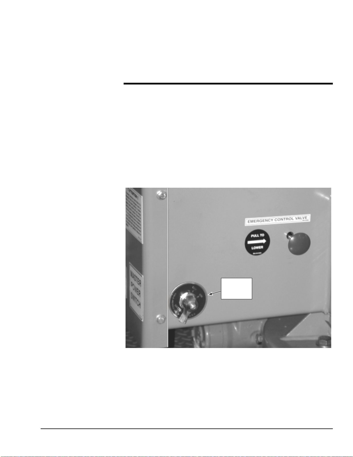
BATTERY ON/OFF Switch
A BATTERY ON/OFF switch (Figure 3-1) is mounted on the front end of the hydraulic
power compartment. Turn the switch to the ON position to turn battery power on to the
boom lift electrical system. Turn the switch to the OFF position to conserve battery power
when the lift is not in use.
BATTERY
ON/OFF
SWITCH
Figure 3-1. Battery ON/OFF Switch

XLB-4725A
3-2
Lower Control Panel
The lower control panel (Figure 3-2) is located on the side of the hydraulic power com-
partment. The following controls and indicators are on the lower control panel.
Figure 3-2. Lower Control Panel (DC Model)
HOUR Meter
The HOUR meter displays the elapsed time that the boom lift has been in operation
(UP/DOWN or ROTATION switches engaged). Display units are in hours and tenths.
PLATFORM/OFF/GROUND Key Switch
The PLATFORM/OFF/GROUND key switch enables boom lift control from either the
lower control panel or the work platform. Removing the key disables lift operation.
EMERGENCY STOP Pushbutton
When pressed, the EMERGENCY STOP pushbutton disconnects electrical power to the
upper and lower control panels. The EMERGENCY STOP pushbutton should only be
pressed to immediately stop all boom lift motion. To resume control, rotate the pushbut-
ton clockwise to disengage the emergency stop switch contacts.
OUTRIGGERS Indicator
The OUTRIGGERS indicator lights up when the boom outriggers are properly deployed
and the boom weight is removed from the trailer axle.

3 — OPERATION
3-3
UPPER BOOM UP/DOWN Selector Switch
Holding the UPPER BOOM UP/DOWN selector switch in the UP position enables the
upper boom to rise. Holding the selector switch in the DOWN position enables the upper
boom to descend. Turning the SPEED CONTROL rheostat clockwise starts the boom
motion. The up or down boom motion continues until the rheostat is released, the selector
switch is released, or the upper boom reaches a hard stop or a safe travel limit.
ROTATION CW/CCW Selector Switch
Holding the ROTATION CW/CCW selector switch in the CW position enables the boom
to rotate in the clockwise direction. Holding the selector switch in the CCW position en-
ables the boom to rotate in the counterclockwise direction. Turning the SPEED
CONTROL rheostat clockwise starts the boom motion. Rotation continues until the rheo-
stat or the selector switch is released.
LOWER BOOM UP/DOWN Selector Switch
Holding the LOWER BOOM UP/DOWN selector switch in the UP position raises the
lower boom. Holding the selector switch in the DOWN position lowers the lower boom.
Turning the SPEED CONTROL rheostat clockwise starts the selected boom motion. The
up or down boom motion continues until the rheostat is released, the selector switch is re-
leased, or the lower boom reaches a hard stop or a safe travel limit.
SPEED CONTROL Rheostat
A BOOM UP/DOWN or ROTATION selector switch must be held in a motion-enable
position to enable the SPEED CONTROL rheostat. Turn the SPEED CONTROL rheo-
stat clockwise to start boom motion. All boom motion speeds ramp up electronically.
Turn the rheostat farther clockwise to increase the boom motion speed.
Lower Control Panel – Gas Model Only
The following engine controls are included on the lower control panel of the gas model
boom lift. These controls are not shown.
CHOKE Pushbutton
Pressing the CHOKE pushbutton engages the choke solenoid. For cold starting, press the
CHOKE pushbutton in for about 5 seconds while cranking the engine.
ENGINE START/STOP Selector Switch
Holding the START/STOP selector switch in the START position cranks the engine. The
engine should not be cranked longer than 15 seconds at a time. Over-cranking will burn
up the starter motor.
Holding the START/STOP selector switch in the STOP position stops the engine. The se-
lector switch must be held down until the engine stops running.
XLB-4725A
3-4
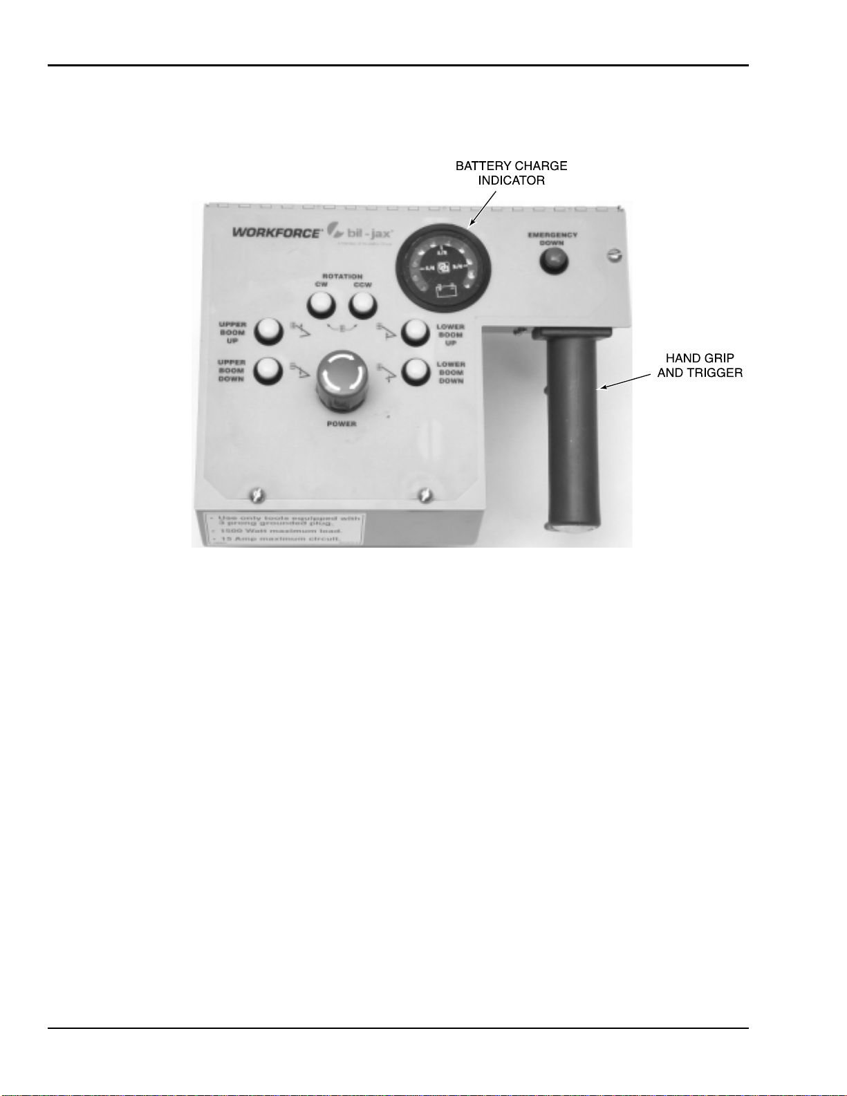
Upper Control Panel
The upper control panel (Figure 3-3) is mounted in the work basket. The following con-
trols and indicators are available on the upper control panel.
Figure 3-3. Upper Control Panel (DC Model)
UPPER BOOM UP/DOWN Pushbuttons
Pressing the UPPER BOOM UP pushbutton enables the upper boom to rise. Pressing the
UPPER BOOM DOWN pushbutton enables the upper boom to descend. Squeezing the
hand grip trigger starts the boom motion. The up or down boom motion continues until
the trigger is released, the pushbutton is released, or the upper boom reaches a hard stop
or a safe travel limit.
ROTATION CW/CCW Pushbuttons
Pressing the ROTATION CW pushbutton enables the boom to rotate in the clockwise di-
rection. Pressing the ROTATION CCW pushbutton enables the boom to rotate in the
counterclockwise direction. Squeezing the hand grip trigger starts the boom motion. Rota-
tion continues until the trigger is released or the pushbutton is released.
LOWER BOOM UP/DOWN Pushbuttons
Pressing the LOWER BOOM UP pushbutton enables the lower boom to rise. Pressing
the LOWER BOOM DOWN pushbutton enables the lower boom to descend. Squeezing
the hand grip trigger starts the boom motion. The up or down boom motion continues un-
til the trigger is released, the pushbutton is released, or the lower boom reaches a hard
stop or a safe travel limit.
Table of contents
Other BilJax Boom Lift manuals


Popular Boom Lift manuals by other brands

Oshkosh Corporation
Oshkosh Corporation JLG 600S Service and maintenance manual

Terex
Terex Genie S65XCD-1251 Operator's manual

Terex
Terex Genie Z-34/22 IC Service and repair manual

Pacific
Pacific Orchard-Rite MONOBOOM 9600 Series owner's manual

ALMAC
ALMAC BiBi 1090-BL Light TRANSLATION OF ORIGINAL INSTRUCTIONS

Genie
Genie Z-30 Operator's manual


