BilJax FALCON 125 Building instructions
Service and Parts
Manual
AERIAL WORK PLATFORMS
FALCON 125
Self Propelled Hydraulic Boom Lift
B33-01-0083

BOOM PERSONNEL LIFT
This equipment is designed and manufactured in compliance with the duties, re-
sponsibilities, and standards set forth for manufacturers in the ANSI 92.5 standard
in effect at the time of manufacture.
This equipment will meet or exceed applicable OSHA codes and ANSI A92.5 stan-
dards when used in accordance with sections 5, 6, 7, 8, 9, & 10 of ANSI A92.5 and
all other manufacturer’s recommendations.
It is the responsibility of the user of this equipment to follow all applicable ANSI,
OSHA, Federal, State, and local codes and regulations that govern the safe opera-
tion of this equipment.

i
Table of Contents
Preface.................................................................................................................v
1Safety................................................................................................................1-1
1-1 Introduction.........................................................................................1-1
1-2 Maintenance Safety.............................................................................1-2
General Maintenance......................................................................1-2
Battery Maintenance.......................................................................1-3
1-3 Damaged Equipment Policy ...............................................................1-3
Safety Statement.............................................................................1-3
Damage Policy................................................................................1-3
Damage Repair Notice....................................................................1-3
2Introduction.....................................................................................................2-1
2-1 General Description ............................................................................2-1
2-2 Specifications......................................................................................2-2
Boom Lift Work Platform ..............................................................2-2
2-3 Warranty .............................................................................................2-3
3Maintenance ....................................................................................................3-1
3-1 Scheduled Service Checks ..................................................................3-1
Daily/Weekly Service Checks ........................................................3-1
Monthly Service Checks.................................................................3-2
3-2 Lubrication..........................................................................................3-3
3-3 Hydraulic System................................................................................3-3
Hydraulic System Inspection..........................................................3-3
Fluid Check and Replacement........................................................3-4
Return Filter Replacement..............................................................3-5
Bleeding Air From Hydraulic System ............................................3-6
Hydraulic System Flow Control Adjustments................................3-6
Hydraulic Pressure Checks and Adjustments...............................3-12
3-4 Adjust Boom Rotation Chain............................................................3-18
3-5 Adjust Lift Vehicle Drive Chains .....................................................3-19
Check/Adjust Secondary Drive Chain Tension............................3-19
Check/Adjust Primary Drive Chain Tension................................3-20
3-6 Boom Rotation Bearings...................................................................3-22
Check Free Play............................................................................3-22
3-7 Limit Switch Checks and Adjustments.............................................3-23
Adjusting Boom Down Limit Switch...........................................3-23
Adjusting Function Limit Switch .................................................3-24
3-8 Material Safety Data Sheets..............................................................3-25

ii
4Troubleshooting.............................................................................................. 4-1
4-1 Troubleshooting ................................................................................. 4-1
Troubleshooting Flowcharts .......................................................... 4-1
4-2 Troubleshooting Flowcharts .............................................................. 4-5
Gasoline Engine Will Not Turn Over ............................................ 4-6
Gasoline Engine Turns Over But Will Not Start ........................... 4-7
Electric Motor Will Not Start ........................................................ 4-8
Electric Motor Will Not Stay Running .......................................... 4-9
Green Light Does Not Turn On When Outriggers Are Down..... 4-10
Alarm Sounds With Boom Lift Level.......................................... 4-11
Green Light Comes On But Goes Out ......................................... 4-12
Basket Control Boom Function Fails........................................... 4-13
Ground Control Boom Function Fails ......................................... 4-14
Boom Lift Functions Are Slow Or Erratic................................... 4-15
All Hydraulic Functions Fail ....................................................... 4-15
Hydraulic Drive Function Fails ................................................... 4-17
Outrigger Function Fails.............................................................. 4-18
Boom Function Fails.................................................................... 4-19
4-3 Troubleshooting Aids....................................................................... 4-20
5Replacement Decals........................................................................................ 5-1
6Parts List......................................................................................................... 6-1
6-1 Chassis Drive Components ................................................................ 6-2
6-2 Boom Rotation Components .............................................................. 6-4
6-3 Chassis Electrical and Hydraulics ...................................................... 6-6
6-4 Electric Motor and Pump ................................................................... 6-8
6-5 Gasoline Engine and Pump .............................................................. 6-12
6-6 Outriggers ........................................................................................ 6-16
6-7 Lower Boom Components ............................................................... 6-18
6-8 Upper Boom Components................................................................ 6-20
6-9 Boom Extension Components.......................................................... 6-22
6-10 Troughs, Trough Covers, and Supports ........................................... 6-24
6-11 Basket Components.......................................................................... 6-26
6-12 Upper Controls................................................................................. 6-28
6-13 Lower Control Station...................................................................... 6-30
6-14 Chassis Covers and Panels............................................................... 6-34
6-15 Rotation Hydraulics ......................................................................... 6-36
6-16 Outrigger and Drive Hydraulics....................................................... 6-38
6-17 Boom Control Hydraulics, Ground.................................................. 6-40
6-18 Boom Control Hydraulics, Basket ................................................... 6-42
6-19 Lower Boom Hydraulics.................................................................. 6-44
6-20 Upper Boom Hydraulics .................................................................. 6-46
6-21 Drive Hydraulics .............................................................................. 6-48
6-22 Chassis Electrical Box Components ................................................ 6-50
6-23 Pushbutton Panel Components, Ground Station .............................. 6-52
6-24 Pushbutton Panel Components, Basket Station................................ 6-53
7ANSI Reprint.................................................................................................. 7-1

iii
List of Illustrations
Figure 3-1. Hydraulic Reservoir Breather/Dipstick...................................................3-4
Figure 3-2. Return Filter Assembly ...........................................................................3-5
Figure 3-3. Ground Station Flow Controls ................................................................3-7
Figure 3-4. Upper Beam Lowering Flow Control Valve...........................................3-8
Figure 3-5. Lower Beam Lowering Flow Control Valve...........................................3-9
Figure 3-6. Boom Rotate Flow Control Valves .......................................................3-10
Figure 3-7. Basket Tilt Flow Control Valve ............................................................3-11
Figure 3-8. Main Bypass Valve and Pressure Test Port ..........................................3-12
Figure 3-9. Boom Lift Bypass Valve .......................................................................3-14
Figure 3-10. Extend Bypass Valve ............................................................................3-15
Figure 3-11. Basket Tilt Bypass Valves ....................................................................3-16
Figure 3-12. Boom Rotation Chain............................................................................3-18
Figure 3-13. Chain Inspection Port............................................................................3-19
Figure 3-14. Secondary Drive Chains Adjustment....................................................3-20
Figure 3-15. Motor Bracket Screws...........................................................................3-21
Figure 3-16. Primary Chain Adjust Screw and Lock Nut..........................................3-21
Figure 3-17. Slew Bearings Wear Measurement .......................................................3-22
Figure 3-18. Boom Down Limit Switch ....................................................................3-23
Figure 3-19. Function Limit Switch...........................................................................3-24
Figure 4-1. Electrical Box Components.....................................................................4-4
Figure 4-2. Level Sensor..........................................................................................4-20
Figure 4-3. Simplified Electrical Schematic ............................................................4-21
Figure 4-4. Wiring Diagram ....................................................................................4-22
Figure 4-5. Hydraulic Diagram................................................................................4-24
Figure 5-1. Replacement Decals................................................................................5-2
Figure 5-2. Decal Locations.......................................................................................5-5
Figure 6-1. Chassis Drive Components .....................................................................6-2
Figure 6-2. Boom Rotation Components ...................................................................6-4
Figure 6-3. Chassis Electrical and Hydraulics...........................................................6-6
Figure 6-4. Electric Motor and Pump ........................................................................6-8
Figure 6-5. Gasoline Engine and Pump ...................................................................6-12
Figure 6-6. Outriggers .............................................................................................6-16
Figure 6-7. Lower Boom Components ....................................................................6-18
Figure 6-8. Upper Boom Components.....................................................................6-20
Figure 6-9. Boom Extension Components...............................................................6-22
Figure 6-10. Troughs, Trough Covers, and Supports ................................................6-24
Figure 6-11. Basket Components...............................................................................6-26
Figure 6-12. Upper Controls......................................................................................6-28
Figure 6-13. Lower Control Station...........................................................................6-30
Figure 6-14. Chassis Covers and Panels....................................................................6-34
Figure 6-15. Rotation Hydraulics ..............................................................................6-36
Figure 6-16. Outrigger and Drive Hydraulics............................................................6-38
Figure 6-17. Boom Control Hydraulics, Ground.......................................................6-40
Figure 6-18. Boom Control Hydraulics, Basket ........................................................6-42
Figure 6-19. Lower Boom Hydraulics.......................................................................6-44
Figure 6-20. Upper Boom Hydraulics .......................................................................6-46
Figure 6-21. Drive Hydraulics ...................................................................................6-48
Figure 6-22. Chassis Electrical Box Components .....................................................6-50
Figure 6-23. Ground Station Pushbutton Panel Components ....................................6-52
Figure 6-24. Basket Station Pushbutton Panel Components......................................6-53

iv
List of Tables
Table 2-1. Specifications ......................................................................................... 2-2
Table 3-1. Daily/Weekly Service Checks................................................................ 3-1
Table 3-2. Monthly Service Checks ........................................................................ 3-2
Table 3-3. Cylinder Operating Speeds, Factory Settings......................................... 3-6
Table 3-4. Hydraulic Pressure, Factory Settings ................................................... 3-12
Table 4-1. Electrical Components – Functional Description................................... 4-2
Table 4-2. Level Sensor LEDs............................................................................... 4-20
Table 5-1. Replacement Decals ............................................................................... 5-1
Table 6-1. Chassis Drive Components Parts List .................................................... 6-3
Table 6-2. Boom Rotation Components Parts List .................................................. 6-5
Table 6-3. Chassis Electrical and Hydraulics Parts List .......................................... 6-7
Table 6-4. Electric Motor and Pump Parts List ....................................................... 6-9
Table 6-5. Gasoline Engine and Pump Parts List .................................................. 6-13
Table 6-6. Outriggers Parts List............................................................................. 6-17
Table 6-7. Lower Boom Components Parts List ................................................... 6-19
Table 6-8. Upper Boom Components Parts List.................................................... 6-21
Table 6-9. Boom Extension Components Parts List.............................................. 6-23
Table 6-10. Troughs, Trough Covers, and Supports Parts List ............................... 6-25
Table 6-11. Basket Components Parts List.............................................................. 6-27
Table 6-12. Upper Controls Parts List ..................................................................... 6-29
Table 6-13. Lower Control Station Parts List.......................................................... 6-31
Table 6-14. Chassis Covers and Panels Parts List ................................................... 6-35
Table 6-15. Rotation Hydraulics Parts List.............................................................. 6-37
Table 6-16. Outrigger and Drive Hydraulics Parts List........................................... 6-39
Table 6-17. Boom Control Hydraulics, Ground Parts List ...................................... 6-41
Table 6-18. Boom Control Hydraulics, Basket Parts List........................................ 6-43
Table 6-19. Lower Boom Hydraulics Parts List ...................................................... 6-45
Table 6-20. Upper Boom Hydraulics Parts List....................................................... 6-47
Table 6-21. Drive Hydraulics Parts List .................................................................. 6-49
Table 6-22. Chassis Electrical Box Components Parts List..................................... 6-51
Table 6-23. Ground Station Pushbutton Panel Parts List ........................................ 6-52
Table 6-24. Basket Station Pushbutton Panel Parts List.......................................... 6-53
Table 7-1. Minimum Safe Approach Distance (M.S.A.D.) to energized
(exposed or insulated) power lines and parts. ...................................... 7-14

PREFACE
The purpose of this manual is to provide a thorough understanding of the Falcon 125 Self
Propelled Hydraulic Boom Lift operation and controls. Read the safety and operating
instructions in this manual and become familiar with the location and use of all controls.
Follow all warnings, cautions, and instructions in this manual and any attached to and
supplied with the boom lift. All OSHA, ANSI, state, and local codes and regulations
concerning this equipment should obtained, read, and thoroughly understood before
attempting to operate this equipment.
To ensure proper and safe use of this equipment, only trained and qualified personnel
should operate and maintain the boom lift.
SAFETY NOTES
This manual contains DANGERS, WARNINGS, CAUTIONS, and NOTES that must be
followed to prevent the possibility of improper service, personnel injury or death, and
damage to equipment.
DANGER
Dangers warn of equipment operation near electrical power lines that could lead to
personal injury or death.
WARNING
Warnings describe conditions or practices that could lead to personal injury or
death.
CAUTION
Cautions provide information important to prevent errors that could damage
machine or components.
NOTE: Notes contain additional information important to a procedure.
v

vi

1-1
1
Safety
1-1
ip-
me-
sense in the operation of mechanical equipment is the best
s
implemented at all
considered as legal advice and is intended
to
For any questions concerning the safe use of this equipment, call 419.445.9675 before
operating.
INTRODUCTION
Familiarity and proper training are required for the safe operation of mechanical equ
ment. Equipment operated improperly or by untrained personnel can be dangerous. Read
the operating instructions in this manual and become familiar with the location and
proper use of all controls. Inexperienced operators should receive instruction from so
one familiar with the equipment before being allowed to operate the machine. The use of
intelligence and common
practice in any safety policy. Be professional and always observe the safety procedure
set forth in this manual.
All OSHA, ANSI, state, and local codes and regulations pertaining to this equipment
should be obtained, read, and thoroughly understood before attempting to operate this
equipment. Persons under the influence of drugs, alcohol, or prescription medication
should not be on or near this equipment. Common sense should be
times during the use of this equipment. Do not operate this equipment in areas where the
equipment or user may come in contact with a live power source.
The information contained herein is not to be
for informational purposes only. This information is offered to alert Bil-Jax customers
procedures that may be of concern to them.
This information is not intended to be all inclusive and is to be followed in the use of
Bil-Jax equipment only.

FALCON 125
1-2
1-2 MAINTENANCE SAFETY
Ensure the following safety precautions are observed whenever maintenance is per-
formed on the Falcon 125 Hydraulic Boom Lift.
General Maintenance
• ALWAYS perform maintenance procedures according to manufacturer's re-
quirements. NEVER short change maintenance procedures.
• ALWAYS check hydraulic system. Make sure all lines, connectors, and fittings
are tight and in good condition.
• ALWAYS turn the key switch off before connecting or disconnecting wiring to
or from valve solenoids or other load devices.
• ALWAYS disconnect power to the hydraulic pump drive motor before making
checks of the hydraulic valves.
• ALWAYS keep all mechanisms properly adjusted and lubricated according to
maintenance schedule and manufacturer’s specifications.
• ALWAYS perform a function check of operating controls before each use and
after repairs have been made.
• ALWAYS locate and protect against possible pinch points prior to performing
maintenance and repairs.
• ALWAYS use factory-approved parts to repair or maintain this equipment. If
this equipment is rebuilt, retesting is required in accordance with factory
instructions.
• NEVER allow water or foreign particles into the electric motor housing. Inges-
tion of water or foreign particles may cause serious damage to the motor. If the
motor gets wet, oven dry the motor to remove all moisture before operating;
consult motor manufacturer for drying instructions.
• NEVER test or operate the hydraulic components when another person is near
the equipment.
• NEVER add unauthorized fluids to the hydraulic system or battery. Check origi-
nal manufacturer specifications.
• NEVER exceed the manufacturer's recommended relief valve settings.
• NEVER touch or allow metal tools to contact static discharge sensitive elec-
tronic components. ALWAYS use static discharge prevention mats and ground-
ing devices when handling electronic components.
• NEVER tamper with cylinder load holding valves. Contact the Bil-Jax Service
Department at 419.445.9675 if the cylinder load holding valves need adjusting.
• NEVER attempt repairs you do not understand. Consult manufacturer if you
have any questions regarding proper maintenance, specifications, or repair.

1 — SAFETY
1-3
Battery Maintenance
Ensure the following general safety precautions are followed whenever performing bat-
tery maintenance on the Falcon 125 Hydraulic Boom Lift.
• ALWAYS check battery acid level monthly. Check battery test indicator for
proper state of charge on maintenance free batteries before using lift.
• ALWAYS wear safety glasses when working near battery.
• ALWAYS avoid contact with battery acid. Battery acid causes serious burns.
Avoid contact with skin or eyes. If accidental contact occurs, flush with water
and consult a physician immediately.
• ALWAYS disconnect ground cable first when removing battery.
• ALWAYS connect ground cable last when installing battery.
• ALWAYS charge batteries in open, well-ventilated areas.
• NEVER smoke when servicing battery.
• NEVER allow batteries to overcharge and boil.
• NEVER short across battery posts to check for current. NEVER break a live cir-
cuit at battery.
• NEVER jump start other vehicles using boom lift battery.
1-3 DAMAGED EQUIPMENT POLICY
Safety Statement
At Bil-Jax, we are dedicated to the safety of all users of our products. Therefore, all
Bil-Jax lifts are designed, manufactured, and tested to comply with current applicable
Federal OSHA and ANSI codes and regulations.
Damage Policy
There may be occasions when a Bil-Jax lift is involved in an incident that results in struc-
tural damage to the lift. This can seriously compromise the ability of the lift to perform in
a safe manner. Therefore, whenever a Bil-Jax lift is damaged structurally, or when there
is the possibility of structural damage (this damage may be internal and is not always
visible to the naked eye), Bil-Jax requires that the lift be returned to our facility at 125
Taylor Parkway, Archbold, Ohio, for reconditioning. If you have any questions concern-
ing what constitutes structural damage, please call the Bil-Jax Service Department at
419.445.9675.
Damage Repair Notice
There may be occasions when a Bil-Jax lift is involved in an incident resulting in non-
structural damage. When this occurs and repairs are made by the owner or area distribu-
tor, please notify Bil-Jax of these non-maintenance repairs and request a repair form to
be filled out and returned to Bil-Jax.

FALCON 125
1-4

2-1
2
Introduction
2-1
er.
ith hydraulic pump. Gas powered op-
l
ex-
selected boom motion reaches an operating limit, the motion ceases and another
n
a
.
dur-
y familiar with the operating controls of the Falcon 125 Hydrau-
lic Boom Lift, please refer to the Operation Manual, Part No. B33-01-0082, before work-
ing on this equipment.
GENERAL DESCRIPTION
The Falcon 125 Hydraulic Boom Lift is designed and manufactured for positioning per-
sonnel with their tools and equipment at overhead work locations. The rated work basket
load capacity is 300 lbs. Basket elevation is by hydraulic cylinders acting on lower and
upper boom sections. The upper boom also extends by the action of a hydraulic cylind
A hydraulic cylinder, drive chain, and sprocket rotates the boom around a vertical axis.
The hydraulic system is powered by a 13 horsepower gasoline engine with hydraulic
pump or by a separate 120 volt AC electric motor w
eration allows use of the boom lift away from an electrical power source. The electrica
power system allows use of the boom lift indoors.
Two control stations use motion enable switches and proportional hydraulic valves to
control the direction and speed of boom lift and rotation. One set of operator controls is
provided for ground operation and another set is provided for operation from the basket.
Elevation and rotation controls are operational only when the outriggers are correctly
tended and the boom lift is level. Only one boom motion is permitted at a time, and only
as long as the boom is level and the vehicle load is supported by all four outriggers.
When a
motion must be selected. No outrigger can be retracted while the upper or lower boom is
raised.
Boom elevation speeds are adjustable from zero to 1.2 feet per second (36.6 cm/sec). I
case of a hydraulic hose failure at either retract-cylinder port, a load holding valve will
stop the return oil flow. It is strongly recommended that no one adjust or tamper with
these safety devices. If service is required, please notify Bil-Jax for detailed instructions.
Emergency lowering of the basket is by manual operation of valve plungers and levers
on the upper and lower boom lift cylinders from the ground, or by pushbutton and valve
lever operation in the basket. From the ground operating station, firmly pushing in and
holding a valve plunger and engaging the related valve lever manually retracts the boom
lift cylinder. In the basket, pressing an emergency lowering pushbutton while engaging
single hydraulic valve lever enables boom lowering in case of a hydraulic power failure
Manual boom rotation is enabled from the ground by opening a valve and pushing the
boom around the boom rotation centerline.
The Falcon 125 boom lift, extension, and outrigger cylinders will not rust or corrode
ing storage since the cylinder rod is fully immersed in oil. It is important that the cylinder
rods be kept clean and undamaged for the protection of the cylinder head packings.
If you are not thoroughl

FALCON 125
2-2
2-2 SPECIFICATIONS
Boom Lift Work Platform
Model Number: Falcon 125 Serial Number ________________
Manufactured by: Bil-Jax, Inc.
125 Taylor Parkway
Archbold, Ohio 43502
419.445.9675
Table 2-1. Specifications
Feature Data
Gross Vehicle Weight 3112 lbs (1412 kg)
Rated Platform Load 300 lbs (135 kg) total or
1 occupant plus 120 lbs (44.8 kg)
Support Surface Load Capacity 6000 lb/ft2(2.9 kg/cm2) minimum
Maximum Work Height, Nominal 41 ft (12.5 m)
Maximum Platform Height 35 ft 5 in. (10.7 m 12.7 cm)
Maximum Outreach 19 ft (5.8 m)
Elevation Rate, Nominal 1.2 ft/sec (36.6 cm/sec)
Boom Rotation 357° non-continuous
Rotation Speed 430° per minute, nominal
Drive Speed 105 ft/min (32 m/min) nominal
Basket Dimensions (WxDxH) 34 in. x 25.5 in. x 44.5 in. (86 cm x 65 cm x 113
cm)
On-Board Power Source 12 Volt DC, deep cycle
Auxiliary Power Required 110/120 Volts AC, 60 Hz, 40 Amp
Hydraulic Pressures, Maximum Drive/Boom Lift 2756 psi (190 bar) [19 000 kPa]
Rotate 1885 psi (130 bar) (13 000 kPa)
Hydraulic Reservoir Capacity 5.25 Gallons (20 Liters)
Hydraulic System Capacity 10.5 Gallons (40 Liters)
Hydraulic Oil Energol HLP-HD46 (BP Oil)
Low Operating Temperature -11°F (-24°C)
Transport Dimensions (LxWxH) 16.3 ft x 3.2 ft x 5.9 ft (5.0 m x 0.96 m x 1.8 m)

2 — INTRODUCTION
2-3
2-3 WARRANTY
Bil-Jax warrants its boom lifts for one year from the date of delivery against all defects of
material and workmanship, provided the unit is operated and maintained in compliance
with Bil-Jax’s operating and maintenance instructions. Bil-Jax will, at its option, repair
or replace any unit or component part which fails to function properly in normal use.
This warranty does not apply if the lift and/or its component parts have been altered,
changed, or repaired without the consent of Bil-Jax or by anyone other than Bil-Jax or its
factory trained personnel, nor if the lift and/or its components have been subjected to
misuse, negligence, accident or any conditions deemed other than those considered as
occurring during normal use.
Components not manufactured by Bil-Jax are covered by their respective manufacturer’s
warranties. A list of those components and their warranties is available upon written re-
quest to Bil-Jax.
Bil-Jax shall not in any event be liable for the cost of any special, indirect, or consequen-
tial damages to anyone, product, or thing. This warranty is in lieu of all other warranties
expressed or implied. We neither assume nor authorize any representative, or other per-
son, to assume for us any other liability in connection with the sale, rental, or use of this
product.

FALCON 125
2-4
3-1
3
Maintenance
3-1 HECKS
Perform the following .
/Weekly Service Chec
before use Weekly
SCHEDULED SERVICE C
Daily/Weekly Service Checks
daily/weekly service checks as listed in Table 3-1
Table 3-1. Daily ks
Service Check Daily
Check to see that all decals are present.
Check that controls and indicators at ground and basket
control stations operate properly.
Raise booms and turn master power switch off. Verify t
inders remain stable and do not dri
hat
ft.
boom and outrigger cyl
Check that boom down limit switch operates properly.
Check/add engine oil.
Check engine air filter element. Clean or replace dirty or
damaged air filter element.
Check tires for proper inflation. When cold, tires should be
inflated to 42 psi (2,9 bar).
Check work platform mounting hardware
Check electrical wiring for cuts, loose terminals, broken
wires, chaffing, corrosion, or other damage. Repair all
damage, remove corrosion, and seal exposed connections.
Lubricate grease fittings labeled LUBRICATE WEEKLY
with NLGI Grade 2 multi-purpose grease per paragraph 3-2.
Check boom lift for missing or loose hardware. Replace or
tighten missing or loose hardware as needed.

FALCON 125
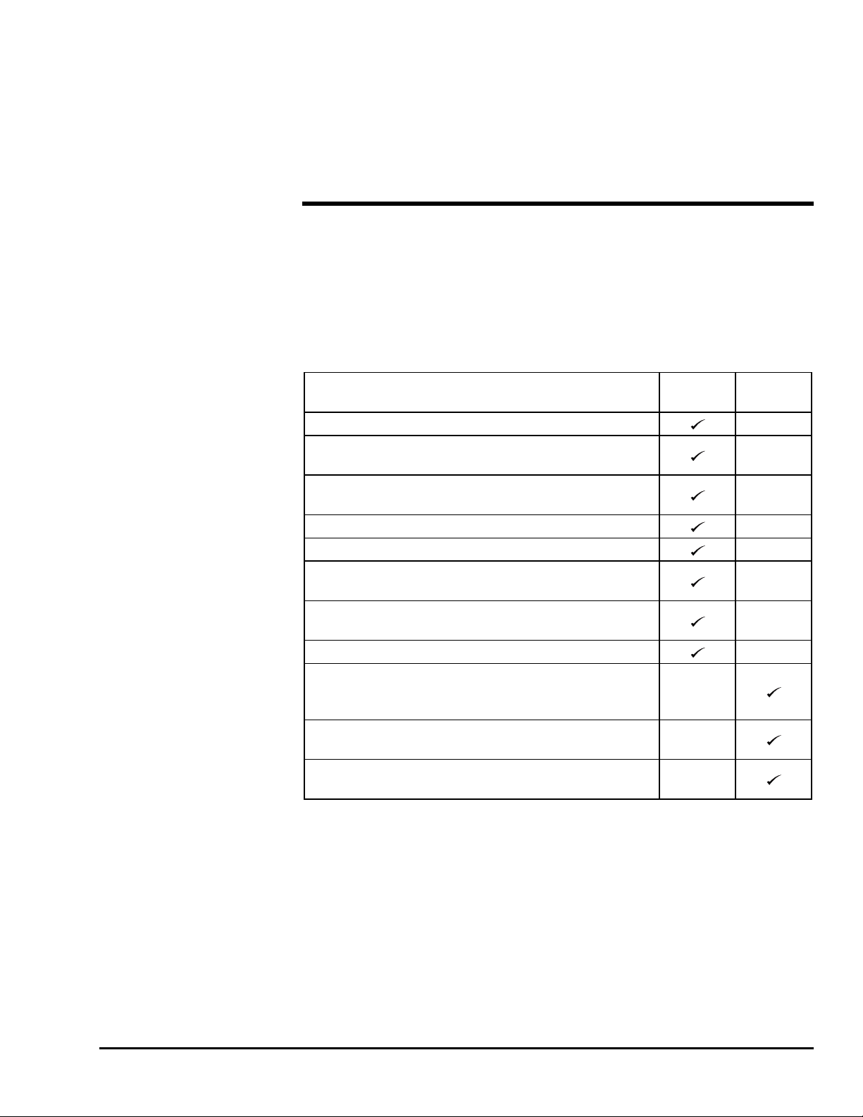
Monthly Service Checks
Perform the following monthly service checks as listed in Table 3-2.
Table 3-2. Monthly Service Checks
Service Check Every
month Every
6 months Every
12 months
Check/add hydraulic oil per paragraph 3-3.
Check hydraulic hoses, lines, and fittings per
paragraph 3-3.
Clean battery terminals and check battery
charger operation.
Check operation of manual lowering valves.
Check operation of hydraulic cylinders and
load holding valves.
Check battery electrolyte level. If battery
charge is low, add water to bring electrolyte
just above plates. If batteries are fully charged,
raise electrolyte to full mark in each cell.
Check battery cables and wiring for loose
connections and damaged wires.
Check/clean engine fuel sediment cup.
Change engine oil.
Clean spark plug; adjust plug gap if necessary.
Replace engine air filter element.
Inspect wheel bearings for damage.
Replace spark plug.
Check/adjust hydraulic oil pressure.
Replace hydraulic oil and filter.
Check and adjust boom rotation chain per
paragraph 3-4.
Check and adjust lift vehicle drive chains per
paragraph 3-5.
Check and adjust boom rotation speed per
paragraph 3-3.
Check and adjust boom lowering speed per
paragraph 3-3.
Check boom rotation bearings for wear per
paragraph 3-6. Replace worn or damaged
bearings.
Load test boom lift operations with 300
pounds (135 kg).
3-2

3 — MAINTENANCE
3-2 LUBRICATION
Lubrication makes operation of the Falcon 125 Boom Lift more efficient and extends the
equipment life.
All grease fittings on the Falcon 125 Boom Lift are labeled LUBRICATE WEEKLY
with NLGI Grade 2 multi-purpose grease. There are 20 grease fittings. At each grease fit-
ting, wipe off any dirt and grease residue and add approximately ½ ounce (15 cc) of
grease to the fitting.
3-3 HYDRAULIC SYSTEM
Hydraulic system maintenance varies with equipment use and the environment in which
the boom lift is used. Constant attention to keep the oil clean and the reservoir properly
filled will help prevent possible damage to the system. Hydraulic diagrams are provided
at the end of this section for general reference.
WARNING
Hydraulic system flow and pressure settings are factory settings and should not
need readjustment. The only time readjustment is needed is when a component in
the hydraulic control circuit is replaced. Only the adjustments covered in this
manual are permitted. If you believe that any other hydraulic component needs
adjustment, notify Bil-Jax for additional instruction. Hydraulic motions are
quiet, quick, and can be dangerous to persons on or near the lift vehicle. Failure to
heed this warning can result in serious injury or death.
Hydraulic System Inspection
Check the hydraulic hoses, lines, and fittings for leaks and damage. Tighten or replace as
necessary to prevent hydraulic oil loss. Secure hoses and lines as needed to prevent rub-
bing and chafing.
3-3

FALCON 125
Fluid Check and Replacement
Remove the chassis cover plate to access the hydraulic reservoir, Figure 3-1. The hydrau-
lic oil level should be checked with the oil warm and the engine off. Hydraulic cylinders
should be retracted, the boom down and the outriggers raised.
Remove the breather dipstick and wipe off any oil with a clean shop cloth. Reinsert the
dipstick and tighten. Remove and check the oil level. The oil level should be between the
full and add oil marks on the dipstick.
The reservoir is originally filled with ISO VG 20…32 hydraulic oil. Do not mix hydrau-
lic oils.
HYDRAULIC
RESERVOIR
HYDRAULIC
FILTER
BREATHER
DIPSTICK
FULL
ADD
OIL
Figure 3-1. Hydraulic Reservoir Breather/Dipstick
3-4
Table of contents
Other BilJax Boom Lift manuals


Popular Boom Lift manuals by other brands


Terex
Terex Genie GS-3384 Operator's manual

Oshkosh Corporation
Oshkosh Corporation JLG X26JPLUS Operator, safety, and general maintenance manual

Sinoboom
Sinoboom TB32JN Plus Operation manual

JLG
JLG TOUCAN 1010 I Operation and safety manual

JLG
JLG 450A Operator's and safety manual

Upright
Upright AB38 Operator's manual