Billy Goat SC180H User manual

Part No 371508 Form No F091113A
1
SC180H Owner’s Manual
BILLY GOAT SOD CUTTER
Owner's Manual
SC180H

Part No 371508 Form No F091113A
2
SC180H Owner’s Manual
ABOUT THIS MANUAL
THANK YOU for purchasing a BILLY GOAT ®Sod Cutter. Your new machine has been carefully designed and
manufactured to provide years of reliable and productive service. This manual provides complete operating and
maintenance instructions that will help to maintain your machine in top running order. Read this manual carefully
before assembling, operating, or servicing your equipment.
CONTENTS
SERIAL PLATE DATA AND SPECIFICATIONS 3
GENERAL SAFETY 4-5
SOUND AND VIBRATION 6
INSTRUCTION LABELS 7
PACKING CHECKLIST & ASSEMBLY _______ 8
OPERATION CONTROLS/OPERATION 9-10
MAINTENANCE 11-12
TROUBLESHOOTING AND WARRANTY PROCEDURE 13
ILLUSTRATED PARTS & PARTS LISTS 14-23
Go to http://www.billygoat.com for French-Canadian translations of the product manuals.
Visitez http://www.billygoat.com pour la version canadienne-française des manuels de produits

Part No 371508 Form No F091113A
3
SC180H Owner’s Manual
SERIAL PLATE DATA
Record the model number, serial number, date of
purchase, and where purchased.
Purchase Date:
Purchased From:
Specifications
SC180H
Engine: HP
5.5 HP (4.1 kw)
Engine: Model
GXV160UH2N1AH
Engine: Type
Honda
Engine: Fuel Capacity
1.6 qt. (1.5 L)
Engine: Oil Capacity
0.69 qt. (0.65 L)
Total Unit Weight:
348# (158 Kg)
Max. operating slope
20o
Overall length
54” (1371mm)
Overall width
26.5” (660mm)
Overall height
36.5” (927mm)
In accordance with 2000/14/EEC
104dBa
Sound at operators position
84dBa
Vibration at operator position
2.5g (24.8m/s2)

Part No 371508 Form No F091113A
4
SC180H Owner’s Manual
GENERAL SAFETY INSTRUCTIONS and SYMBOLS
The safety symbols shown below are used throughout this manual. You should become familiar with them before
assembling, operating, or servicing this equipment.
This symbol indicates important information that will prevent injury to yourself or others.
This symbol indicates ear protection is recommended when operating this equipment.
This symbol indicates eye protection is recommended when operating this equipment.
This symbol indicates gloves should be worn when servicing this equipment.
This symbol indicates that this manual and the engine manufacturer’s manual should be read
carefully before assembling, operation, or servicing this equipment.
This symbol indicates important information that will prevent damage to your BILLY GOAT ®
Sod Cutter.
This symbol indicates the engine oil level should be checked before operating this
equipment.
Read and make sure you thoroughly understand the following safety precautions before assembling, operating or
servicing this equipment:
READ this manual and the engine manufacturer’s manual carefully before assembling,
operating, or servicing this equipment.
EAR PROTECTION is recommended when operating this equipment.
EYE PROTECTION is recommended when operating this equipment.
BREATHING PROTECTION is recommended when operating this equipment.
EXHAUST from this product contains chemicals known to the State of California to cause
cancer, birth defects or other reproductive harm.
DO NOT operate this equipment on any unimproved forested, brushy, or grass covered land
unless a spark arrester is installed on the muffler as required by Section 4442 of the
California Public Resources Code. The arrester must be maintained in good working order.
Other states may have similar laws. Federal laws apply on federal lands.
DO NOT run engine in an enclosed area. Exhaust gases contain carbon monoxide, an
odorless and possibly fatal poison.

Part No 371508 Form No F091113A
5
SC180H Owner’s Manual
WARNING: IMPORTANT! This cutting machine is capable of amputating hands and feet and throwing objects.
Failure to observe the following safety instructions could result in serious injury or death.
DO NOT run this equipment indoors or in any poorly ventilated area. Refueling outdoors is recommended.
DO NOT refuel this equipment while the engine is running. Allow engine to cool for at least two minutes before
refueling.
DO NOT store gasoline near an open flame.
DO NOT remove gas cap while engine is running.
DO NOT start or operate engine if strong odor of gasoline is present.
DO NOT start or operate engine if gasoline is spilled. Move equipment away from spill until gasoline has completely
evaporated.
DO NOT smoke while filling the fuel tank.
DO NOT check for spark with spark plug or spark plug wire removed. Use an approved spark tester.
DO NOT operate engine without a muffler. Inspect muffler periodically and replace if necessary. If equipped with
muffler deflector, inspect deflector periodically and replace if necessary.
DO NOT operate engine with grass, leaves or other combustible material near the muffler.
DO NOT touch muffler, cylinder, or cooling fins when hot. Contact with hot surfaces may cause severe burns.
DO NOT leave equipment unattended while in operation.
DO NOT park equipment on a steep grade or slope.
DO NOT operate equipment with bystanders in or near the work area.
DO NOT allow children to operate this equipment.
DO NOT operate equipment with guards removed.
DO NOT operate equipment near hot or burning debris or any toxic or explosive materials.
DO NOT operate equipment on slopes greater than specified in Specifications section of this manual.
DO NOT operate barefoot or wearing open sandals. Always wear substantial footwear
DO NOT place hands or feet underneath unit, or near any moving parts.
DO NOT pull backwards unless absolutely necessary
DO NOT operate the Sod Cutter while under the influence of alcohol or drugs.
DO NOT use near drop-offs, ditches, or embankments. The operator could lose footing or balance
DO NOT use on excessively steep slopes.
DO NOT ride or climb or the machine while in operation.
DO NOT change the engine governor setting or overspeed the engine.
ALWAYS be sure of your footing; keep a firm hold on the handle and walk; never run.
ALWAYS Stop the blade(s) when crossing gravel drives, walks, or roads.
ALWAYS Shut the engine (motor) off and wait until the blade comes before servicing.
ALWAYS use only in daylight or good artificial light.
ALWAYS Disengage the drive lever and blade lever before starting the engine.
ALWAYS wear safety goggles or safety glasses with side shields
ALWAYS remove spark plug wire when servicing equipment to prevent accidental starting.
ALWAYS check fuel lines and fittings frequently for cracks or leaks. Replace if necessary.
ALWAYS store fuel in approved safety containers.
ALWAYS wear proper foot apparel when sod cutting.
WARNING: Important
Remove all rocks, wire, string, etc. that can present a hazard during work prior to starting.
DO identify and mark all fixed objects to be avoided during work such as sprinkler heads, water valves, limbs, or
clothes line anchors, etc.

Part No 371508 Form No F091113A
6
SC180H Owner’s Manual
SOUND
SOUND LEVEL 84 dB(a) at Operator Position
104 dB(a)
Sound tests were conducted in accordance with 2000/14/EEC, and were performed on 7-11-13 under the
conditions listed below.
Sound power level listed is the highest value for any model covered in this manual. Please refer to serial plate on
the unit for the sound power level for your model.
VIBRATION DATA
VIBRATION LEVEL 2.5 g (24.8 m/s2)
Vibration levels at the operator’s handles were measured in the vertical, lateral and longitudinal directions using
calibrated vibration test equipment. Tests were performed on 7-11-13 under the conditions listed below.
INTENDED USE
INTENDED USE: This machine may only be utilized for the purpose for which it was designed, i.e. to cut 18in (45.7
cm) wide strips of turf. Make sure that all operators of this equipment are trained in general machine use and safety.
During operation the lawn and turf are cut into strips. Should the cutter’s
wheels skid during use it is advisable to adjust the cutting depth. If this operation does
not prevent this occurrence check the state of the terrain. If it is too dry it should be
wetted so that the blade encounters a slight resistance, thus making cutting operations
easier.
General Conditions: Sunny
Temperature: 84oF (28.9oC)
Wind Speed: 10 mph (16.1 kmh)
Wind Direction: East Southeast
Humidity: 37%
Barometric Pressure: 30.04 Hg (101.7 kpa)
General Conditions: Sunny
Temperature: 84oF (28.9oC)
Wind Speed: 10 mph (16.1 kmh)
Wind Direction: East Southeast
Humidity: 37%
Barometric Pressure: 30.04 Hg (101.7 kpa)

Part No 371508 Form No F091113A
7
SC180H Owner’s Manual
INSTRUCTION LABELS
The labels shown below were installed on your BILLY GOAT ®Sod Cutter. If any labels are damaged or missing, replace them before operating
this equipment. Item numbers from the Illustrated Parts List and part numbers are provided for convenience in ordering replacement labels. The
correct position for each label may be determined by referring to the Figure and Item numbers shown.
LABEL DANGER KEEP HANDS LABEL TIE DOWN LABEL WARNING GUARDS
AND FEET AWAY P/N 371505 P/N 900327
P/N 400424
LABEL INSTRUCTION DRIVE LABEL INSTRUCTION DEPTH LABEL GREASE POINTS
P/N 371503 P/N 371500 P/N 371502
LABEL SHIFTER CONTROL LABEL DRIVE RELEASE LABELS CASTER LOCK
P/N 371507 P/N 371506 P/N 371501 & 371504

Part No 371508 Form No F091113A
8
SC180H Owner’s Manual
PACKING CHECKLIST
Your Billy Goat Sod Cutter is shipped from the factory in one crate, completely assembled.
PUT OIL IN ENGINE BEFORE STARTING
OPERATOR CONTROLS
READ all safety instructions before assembling unit.
TAKE CAUTION when removing the unit from the box.
Boxing Parts
Checklist
Honda 5.5 HP
engine
PARTS BAG &
LITERATURE ASSY
Warranty card P/N- 400972, Owner’s Manual P/N-371500, Declaration of conformity P/N- 371509
DRIVE CONTROL- Located on the right hand
side of the handle bars. When engaging the
drive lever, pull it till it comes into contact
with the handle bar. Do not halfway engage
the drive as this will cause premature failure
of the transmission.
BLADE ENGAGE LEVER- Located on the left
hand side of the handle bar. As with the drive
lever, it must be fully engaged when in use.
SPEED AND DIRECTON SHIFTER- Lift the
levers located on either side of the shifter
control then move the shifter control forward
or backward to select the desired direction
and speed then release the levers. DO NOT
push the shifter control without releasing the
levers as this will cause damage to the
shifter control.
FREE WHEEL LEVER- Located on top of
machine next to the height adjust. Pull the
lever out to free wheel and push it in to allow
the drive to be engaged.

Part No 371508 Form No F091113A
9
SC180H Owner’s Manual
OPERATION
Like all mechanical tools, reasonable care must be used when operating machine.
Inspect machine work area and machine before operating. Make sure that all operators of this
equipment are trained in general machine use and safety.
PUT OIL IN ENGINE BEFORE STARTING
STARTING
ENGINE: See engine manufacturer’s instructions for type and amount of oil and gasoline used. Engine
must be level when checking and filling oil and gasoline.
ENGINE SPEED: Engine speed is fixed.
FUEL VALVE: Move fuel valve to "ON" position.
CHOKE: Found on engine above fuel on switch.
PULL starting rope to start engine.
FORWARD CONTROL AND BLADE MOVEMENT LEVERS
See page 8 Operator’s Controls.
Do not operate if excessive vibration occurs. If excessive vibration occurs,
shut engine off immediately and check for damaged or worn blade, loose
blade bolts, loose engine or lodged foreign objects.
HANDLING & TRANSPORTING:
Use loading ramps to move unit into truck or trailer for transport. DO NOT operate the blade when
loading.
Never load this machine by hand.
STORAGE
Never store engine indoors or in enclosed poorly ventilated areas with fuel in tank, where fuel fumes may reach an open
flame, spark or pilot light, such as a furnace, water heater, clothes dryer or other gas appliance.
If engine is to be unused for 30 days or more, prepare as follows:
Be sure engine is cool. Do not smoke. Remove all gasoline from carburetor and fuel tank to prevent gum deposits from
forming on these parts and causing possible malfunction of engine. Drain fuel outdoors, into an approved container, away from
open flame. Run engine until fuel tank is empty and engine runs out of gasoline.
NOTE: Fuel stabilizer is an acceptable alternative in minimizing the formation of fuel gum deposits during storage. Add stabilizer
to gasoline in fuel tank or storage container. Always follow mix ratio found on stabilizer container. Run engine at least 10 min.
after adding stabilizer to allow it to reach the carburetor.
CAUTION: Wheels must be chocked or blocked when unit is parked on a slope.

Part No 371508 Form No F091113A
10
SC180H Owner’s Manual
CUTTING OPERATION
The unit performs best when the ground is wet. If possible
sprinkle the work area several hours before starting.
CAUTION: Shut off the blades when crossing gravel drives, walks or
roads and under all conditions where thrown objects might be a hazard.
CLEARING DEBRIS FROM UNDERSIDE OF MACHINE: Turn
engine off and wait for blade to stop completely. Disconnect spark plug
wire and place the unit in gear to prevent the unit from rolling.
Wearing durable gloves, remove debris. Danger, the debris may
contain sharp materials. Reconnect spark plug wire.
CAUTION: Use extreme care when operating the blade. Inspect the
work area for foreign objects that could cause damage to the unit or
injure the operator if struck by the blade. Never operate the blade with
bystanders in the work area.
GENERAL OPERATION:
Position the turf cutter outdoors on sufficiently firm, flat soil. Read the
instructions provided by the engine manufacturer in the relative manual
and follow them carefully to prevent situations arising which may
endanger either persons or the machine.
WARNING: When using the machine for the first time it is
advisable to get the feel of it by executing maneuvers on flat
ground free of foreign objects.
After switching on the engine following the instructions given in the
previous paragraph:
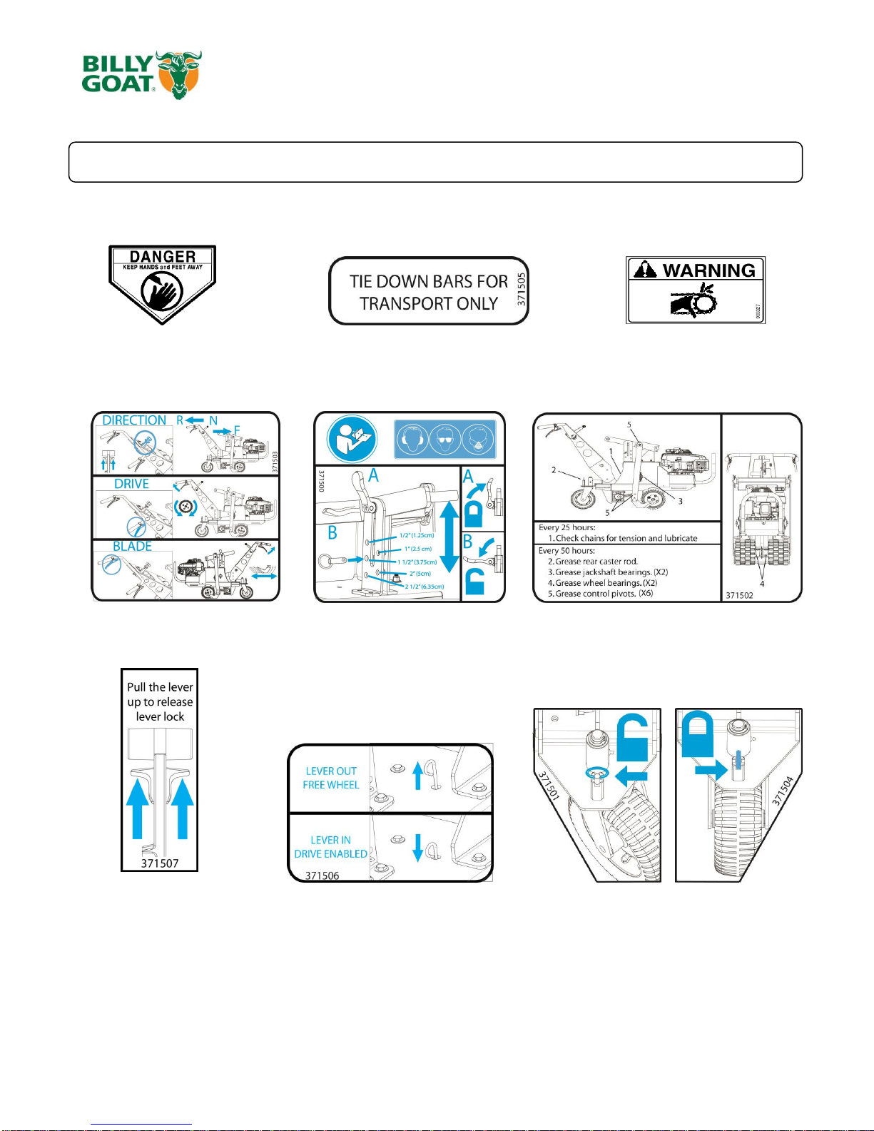
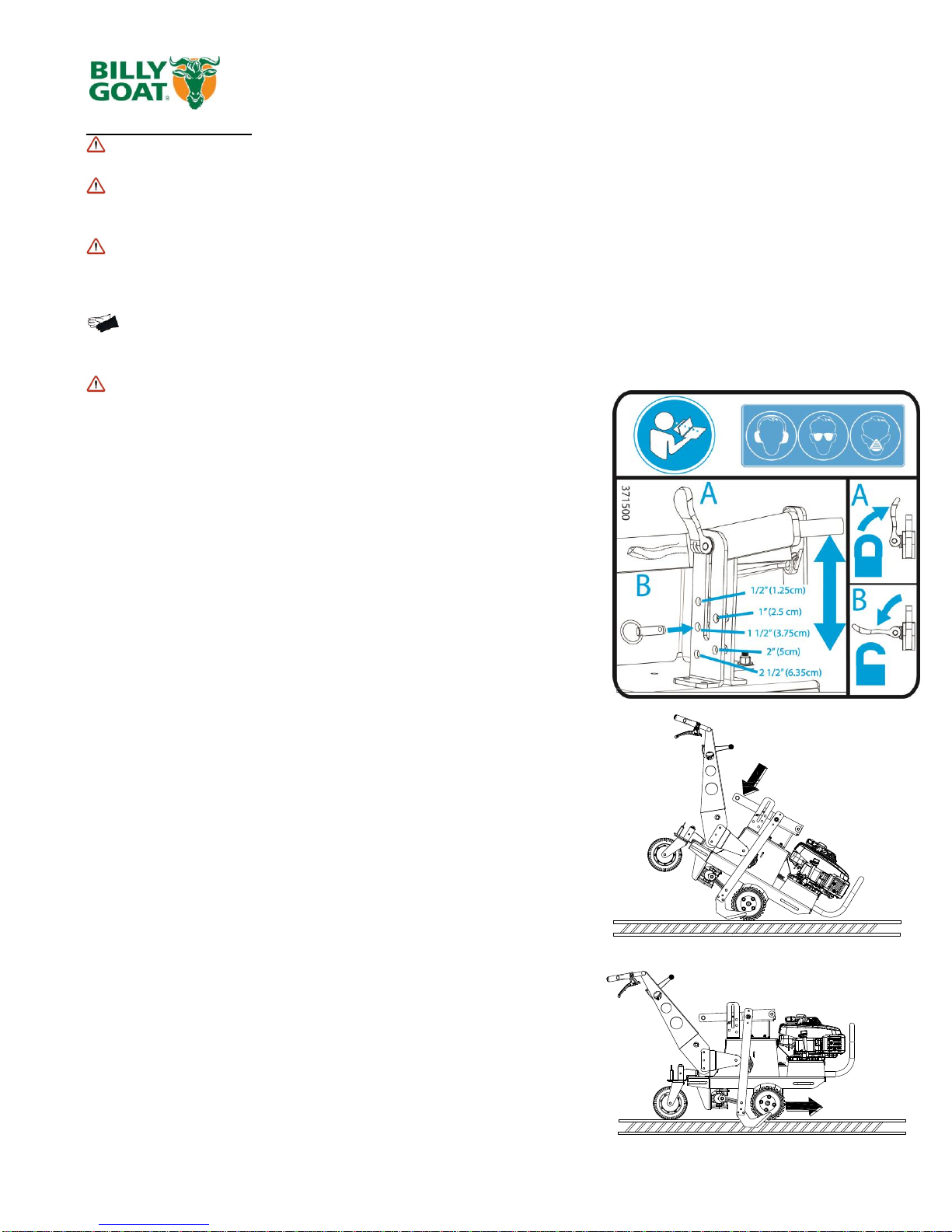
WARNING: DO NOT adjust cutting depth while machine is in
motion. Choose a cutting depth suitable for the type of terrain the
machine is to be used on. Cutting height is set using the removable
pin and placing it into the desired slot for depth. Then loosening the
locking lever to allow the arm to be raised or lowered. The arm should
be resting against the pin for the desired cutting height. Make sure to
engage the locking lever before blade operation.
1. Tilt the machine forward and select the proper cutting depth, make
sure to lock the blade height in place before cutting.
2. Engage the blade and engage the drive. This should pull the blade
into the ground.
3. To remove the blade from the ground make sure the machine and
blade are not in motion, then tilt forward and raise the height arm. Then,
engage the drive and blade again, this will allow the blade to cut out of
the sod.
CUTTING TIPS
1) Before commencing cutting operations, read the safety instructions
given in the previous sections.
2) At first the setting of a relatively shallow cutting depth is
recommended and then lowering it gradually according to working
conditions.
3) Engage the blade clutch only after having carried out the machine
switch on and gear engagement operations.

Part No 371508 Form No F091113A
11
SC180H Owner’s Manual
MAINTENANCE
PERIODIC MAINTENANCE
Periodic maintenance should be performed at the following intervals (disconnect spark plug during maintenance).:
Maintenance Operation
Every Use (daily)
Every 5 hrs or
(daily)
Every 25 Hrs
Every 50 Hrs
(Yearly)
Every 150
Hrs
Inspect for loose, worn or damaged parts.
Check for excessive vibration
Inspect belt for wear
Engine (See Engine Manual)
Grease pivot points
Sharpen Blade
Replace blade and traction belts
Note: Blade, and drive belts and chains are normal wear items. These should be inspected on a regular basis and
replaced if worn. Also see your Billy Goat Dealer for servicing your machine.
BELT REPLACEMENT
Switch off the engine and disconnect the spark plug wire before
carrying out any maintenance or repair work on the machine.
If a belt is worn or breaks it should be replaced as follows:
-remove the all of the metal guards (items 15, 16, 21 and 17) to allow
easier access to the pulleys and belts.
Note: see pages 14, 16 and 18 for part illustrations
BLADE BELT
1. Disconnect the spark plug, and then remove the guards.
2. Remove the master link on the drive chain (Item 133) to allow the
belt (item 132) to be slipped past.
3. Loosen the tension on the pulley (item 35) by loosening the nut
and bolt holding it to the base. Do not completely remove the nut and
bolt, as loosening it will allow the pulley to shift.
4. Walk the old belt off of the clutch (item 18) if necessary.
5. Replace with the new belt and reapply tension to it on the pulley
loosened in step 3 then tighten it. Do not put too much tension on the
belt as this will lead to premature wear.
6. Reinstall the chain onto the wheel drive by reinserting the master
link.
6. Reinstall the guards.
7. Check for proper operation.
DRIVE BELT
1. Follow steps 1-4 in the blade belt removal section. The blade belt will need to be removed in order to remove the drive belt.
2. Loosen the belt finger (119) on the idler arm (20) and remove the belt from the idler arm by lifting it over the idler pulley (39)
and arm.
3. The belt will be loose enough now to walk it off of the transmission pulley (32). Remove the belt from the transmission pulley.
4. Disconnect the clutch cable (110) and then remove the bolt (114) holding the clutch (18) to the engine shaft.
5. Lower the clutch (18) enough and slide the belt off of the clutch groove and replace the old worn belt with a new one. Make
sure it is sitting in the groove that the old one was removed from.
6. Reconnect the clutch back to the engine shaft. Make sure the anti-rotation bolt is in the small tube before reattaching. See
page 15 for proper torque for the clutch bolt.
7. Reinstall all removed parts in the reverse order that they were removed.
8. Check for proper operation.
133
131
132
130
ON UPPER GROOVE
OF CLUTCH
ON LOWER GROOVE
OF CLUTCH
See page 22 for parts illustration

Part No 371508 Form No F091113A
12
SC180H Owner’s Manual
CHECKING AND REPLACING THE BLADE
Always check the state of the blade (item 44) before commencing work. Do not forget to switch the engine off!
-Remove the sparkplug wire.
-During work operations if the blade strikes stones or stumps stop straightaway and make sure that it has not become bent
or broken. A damaged blade must be replaced.
-If the blade is very worn, cracked or bent, it may snap and project objects outwards, risking serious accident.
-Use heavy-duty work gloves to check or replace the blade to avoid risk of injury to hands.
-The blade fixing screws (item 81) and relative nuts (item 75) are also subject to wear. Always replace them at the same
time as the blade, using bolts and screws of the same strength and type.
-The blade wears more quickly on dry, sandy ground. In these conditions it should be replaced more frequently.
To remove the blade, proceed as follows:
1. Switch off the engine and disconnect the spark plug wire
2. Adjust the cutting height to maximum
3. Check the state of the blade.
Check that the blade is not cracked, bent, excessively worn or broken
4. When repair or check of blade is completed reattach spark plug
CHECKS
-Adjust the belt and cable control tension after the first few working hours to compensate initial loosening.
-Briefly operate all the machine's components to detect any abnormal noises or overheating.
-During the initial running in period avoid heavy-duty usage to encourage proper settling of the mechanical parts.
-Never neglect maintenance operations after work and carry out all pre-scribed checks regularly.
A) CABLE CONTROL ADJUSTMENT
To adjust the cables place the machine on flat ground, switch off the engine and disconnect the wire from the spark plug.
B1) BLADE AND DRIVE CONTROL CABLES
Adjustments to the tension on the cables are made by adjusting the barrel length located on the handle. By
extending the barrel more tension will be put on the cable. Make sure that you do not apply too much tension as
this will cause premature failure or cause the lever to engage when it is not wanted. Note: Apply lithium grease
to the slots on the drive levers where the cable sits to help extend cable life.
B2) SHIFTER CONTROL CABLE
Tension on the Shifter control cable (item 22) can be made by removing the rear cover and adjusting the barrel in or out
depending on the desired tension

Part No 371508 Form No F091113A
13
SC180H Owner’s Manual
Troubleshooting
When servicing engine refer to specific manufacturer’s engine owner's manual. All engine warranty is covered by
the specific engine manufacturer. If your engine requires warranty or other repair work contact your local servicing
engine dealer. When contacting a dealer for service it is a good idea to have your engine model number available
for reference (See table page 15). If you cannot locate a servicing dealer in your area you can contact the
manufacturer’s national service organization.
To reach: American Honda: 800-426-7701
WARRANTY CLAIM PROCEDURE
Should a BILLY GOAT ®machine fail due to a defect in material and/or workmanship, the owner should make a
warranty claim as follows:
The machine must be taken to the dealer from whom it was purchased or to an authorized Servicing BILLY
GOAT Dealer.
The owner must present the remaining half of the Warranty Registration Card, or, if this is not available, the
invoice or receipt.
The Warranty Claim will be completed by the authorized BILLY GOAT Dealer and submitted to their
respective BILLY GOAT Distributor for their territory Attention: Service Manager. Any parts replaced under
warranty must be tagged and retained for 90 days. The model number and serial number of the unit must
be stated in the Warranty Claim.
The distributor service manager will sign off on the claim and submit it to BILLY GOAT for consideration.
The Technical Service Department at BILLY GOAT will study the claim and may request parts to be
returned for examination. BILLY GOAT will notify their conclusions to the distributor service manager from
whom the claim was received.
The decision by the Technical Service Department at BILLY GOAT to approve or reject a Warranty Claim is
final and binding.
Make sure that the product is registered with Billy Goat. For online product registration go to www.billygoat.com
Problem Possible Cause Solution
Engine will not start.
Choke not on. Out of gasoline, bad or old gas. Spark plug wire
disconnected. Dirty air cleaner. Blade clutch is engaged
Check Gasoline. Check for spark with an approved
tester. Clean or replace air cleaner. Disengage the
Blade clutch lever.
Engine runs poorly
Spark plug wire loose. Carburetor out of adjustment. Water or
dirt in fuel system. Spark plug fouled, faulty or wrong gap
Sharpen or replace blade. Adjust carburetor (refer to
engine manual). Reset gap or replace spark plug (refer
to engine manual).
Belt slips
Belt tension inadequate. Too deep of a working depth. Belt
worn. Replace belt. Replace blade
Abnormal vibration. · Loose or out of balance blade. Bent blade. Loose engine bolts
Stop work immediately. Check blade mount and
balance. Replace damaged or bent blade if required.
Check engine mount.
Will not cut or has poor cutting
performance
Dull or bent Blade. Debris locked against blade. Engine running
at too low RPM. Sod is too dry.
Sharpen or replace blade. Remove debris. Check engine
RPM (refer to engine manual). Apply more water to
cutting area to loosen sod
Drive will not engage
Shifter in neutral. Out of adjustment drive cable. Broken drive
cable. Worn or broken belt.
Shift lever to desired direction and speed. Adjust drive
cable. Replace with new cable. Replace belt.
Drive will not release. Drive cable out of adjustment. Damaged drive lever. Adjust drive cable. Replace drive cable.
Engine is locked, will not pull over. Debris locked against blade. Damaged engine.
Remove debris. Refer to engine owner's manual.
Replace control cable.

Part No 371508 Form No F091113A
14
SC180H Owner’s Manual
PARTS DRAWING ENGINE ASSEMBLY
110 125
120
129128 122
124 127
121 126
123
1
2
35
18
10 11
19
102
83
60
76
57
53
59
58
63
87
75
76
76
72
63
75
85
46
61
113
112 114
46
116
64
117
95
76

Part No 371508 Form No F091113A
15
SC180H Owner’s Manual
PARTS LIST ENGINE ASSEMBLY
Item no. Part no. Description Qty
1371100 FRAME WA SC 1
2900615 ENGINE GXV 160 1
10 371400 TUBE BUMPER SC 1
11 371101 CASTER MOUNT WA 1
18 371264 CLUTCH SC 1
19 371102 CASTER RIG WA 1
35 520061 PULLEY IDLER 5L INSIDE 4" 1
46 371267 BELT FINGER 2
53 371206 WHEEL 8" X 3" HEAVY DUTY 1
57 8160005 NUT LOCK 1/2"-13 HEX 1
58 8041108 SCREWCAP 1/2"-13 X 4 3/4" HCS ZP 1
59 8172011 WASHER 1/2" SAE 1
60 520184 BUSHING FLANGE 1" OD X 3/4" ID 2
61 440153 WASHER 1.5" OD X .453 ID X .25 THK 1
63 8160003 NUT LOCK 3/8"-16 6
64 610363 GREASE ZERK 1
72 8041033 SCREWCAP 5/16"-18 X 2 1/4 GR 5 HCS ZP 4
75 8160002 NUT LOCK 5/16"-18 5
76 8171003 WASHER 5/16" FLAT 22
83 8041051 SCREWCAP 3/8"-16 X 1 1/4" HC ZP 2
85 8177012 LOCK WASHER 3/8" S/T MED 1
87 8024062 CARRIAGE BOLT 3/8"-16 X 2" ZP 1
95 8041031 SCREWCAP 5/16"-18 X 1 3/4" GR. 5 HCS ZP 1
102 520176 SNAP RING 1
110 371232 CABLE CLUTCH BLADE 1
112 900455 NUT WHIZ 1/4-20 WASH FACE 2
113 8041008 SCREWCAP 1/4"-20 X 1 1/2" HCS ZP 1
114 900344 SCREWCAP 3/8"-24 X 1 1/2" GR. 8 40-45 FT-LBS (54-61 N.m) 1
116 900162 KEY HI PRO 5/32 X 5/8" 1
117 400164 SCREWCAP 5/16"-24 X 1 " GR. 8 ZP W/PATCH 3
120 371510 LABEL BADGING SC 2
121 371503 LABEL INSTRUCTION DRIVE 1
122 371505 LABEL TIE DOWN 4
123 371501 LABEL CASTER LOCK LEFT 1
124 371506 LABEL DRIVE RELEASE SC 1
125 371502 LABEL GREASE POINTS SC 1
126 371504 LABEL CASTER LOCK RIGHT 1
127 371500 LABEL INSTRUCTION DEPTH 1
128 400424 LABEL DANGER 2
129 900327 LABEL WARNING GUARDS 4

Part No 371508 Form No F091113A
16
SC180H Owner’s Manual
PARTS DRAWING BLADE ASSEMBLY
NOTE: When
installing seals,
make sure spring
side of seal is away
from bearing
71
71
56
71
75
108
76
63
5455
55 54
51
107
75
88 76
85 52
83
76
64
57
56 56
71
81 70
56
105
77
75
69
56
57
80
90 68
71
85 88
101
100
89 57
56
64
51
56 76
83
63
61
44 38
30
14
33
32
42
24
13
31 5
4
6
6
194
137

Part No 371508 Form No F091113A
17
SC180H Owner’s Manual
PARTS LIST BLADE ASSEMBLY
Item no. Part no. Description Qty
1371100 FRAME WA 1
4371107 PIVOT DEPTH WA 1
5371106 BLADE DEPTH WA 1
6371108 BLADE ARM 2
13 371221 HEIGHT DEPTH BRACKET LH 1
14 371205 GEAR BOX "T" 2:1 REDUCTION 1
24 371219 LEVER CAM LOCK 1
30 371202 ECCENTRIC BLADE DRIVE 2
31 371259 SHAFT PIVOT DEPTH 1
32 371215 PULLEY 5" X 3/4" BORE 1
33 371208 TAB MOUNT SHIFT CABLE 1
38 371216 ARM BLADE DRIVE 2
42 371261 DETENT 1/2" DIA X 1" LG 1
44 371203 BLADE 18" WA 1
51 371247 BEARING SC 6
52 371260 ROD BEARING 1
54 371252 SEAL GREASE 12
55 371257 BUSHING BEARING SC 6
56 371237 WASHER PLASTIC 14
57 8160005 NUT LOCK 1/2"-13 HEX 4
61 440153 WASHER 1.5 OD X .453 ID X .25 2
63 8160003 NUT LOCK 3/8"-16 9
64 610363 GREASE ZERK 8
68 8041110 SCREWCAP 1/2"-13 X 2 3/4" GR 8 ZP 2
69 9201113 KEY 1/4" SQ X 1" 2
70 8041111 SCREWCAP 1/2"-13 X 3" GR 8 ZP 2
71 8171006 WASHER 1/2" USS 8
75 8160002 NUT LOCK 5/16"-18 8
76 8171003 WASHER 5/16" FLAT 32
77 9201072 KEY 3/16" SQ X 5/8" 1
80 371263 SHCS 5/16"-18 X 1" BLK OX 2
81 8041043 SCREWCAP 5/16"-18 X 1" GR 8 ZP 6
83 8041051 SCREWCAP 3/8"-16 X 1 1/4" HC ZP 8
85 8177012 LOCK WASHER 3/8" S/T MED 6
88 8041050 SCREWCAP 3/8"-16 X 1" HCS ZP 6
89 8024040 CARRIAGE BOLT 5/16"-18 X 1" GR. 5 HCS ZP 2
94 8177011 LOCK WASHER 5/16" S/T MED 1
100 8171004 WASHER 3/8" FC 2
101 8041026 SCREWCAP 5/16"-18 X 3/4" GR 5 HCS ZP 1
105 371222 CABLE CLAMP 4
107 371218 HEIGHT DEPTH BRACKET RH 1
108 360243 LANYARD PLASTIC 10" 1
137 790179 GRIP 1" X 4" 1

Part No 371508 Form No F091113A
18
SC180H Owner’s Manual
PARTS DRAWING HANDLE ASSEMBLY
TO ENGINE
TO TRANS
TO IDLER ARM
TO CLUTCH
50
135
134
1
3
7
7
23 28
27
22
21
16
15
17
48
103
104
63
8588
76 88
85
91
59
88
96
43
66
66
66
110
109
92
98
115
59
57

Part No 371508 Form No F091113A
19
SC180H Owner’s Manual
PARTS LIST HANDLE ASSEMBLY
Item no. Part no. Description Qty
1371100 FRAME WA 1
3371104 HANDLE SC WA 1
7371209 HANDLE BRACKET MOUNT 2
15 371207 GUARD FRONT 1
16 371242 GUARD MID RIGHT 1
17 371103 GUARD REAR WA 1
21 371233 GUARD MID LEFT 1
22 371204 SPEED CONTROL SC 1
23 351209 CONTROL LEVER DRIVE 2
27 371210 RUBBER HANDLE MOUNT 2
28 500267 GRIP 1" X 5.5" 2
43 891025 1/2" PRESSED STEEL HOUSING 2
48 500281 SWITCH TOGGLE 1
50 890132 PLUG TUBE 1" 2
57 8160005 NUT LOCK 1/2"-13 HEX 2
59 8172011 WASHER 1/2" SAE 2
63 8160003 NUT LOCK 3/8"-16 4
66 890359 SCREW SELF TAP 1/4"-20 X 5/8" HWH TYPE F 14
76 8171003 WASHER 5/16" FLAT 8
85 8177012 LOCK WASHER 3/8" S/T MED 4
88 8041050 SCREWCAP 3/8"-16 X 1" HCS ZP 8
91 8041097 SCREWCAP 1/2"-13 X 1 3/4 HCS ZP 2
92 8160001 NUT LOCK 1/4"-20 4
96 8041006 SCREWCAP 1/4"-20 X 1" HCS ZP 4
98 8171002 WASHER 1/4" FLAT 4
103 8059136 SCREW MACH #10-24 X 3/4 WF ZP 4
104 8155007 NUT LOCK #10-24 HEX 4
109 371220 CABLE CLUTCH WHEEL SC 1
110 371232 CABLE CLUTCH BLADE 1
115 360316 WIRE HARNESS 1
134 430303 LABEL PRODUCT LOGO CIRCLE LG 1
135 371507 LABEL SHIFTER CONTROL 1

Part No 371508 Form No F091113A
20
SC180H Owner’s Manual
PARTS DRAWING TRANSMISSION ASSEMBLY
109
136
136 136
119 1
8
9
20
39
26
29
41
40
37
25
34 36
12
58
83
85
61
69
57 59
66
69
63
76
73 73
89 75
78
79
62
63
76 86
75
93
75
76 49
45
67 95 76
47 74
63
94
93
73
76
111
100
63
22
118
74
Table of contents
Other Billy Goat Cutter manuals