Billyoh Rosette Assembly instructions

Billy Oh Rosette Green House – Assembly Hints and Tips
WARNING
Please refer to all safety notices in the greenhouse manual before assembling any of the sections
TOP TIPS
1. These instructions are generic for all models. Part numbers vary, please use this product in
accordance with your supplied instruction manual.
2. Please check you have the correct instructions. All parts should be labelled as follows:
Part A for the 12 8 greenhouse, Part B for the 10 8 greenhouse,
Part C for the 7.4 7.4 greenhouse, Part for the 8 6 greenhouse.
3. To ensure the base is level and square, the use of a spirit level is essential and diagonal
corner measurements must be taken and accurately correspond. Failure to achieve this will
result in the greenhouse frame being out of line and prevent accurate positioning of the
glazing panels.
4. When satisfied with the base section the frame should be erected with constant use of the
spirit level even though adjustments will be necessary as the work progresses.

5. When assembling the greenhouse assemble the screws and nuts lightly, once you are happy
with the construction these can be tightened completely. Do not over tighten.
6. On completion of the framework and before beginning the glazing, it is advisable to test the
square of each of the roof sections with one of the panels and likewise the side and other
sections.
7. When placing roof sections into the ridge make sure they are pushed as far up as possible
into the ridge section.
8. Ensure tape is used when commencing the glazing procedure. Without it the bottom of
panels will be vulnerable to high winds since the securing clips only attach to the sides of the
frame. Use tape at the top and bottom of the panel as a minimum guideline.
9. It may be necessary to nip the top corners of the roof panels with pliers to slip more easily
into the grooves, take care not to damage the panels as this would not be covered under
warranty.
10. The piece of tape for the top of the panels may be better fi ed from inside the greenhouse
as the recess is tight.
11. If the greenhouse is sited in an e posed location and/or is e posed to high winds,
improvisation for e tra protection may be considered. If so the following is recommended:
Drill 3 holes in the ridge section central to each of the roof panels. Then drill 3
corresponding holes in both gutters. Fi strong cord ( i.e. Clothes line ) through the holes
and make fast to further safeguard the roof panels. Give similar attention to the side and
rear panels. This time attach 2 cords horizontally and equally spaced. It is important to drill
the holes in the uprights as close as possible to the face of the panels. If these guidelines are
followed diligently, the panels cannot escape even if the clips are dislodged by gale force
conditions. (Please note this is a tip provided by a customer to provide additional protection
during strong winds. It is not guaranteed to prevent damage occurring during adverse
weather but merely a suggestion). (see Additional Customer Tips section)
12. To summarise, the erection of the BillyOh Rosette Greenhouse may in the beginning appear
a daunting task and the structure deceptively flimsy. However, with patience and
perseverance, the end result is worth all efforts and the finished article , remarkably
resilient.

Base Frame Assembly
Fig 1
Assemble the base frame as detailed in the instructions and secure using the bolts as above.
Place the nut and bolts into the top sections and secure loosely then lay the ne t sections on top
of the base as per Fig 1.
Corner Uprights
Offer the upright corner section to the base and slot the nut heads into the groove on the
upright, do this carefully. Once the nut heads are in the channel and the upright is in place the
nuts and bolts can be tightened. Do not over tighten.
Loosely insert nut and bolt
Uprights
Channels

Clips for Uprights
Each of the uprights has clips ( Part 35 ) on the inside which need to be used as shown to add
additional stability to the uprights.
Note how the corner is completed. The photo is taken
Inside the greenhouse and we are looking at the
Right hand corner. Insert triangle shaped piece before
adding supports.
Triangle Piece
Supports

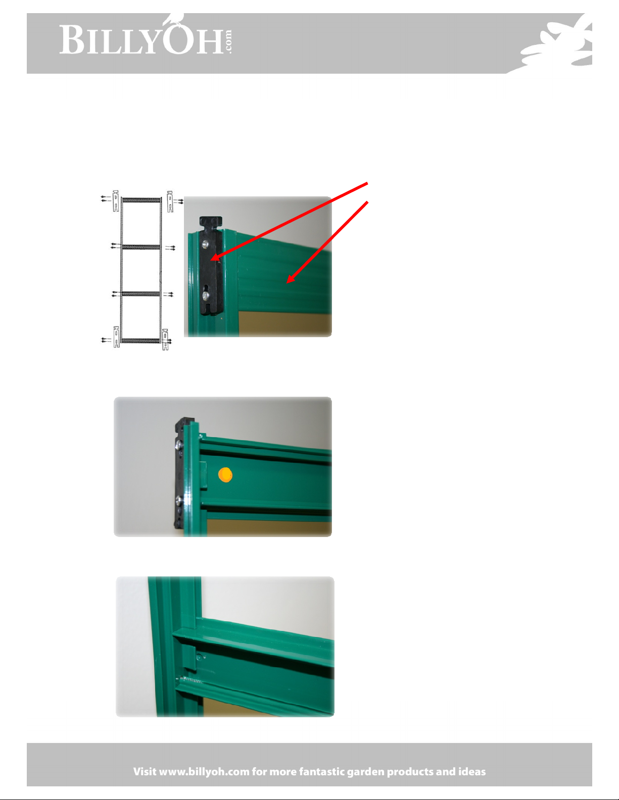
oor Runner Assembly
It is recommended to leave the fitting of the door runner ( Part #22
)until the rest of the greenhouse is complete. As a first stage when
building the main green house just place the nut and bolt in place on the
left and right side as per the following photo. These are the bolts that
the runner (part 22) slides onto at a later stage.
When you are ready to place the already
assembled doors onto the frame please take note of the following
which is for the right hand door.
Slide the runner over the left
hand bolt towards the right
hand bolt.
Then slide the first top door runner into the groove
Push the door runner further to the right and attach the
bolt into the groove and continue to push the runner over
to complete the fitting.
Place the remaining top door runner into the groove to
complete the door attachment process. Make sure you attach
the bottom grooves to the greenhouse base.
Once you have the runner in place with the doors, the last job
to do is to tighten the two top bolts.
oor Runner Corner Assembly
At first glance it appears from the instructions
that the fitting of the door rail assembly is complicated
because the door rail sits further forward than the
frame. To overcome this two L shaped clips are used in
conjunction with each other which allows the door
frame runner to be connected to the main greenhouse frame.
This is achieved as follows, place one L shape piece
onto the frame and use the nut and bolts to secure
then place the second L shaped piece on top of the
first one and bolt the two together, the second one can
then be bolted to the door frame runner.
Front View
Rear View

own Pipe Collector
The plastic down pipe connector slides between the gutter and the upright. Tip, you may need
to loosen the nut and bolts to assist in this then push the plastic connector in and re-tighten the
bolts.

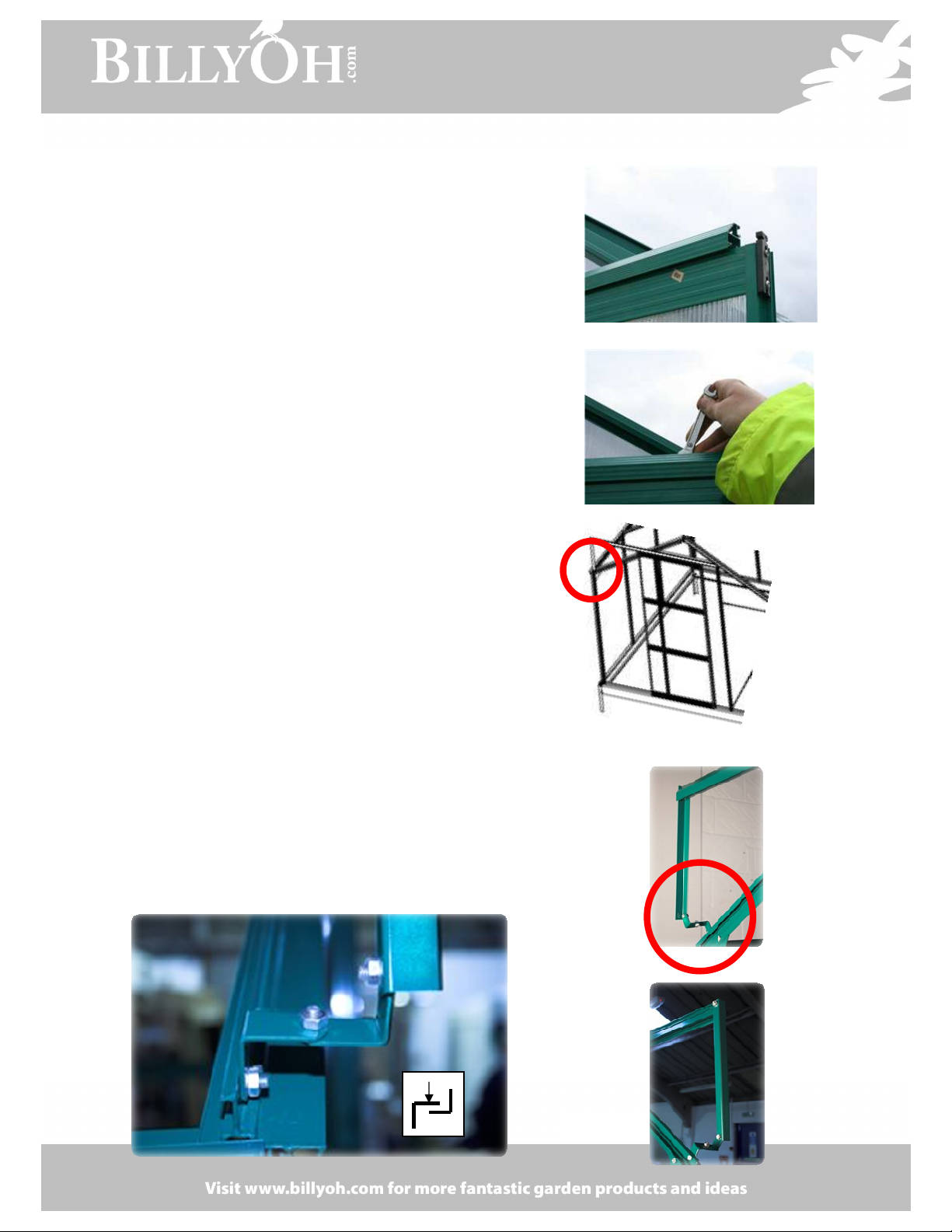
Opening Vent
Some greenhouses have one opening vent and the larger units have two. The assembly of them
is e actly the same. Assemble the frame of the opening vent as per the instructions.
Note the hole in the centre of the bottom section, this is for the opening vent handle.
Once the frame is assembled this needs to be slid into the ridge frame of the greenhouse. There is a
rounded top on the top edge of the opening vent and this needs to be slid into the opening on the
ridge. You may need to hold the opening vent at a sharp angle to allow this. Trial and error will show
you the correct method. Once in place slide the fame into position.
TOP

Please note that there will be gap
at the top of the opening vent. This
is normal and as it was designed to aid
the opening of the window.
View from outside
View from Inside

Tip for opening vent. If the vent falls through once it is installed, undue the nuts slightly on the coss
section and move up slightly until the bottom of the opening vent catches the centre cross member
to prevent the opening vent from falling through into the greenhouse.
Cross Member which can be moved into position
once the opening vent has been installed
Please make sure the cross member is correctly situated.
From the inside the groves should be at the top. This allows for the positioning of the window stay when
the window is open.
oor Frame Assembly – All Models
Figure 1 - Front
Figure 2 - Rear
Plastic Runner for
TOP
of door F
rame
Cross Member
Please note it is advisable to build the
door frame starting from the top, place
the cross member between the two
door frame edges and secure using the
plastic runners and the securing
screws. (figure 1&2) Do not tighten
until the plastic runner is in the correct
place. This will move up and down as
required.
Note how the cross members are
slotted into the frame edge (figure 3 ).
Please make sure that the plastic
runners are placed the correct way
around for the top of the frame and
the bottom of the frame. ( T shape for
top and U shape for the bottom ) Once
the cross member is secure at the top
of the frame place the glazing in the
frame and then place the ne t cross
member between the two frame edges
and secure with the screws provided
(figure 4). Please note the correct
fitting for the bottom plastic runner.
(figure 5).
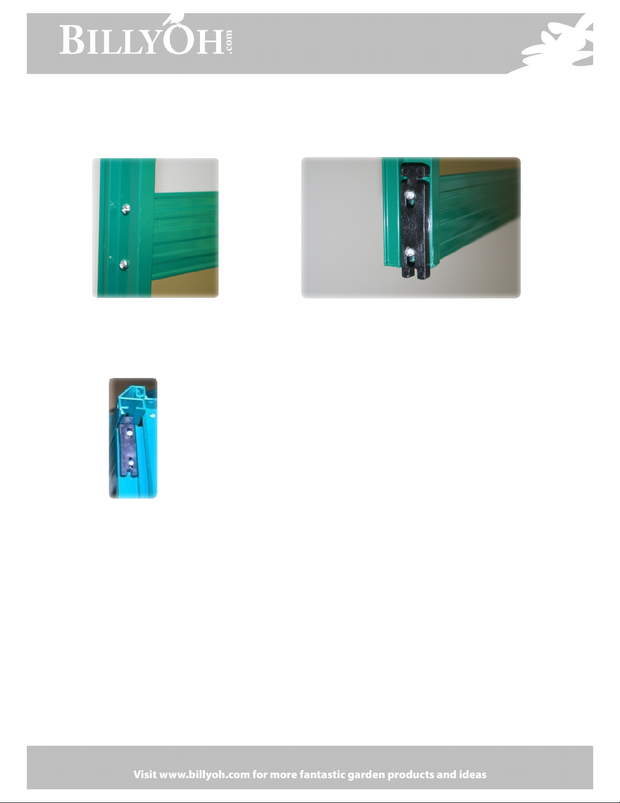
Figure 3 – Rear of Door
Figure 4 – Door Front Figure 5 – Bottom of Door
Figure 6
Please see figure 6 which
shows how door is placed
into the upper door frame.
Additional Tips Supplied by our Customers
(for information Only)
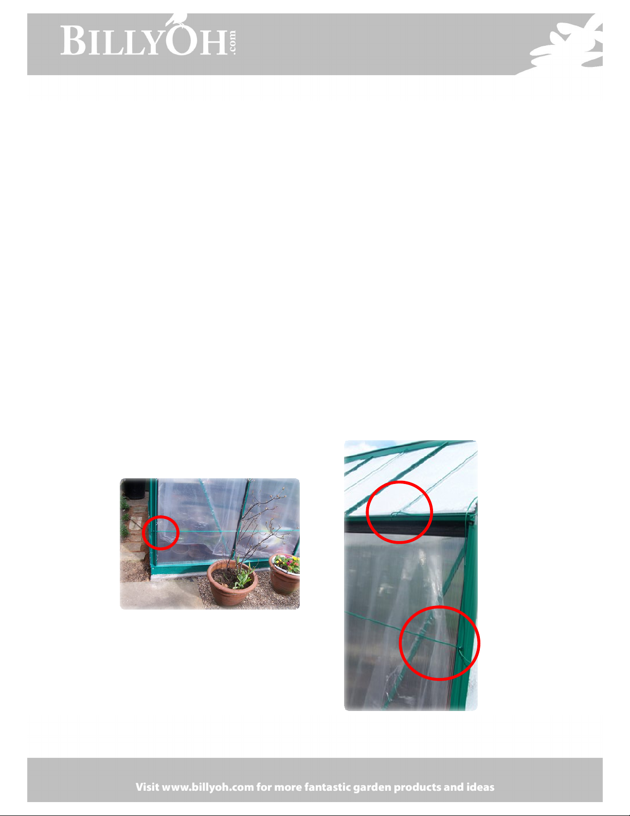
1. If the greenhouse is sited in an e posed location and/or is e posed to high winds,
improvisation for e tra protection may be considered. If so the following is recommended:
Drill 3 holes in the ridge section central to each of the roof panels. Then drill 3
corresponding holes in both gutters. Fi strong cord ( i.e. Clothes line ) through the holes
and make fast to further safeguard the roof panels. Give similar attention to the side and
rear panels. This time attach 2 cords horizontally and equally spaced. It is important to drill
the holes in the uprights as close as possible to the face of the panels. If these guidelines are
followed diligently, the panels cannot escape even if the clips are dislodged by gale force
conditions. (Please note this is a tip provided by a customer to provide additional protection
during strong winds. It is not guaranteed to prevent damage occurring during adverse
weather but merely a suggestion).
Customer Tip provided by Mr K Baldock www.brushclub.com
Table of contents
Popular Greenhouse Kit manuals by other brands


Alton
Alton Evolution Six LT instruction manual

Baux Industries
Baux Industries GROW KIT 2 ft x 4 ft Assembly instructions

GrowSpan
GrowSpan PB01670R4 manual

Vitavia
Vitavia VM0023-S Assembly instructions

Juliana
Juliana 05022016-MG Assembly instruction

GrowSpan
GrowSpan Twist-of-the-Wrist Assembly instructions