PNI SP6000 User manual

PNI GreenHouse SP6000
6KW MPPT
User manual …page 1
Manual de utilizare …pagina 27

-1-
1.Notes on this manual
1.1 Validity and information
This manual describe the assembly,installation,commissioning and maintenance of the
following SP Series inverter model: SP3600、SP4200、SP4600、SP5000、SP6000.The manual
and other documents must be stored in a convenient place and be available at all times.For
possible changes in this manual,we accepts no responsibilities to inform the users.
1.2 Target Group
This manual is for qualified personnel.Qualified personnel have received training and have
demonstrated skills and knowledge in the construction and operation of this device. Qualified
Personnel are trained to deal with the dangers and hazards involved in installing electric devices.
Any trouble in the installation,you can contact the supplier .
1.3 Symbols in this document
1.3.1 Warning in this document
A warning describes a hazard to equipment or personnel.It calls attention to a procedure or practice,
which, if not correctly performed or adhered to, could result in damage to or destruction of part or
all of the SP Series equipment and/or other equipment connected to the SP Series equipment or
personal injury.
Symbol
description
danger
DANGER indicates a hazardous situation which, if not avoided, will result in
death or serious injury.
warning
WARNING indicates a hazardous situation which, if not avoided, could result
in death or serious injury.
caution
CAUTION indicates a hazardous situation which, if not avoided, could result
in minor or moderate injury.
notice
NOTICE is used to address practices not related to personal injury.
information
Information that you must read and know to ensure optimal operation of the
system.

-2-
1.3.2 Markings on this product
Symbol desc
ripti
on
Electrical voltage!
Danger of high voltage and electric shock.
Risk of burns!
Danger of hot surface.
5min
Operation after 5 minutes
Signals danger due to electrical shock and indicates the time(5 minutes
)to allow after the inverter has been turned off and disconnected to
ensure safety in any installation operation .
CE mark.
The inverter complies with the requirements of the
applicable EC guidelines.
Point of connection for grounding protection
Direct Current (DC)
Alternating Current (AC)
The inverter has no transformer.
Read the manual
1.4 Glossary AC
Abbreviation for "Alternating Current"
DC
Abbreviation for "Direct Current"
Energy
Energy is measured in Wh (watt hours), kWh (kilowatt hours) or MWh (megawatt hours). The
energy is the accumulation of power over time. for example, your inverter operates at a constant
power of 5000 W for half an hour and then at a constant power of 2500 W for another half an
hour, it has fed 3750Wh of energy into the power distribution grid within that hour.
Power is measured in W (watts), kW (kilowatts) or MW (megawatts). Power is an instantaneous
value. It displays the power your inverter is currently feeding into the power distribution grid.
Power rate
Power rate is the radio of current power feeding into the power distribution grid and the
maximum power of the inverter that can feed into the power distribution grid.

-3-
Power Factor
Power factor is the ratio of real power and apparent power. They are identical only when current and
voltage are in phase and the power factor is 1.0. The power in an ac circuit is very seldom equal to
the direct product of the volts and amperes. In order to find the power of a single phase ac circuit the
product of volts and amperes must be multiplied by the power factor.
PV
Abbreviation for photovoltaic
wireless communication
The external wireless communication technology is a radio technology that allows the inverter and
other communication products to communicate with each other. The external wireless communication
does not require line of sight between the devices and it is selective purchasing.
2.Safety
2.1 Intended Use
The unit converts the DC current generated by the photovoltaic (PV) modules to grid- compliant
alternating current and performs single-phase feed-in into the electricity Grid.
SP3600M,SP4200M,SP4600M,SP5000M,SP6000M inverters are built
according to all required safety rules. Nevertheless, improper use may cause lethal hazards for the
operator or third parties, or may result in damage to the units and other property.
Principle of a PV plant with this SPXXXXM single-phase inverter
The inverter may only be operated with a permanent connection to the public power grid. The inverter
is not intended for mobile use. Any other or additional use is not considered the intended use. The
manufacturer/supplier is not liable for damage caused by such unintended use. Damage caused by
such unintended use is at the sole risk of the operator.
PV modules Capacitive Discharge Currents
PV modules with large capacities relative to earth, such as thin-film PV modules with cells on a metallic
substrate, may only be used if their coupling capacity does not exceed 470nF. During feed-in operation,
a leakage current flows from the cells to earth, the size of which depends on the manner in which the
PV modules are installed (e.g. foil on metal roof) and on the weather (rain, snow). This "normal"
leakage current may not exceed 50mA due to the fact that the inverter would otherwise automatically
disconnect from the electricity grid as a protective measure.
INVERTER
Energy meter
PV modules
DC load circuit
breaker
AC load circuit
breaker
Utility grid

-4-
2.2 Qualification of skilled person
This grid-tied inverter system operates only when properly connected to the AC -distribution network.
Before connecting the SP Series to the power distribution grid, contact the local power distribution grid
company. This connection must be made only by qualified technical personnel to connect, and only
after receiving appropriate approvals, as required by the local authority having jurisdiction.
2.3 Safety instruction
The SP Series Inverters is designed and tested according to international safety requirements; however,
certain safety precautions must be observed when installing and operating this inverter. Read and follow
all instructions, cautions and warnings in this installation manual. Any questions, please contact the
supplier .
2.4 Assembly Warnings
warning
Before installation, inspect the unit to ensure absence of any transport or handling
damage, which could affect insulation integrity or safety clearances; otherwise it
could result in safety hazards.
Assemble each inverter the instructions in this manual. Be Careful when choosing
installation location and according to specified cooling requirements. Unauthorized
remove the necessary protections, improper use, incorrect installation and operation
may result the serious safety and shock hazards or equipment damage.
In order to minimize the potential of a shock hazard due to hazardous voltages, cover
the entire solar array with dark material prior to connecting the array to any
equipment.
caution
Grounding the PV modules:The SP Series is a high frequency inverter(without
transformer). That is why it has no galvanic separation. Do not ground the DC circuits
of the PV modules when connected to the SP Series. Only ground the mounting frame
of the PV modules.If you connect grounded PV modules to the SP Series, that will
show error message "PV ISO Low".
Follow the local requirements for grounding the PV modules and the PV generator.
We recommend connecting the generator frame and other electrically conductive
surfaces in a manner which ensures continuous conduction with ground in order to
have optimal protection of the system and personnel.
2.5 Electrical Connection Warnings
The components in the inverter are mobilizable. Touching mobilizable
components can result in serious injury or death.
Do not open the inverter except the wire box by qualified persons.
Electrical installation, repairs and conversions may only be carried out by
electrically qualified persons.
Do not touch damaged inverter.
Danger to life due to high voltages in the inverter.
There has residual voltage in the inverter. The inverter takes 20 minutes to
discharge.
Wait 20 minutes before you open the wire box.
Persons with limited physical or mental abilities may only work with the SP Series
inverter following proper instruction and under constant supervision. Children are
forbidden to play with the SP Series inverter. Must keep the SP Series inverter away
from children.
danger

warning
Make all electrical connections (e.g. conductor termination, fuses, PE connection, etc.)
in accordance with prevailing regulations. When working with the inverter, adhere to
all prevailing safety regulations to minimize risk of accidents.
Systems with inverters typically require additional control (e.g., switches,
disconnects) or protective devices (e.g., fusing circuit breakers) depending on the
prevailing safety rules.
caution
The SP Series Inverter converts DC Current from PV generator into AC current. The
inverter is suitable for mounting indoors and outdoors.
You can use the AC current generated as follows:
2.6 Operation Warnings
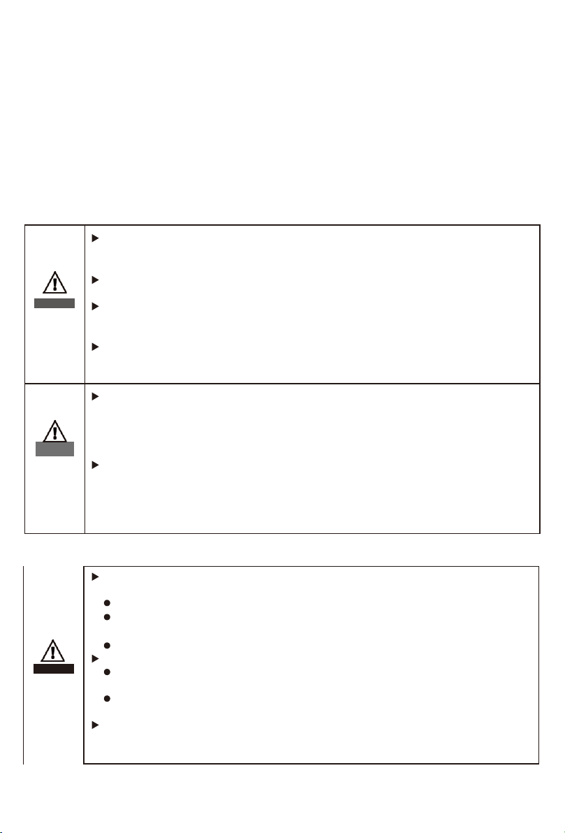
warning
Make sure all covers and doors closed and secure during operation..
Although designed meeting all safety requirements, some parts and surfaces of Inverter
are still hot during operation. To reduce the risk of injury, do not touch the heat sink at
the back of the PV-Inverter or nearby surfaces while Inverter is operating.
Incorrect sizing of the PV plant may result in voltages which could destroy the
inverter. The inverter display will read the error message “PV-Overvoltage!”
Switch the rotary DC Disconnect to the Off position immediately.
Contact installer.
caution
All operations regarding transport, installation and start-up, including
maintenance must be operated by qualified, trained personnel and in
compliance with all prevailing codes and regulations.
Anytime the inverter has been disconnected from the power network, please be much
careful as some components can retain charge sufficient to create a shock hazard; to
minimize occurrence of such conditions, please comply with all corresponding safety
symbols and precautions and present on the unit and in this manual.
In particular cases, there may still be interference for the specified application area
despite maintaining standardized emission limit values (e.g. when sensitive equipment
is located at the setup location or when the setup location is near radio or television
receivers).In this case, the operator is obliged to take proper action to rectify the
situation.
Do not stay closer than 20 cm to the inverter for any time.
-5-
House grid
Energy flows into the house grid. The consumers connected, for
example, household devices or lighting, consume the energy.
The energy left over is fed into the public grid. When the SP
Series is not generating any energy, e.g., at night, the
consumers which are connected are supplied by the public
grid.The SP Series does not have its own energy meter. When
energy is fed into the public grid, the energy meter spins
backwards.
Public grid
Energy is fed directly into the public grid. The SP Series is
connected to a separate energy meter. The energy produced is
compensated at a rate from the electric power company

-6-
PV Grid Inverter
3. Product description
3.1 SP Series Overview
LED
DC switch AC Output
PV Input
information
The SP Series series inverter can choose whether to bring a DC
switch depending on customers' need.
Symbol on the inverter
Symbol
Description
Explanation
Inverter status symbol Indicates inverter operation status
3.2 Inverter label
The inverter can be identified by the label on the left side of inverter.It shows the Products
type,the inverter specific features and the parameter on the label.
Model Name
SP****M
DC max. voltage ***V
MPPT voltage range
**-***V
DC max. current
**A/**A
AC nominal voltage ***V
Grid frequency 50Hz
Rated AC power ****W
Max. AC out apparent power ****VA
Max. AC current ***A
Power factor range 0.95c-0.95i
Protection degree IP65
Protective class Class I
Operation ambient
temperature -25℃~+60℃

-7-
Please kindly check the inverter detail specifications as below:
Model Name
SP3600
SP4200
SP4600
SP5000
SP6000
Max input DC voltage
550V
MPPT voltage range
100V
-
550V
DC max.current
11A/11A
AC nominal voltage
230V
Grid frequency
50HZ
Rated AC power
3600W
4200W
4600W
5000W
6000W
Max.AC out
apparent power 3600VA 4200VA 4600VA 5000VA 6000VA
Max.AC current
16
.
4A
19
.
1A
21A
22
.
8A
27.3A
Communications Ports
USB
Protective class
Class I
Protection degree
IP65
Operation ambient
temperature
-25℃-60℃
3.3 Inverter Dimensions
Dimensions and weight:
Model
Height
(
H
)
Width
(
W
)
Depth
(
D
)
Weight
SP6000M
412mm 16.2inch
355mm 14inch
201mm 7.9inch
16kg
3.4 Storage environment of Inverter
If you want to storage the inverter in the warehouse, Please select a suitable place to storage. The
inverter must be stored in original package and please keep stored in a dry environment The storage
temperature should be always between -25o Cand +60o C. And the storage
relative humidity should be always between 0 and 95%.(Recommend storage environment)
If there are a batch of inverters need to be stored, the maximum layers for original carton is four.
After long term storage, The local installer or Service centre should perform a
comprehensive test before installation the inverter&system;
3.5 Advantage of the inverter:
Wide input voltage range from 70--550Vdc
IP65 protection degree
Integrated DC switch
DSP controller
Fanless integrated cooling technology
Multi MPP controller
Easy installation

-8-
4.Installation
4.1 Installation step
4.2 Unpacking and inspection
After opening the package, please check the contents of the box. It should contain the following, Please
check all of the accessories in carton. If anything missing,please contact your dealer at once.
Shows the components and mechanical parts that should be delivered
NO.
Pictures
description
Quantity
1
SP Series
1PCS
2
Mounting frame
1PCS
3
PV+ input terminal
2PCS
4
PV- input terminal
2PCS
5
Metal terminals securedto PV+ input
power cables
2PCS
6
Metal terminals secured to PV- input
powercables
2PCS
7
Blasting screws
4PCS
8
M5 cross screws 2PCS
End Install
inverter
frame
Install
Mounting
Take out
Inverter
Start Check
accessory
prepare
tool
choose installtion
place

-9-
9
Output terminals 1PCS
10
Certificate 1PCS
11
Manual 1PCS
4.3 Tools
NO. Tool Model Function
1
Hammer drill
Recommend drill dia.
6mm
To drill holes on the wall
2
Removal tool Remove PV terminal
3
Wire stripper Strip wire
4
Wrench
Turn the screw to connect rear
panel with inverter
5
Crimping tools To crimp power cables
4.4 Selecting the installation location
This is guidance for installer to choose a suitable installation location, to avoid potential
damages to device and operators.
The installation location must be suitable for the inverter's weight and dimensions for a long period
time.
Select the installation location so that the status display can be easily viewed.
Do not install the inverter on structures constructed of flammable or thermolabile materials.
Never install the inverter in environment of little or no air flow, nor dust environment. That may
derate the efficiency of the cooling fan of the inverter.
The Ingress Protection rate is IP65 which means the inverter can be installed outdoors and
indoors.
The humidity of the installation location should be 0~95% without condensation. The
installation location must be freely and safely to get at all times.
Vertically installation and make sure the connection of inverter must be downwards. Never install
horizontal and avoids forward and sideways tilt.

max 15°
Be sure that the inverter is out of the children’s reach.
Don’t put any things on the inverter. Do not cover the inverter.
Do not install the inverter near television antenna or any other antennas and antenna cables.
Inverter requires adequate cooling space. Providing better ventilation for the inverter to ensure
the heat escape adequately. The ambient temperature should be below 40°C to ensure optimum
operation.
Do not expose the inverter to direct sunlight, as this can cause excessive heating and thus power
reduction.
Observe the Min. clearances to walls, other inverters, or objects as shown in the diagram:
50cm 50cm
Ambient dimensions of one inverter
Ambient dimensions of series inverters
-10-
80cm
Direction
Min. clearance (cm)
above
80
below 50
sides
50
front 30
50cm

There must be sufficient clearance between the individual inverters to ensure that the cooling
air of the adjacent inverter is not taken in.
If necessary, increase the clearance spaces and make sure there is enough fresh air supply to
ensure sufficient cooling of the inverters.
The inverter can’t install to solarization,drench,firn location. We suggest that the inverters should
be installed at the location with some cover or protection.
Please make sure the inverter is installed at the right place.The inverter can’t install close to trunk
。
4.5 Mounting the Inverter
4.5.1 Mounting the Inverter with bracket
danger
In order to avoid electrical shock or other injury, inspect existing electronic or
plumbing installations before drilling holes.
lUsing the mounting frame as a template, drill 4 holes as illustrated in image.
314,00
208,00
Φ10,00
160,00 200,00
(图a) (图b)
-11-
OK OK
NO OK
OK OK
NO
N
O

step:
1.Align the mounting frame with hole positions, fix the mounting frame on the wall by
tightening the expansion bolt withthe nuts.
2.Hook the inverter to the rear panel. Using an M5 screw to secure the inverter to the
mounting frame to ensure safety.
3.make sure all screws install inplace.
5.Electrical connection
5.1 safety
Danger to life due to lethal voltages!
High voltages which may cause electric shocks are present in the
conductive parts of the inverter. Prior to performing any work on the
inverter, disconnect the inverter on the AC and DC sides
warning
Danger of damage to electronic components due to electrostatic
discharge.
Take appropriate ESD precautions when replacing and installing the
inverter.
-12-

5.2 Wiring AC Output
warning
You must install a separate single-phase circuit-breaker or other load
disconnection unit for each inverter in order to ensure that the inverter can
be safely disconnected under load.
NOTE: The inveter have the residual current detect and protect function, if you
have device the AC breaker have the residual current detect function,you must
choice breaker the rating residual current more than 300mA.
notice
When using inverter with VDE-AR-N 4105, because the inverter's displacement
factor adjust function had to accorded to VDE-AR-N 4105,the PV-inverter
system total capacity cannot be over 13.8KVA. When using inverter with CEI 0-
21: if the inverter system total capacity more than 3KW and up to 11.08KW,the
displacement factor is adjustable between 0.95 leading to 0.95 lagging ,and
not need the external SPI.if the inverter system total capacity more than
11.08KW,,the displacement factor is adjustable between 0.9leading to 0.9
lagging ,and need the external SPI.
You must install a separate single-phase circuit-breaker or other load disconnection unit for each
inverter in order to ensure that the inverter can be safely disconnected under load.
We suggest you choice the AC breaker rating current in this table:
SP6000 42A/230V
We recommend electrical connection as below
The AC wiring step
1. The grid connection is contains using 3 conductors (L, N, and PE).
-13-
INVERTER
Energy meter
PV modules
DC load circuit
breaker
AC load circuit
breaker
Utility grid

Click!
Click!
2. Remove the parts of the AC connection plug from the accessory bag.Prepare the pressure
screw, sealing ring, threaded sleeve over the AC cable
socket element threaded sleeve sealing ring pressure screw
3. Insert the stripped and bared conductors L,N,PE into the screw terminals with sign L,N,PE on
the socket element and tighten the screws firmly.
notice
Note that the polarity of the connection line matches the terminal tag to avoid
incorrect connection.
4. Push the threaded sleeve into the socket element; screw the pressure screw tightly onto the
threaded sleeve;
-14-

5. Finally, insert the AC connection plug into the AC connection receptacle on the inverter.
Lock the housing
Wire suggestion
length:
Unlock the housing
Conductor cross
section
Max. cable length
SP3600
SP4200
SP4600
SP5000
SP6000
5.2mm² 10AWG
40m 34m 31m 28m 24m
6.6mm² 9AWG
50m
43m
39m
36m
30m
5.3 Protect the earth
If the installation is required, the grounding terminal may be used to connect to the secondary
protective earthing terminal or as an equipotential connection, as shown in the figure below.
5.4 Wiring DC Input
5.4.1 Connecting DC Input Power Cables
Step1 Remove cable glands from the positive and negative connectors.
Step2 Take out metal terminals from accessory package ,Wiring as illustrated in image.
Step3 Insert the positive and negative power cables into corresponding cable glands.
Step4 Insert the stripped positive and negative power cables into the positive and negative
metal terminals respectively and crimp them using a clamping tool. Ensure that the cables are
crimped until they cannot be pulled out by force less than 400 N, as shown in image.
L2=8-10mm
L1
L2=8-10mm
L1

-16-
Step 5 Insert the positive and negative connectors into corresponding DC input terminals of the
SP Series until you hear a "click" sound.
5.4.2 Conditions for DC Connection
The SP0 single-phase inverter has 2 independent input : input A & input B
The diagram drawing of DC side is shown as below, notice that the connectors are in paired (male
and female connectors). The connectors for PV arrays and inverters are H4 (yunfan) connectors;
Suggestions for the PV modules of the connected strings:
Same type
Same quantity of PV modules connected in series
positicve and negative connectors
SP Series DC input terminals
MPPT2
Input2
A
MPPT1
Input1
String
input
String
input

-17-
If the inverter is not equipped with a DC switch but this is mandatory in the
country of installation, install an external DC switch.
The following limit values at the DC input of the inverter must not be exceeded:
Model name Max.current input A Max.current input B
SP6000M 11A 11A
5.4.3 Connecting the PV Array (DC input)
danger
Before connecting the PV array, ensure that the DC switch and AC breaker are
disconnect from the inverter. NEVER connect or disconnect the DC connectors
under load.
Make sure the maximum open circuit voltage(Voc) of each PV string is
less than 550Vdc.
Check the design of the PV plant. The Max. open circuit voltage, which can
occur at solar panels temperature of -10℃, must not exceed the Max. input
voltage of the inverter.
warning
Improper operation during the wiring process can cause fatal injury to
operator or unrecoverable damage to the inverter. Only qualified personnel
can perform the wiring work.
5.5 Grounding the inverter
The inverter must be connected to the AC grounding conductor of the power distribution grid via the
ground terminal (PE) .
warning
Because of the transformerless design, the DC positive pole and DC
negative pole of PV arrays are not permitted to be grounded.
caution

-18-
6.Commissioning
6.1 LED display
Operation normal
(Green)
Error display
(Red)
WiFi communication
(Blue)
Green LED
Continuous light
Normal status
Flicker Waiting status
Blue LED Flicker Wifi normal communication
Red LED Continuous light
Fault status
Flicker
Program of procedure or give an alarm
6.2 WIFI Communication Connection
Please refer to the Wi-Fi Plug14 Quick Installation Guideline.

-19-
7.Start-Up and shut down the inverter
7.1 Start-Up the inverter
1. Connect the AC breaker of theinverter.
2. Turn on the dc switch, and the inverter will start automatically when the input voltage is
higher than 100V.
7.2 Turn-off the Inverter
danger
Do not disconnect the DC connectors under load.
Turn –off the inverter step:
Disconect the line circuit breaker from single-phases grid and prevent it from being
reactivated.
Turn off the dc switch.
Check the inverter operating status.
Waiting until LED, display have go out, the inverter is shut down.
8. Maintenance and Cleaning
8.1 Checking Heat Dissipation
If the inverter regularly reduces its output power due to high temperature, please improve the heat
dissipation condition. Maybe you need to clean the heat sink.
8.2 Cleaning the Inverter
If the inverter is dirty, turn-off the AC breaker and DC switch ,waiting the inverter shut down
,then clean the enclosure lid, the display, and the LEDs using only a wet cloth. Do not use any
cleaning agents (e.g. solvents or abrasives).
8.3 Checking the DC Disconnect
Check for externally visible damage and discoloration of the DC Disconnect and the cables at regular
intervals.If there is any visible damage to the DC Disconnect, or visible discoloration or damage to the
cables, contact the installer.
Once a year, turn the rotary switch of the DC Disconnect from the On position to the Off position 5 times
in succession. This cleans the contacts of the rotary switch and prolongs the electrical endurance of the
DC Disconnect.contacts of the rotary switch and prolongs the electrical endurance of the DC Disconnect.
9.Trouble shooting
Sometimes, the PV inverter does not work normally, we recommend the following solutions for
common troubleshooting. The following table can help the technician to understand the problem and
take action.
This manual suits for next models
3
Table of contents
Languages: