BILOXXI RHP25 User manual

Instruction manual
Hand pallet truck
RHP25
t
Original instructions
(IM)237‐000413_RHP25_GB-IM_V4_150626.indd 1 7/3/15 17:09

-2-
Dear Customer,
Congratulations on your purchase of this BILOXXI product.
Please take a few minutes before starting operation of the appliance and read the
following operating instructions.
Many thanks.
MCC Trading International GmbH
Schlüterstr. 5
40235 Düsseldorf
METRO-Habib Cash & Carry Pakistan (Pvt) Limited
Thokar Niaz Baig, Multan Road
Lahore 53700, Pakistan.
For Customer Feedback:
Call: 111-786-622
E-mail: feedback@metro.pk
Visit us: www.metro.pk
Made in Vietnam
Net weight: 64 kg
METRO Cash & Carry India Private Limited,
No. 26/3, Industrial Suburbs, Ward No. 9
A Block, Subramanyanagar,
BANGALORE - 560 055
D&D Technologies Co.,Ltd
Lot 105-106 Linh Trung III IP & EPZ, Trang Bang
Tay Ninh, Vietnam
Net weight: 64 kg
For Feedback / Suggestion & Complaints:
Customer Care Executive,
P.O. Box No. 5600, Bangalore 560 055,
Customer Care NO.: 18602662010 (Toll Free)
(IM)237‐000413_RHP25_GB-IM_V4_150626.indd 2 7/3/15 17:09

-3-
Contents
1. Intended use ......................................................................................................................3
2. Technical data ...................................................................................................................3
3. Symbols and abbreviations ...........................................................................................4
4. Safety warnings ................................................................................................................6
5. Parts description ...............................................................................................................8
6. Scope of delivery ........................................................................................................... 10
7. Before use ....................................................................................................................... 10
8. Operation ........................................................................................................................ 12
9. Troubleshooting ............................................................................................................. 13
10. Cleaning, maintenance and repair ............................................................................ 15
11. Storage and transportation ......................................................................................... 17
12. Hydraulic diagram ......................................................................................................... 18
13. Disposal ........................................................................................................................... 18
14. Warranty .......................................................................................................................... 19
1. Intended use
This pallet hand truck is designed for lifting and transporting heavy objects up to
the rated load on a suitable carrier such as industrial pallets.
It is not intended for any commercial or industrial use.
Do not use it for other purposes. Any other use might lead to damage or personal
injury.
2. Technical data
General
Load capacity 2500 kg
Net weight 64 kg
Max. lifting height 200 mm
Min. lifting height 85 mm
Till height 1210 mm
Overall length 1480 mm
Fork dimensions 160 x 50 x 1150 mm
(IM)237‐000413_RHP25_GB-IM_V4_150626.indd 3 7/3/15 17:09
-4-
2. Technical data
Wheel type and size (front) Ø 180 x 50 mm / Polyurethane
Wheel type and size (rear) Ø 80 x 70 mm / Polyurethane
Operating temperatures 5°C to 40°C
Minimum operating lighting 50 lx
3. Symbols and abbreviations
On the product, the rating label and within these instructions you will find among
others the following symbols and abbreviations. Familiarise yourself with them to
reduce hazards like personal injuries and damage to property.
kg kilogram
mm millimetre
°C temperature in celsius
lx illuminance in lux
cSt viscosity in centistokes
Lot. no. batch number
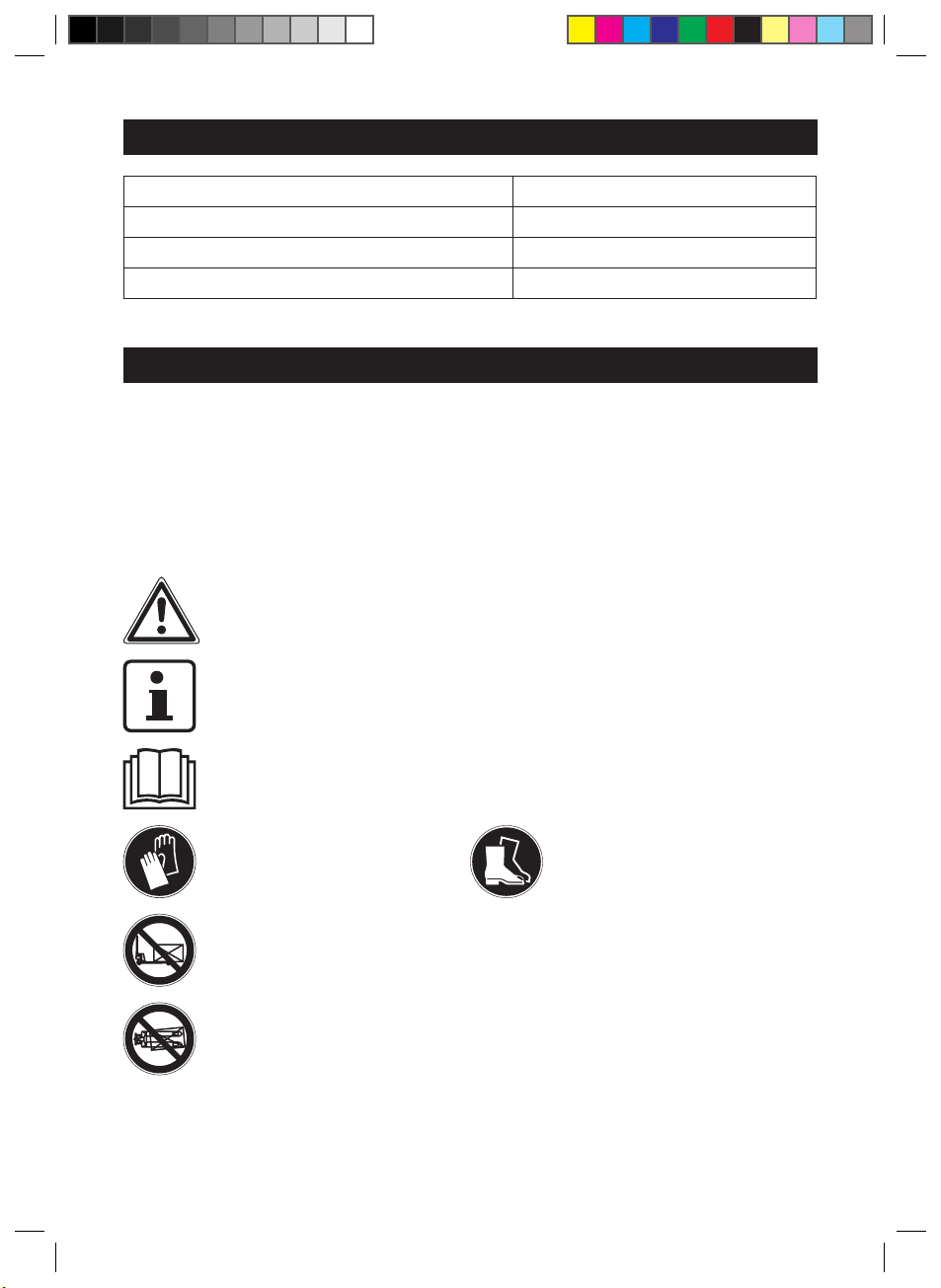
Warning symbol.
This symbol indicates additional information and explanations about
the product and its use.
Read the instruction manual before operation.
Wear protective gloves. Wear sturdy footwear.
Do not place load only partially on the forks. Always use the entire
loading area.
Do not place loads transversely.
(IM)237‐000413_RHP25_GB-IM_V4_150626.indd 4 7/3/15 17:09

-5-
3. Symbols and abbreviations
Do not place loads unilateral.
Do not place your feet under the forks, especially when lowering the
forks.
Do not put your foot in front of rolling wheel, as you could suffer
injury.
Do not lift or carry persons, as they could fall down and suffer severe
injuries.
Do not use the product on a slope or inclined surface, as it may
become uncontrollable and create danger.
Do not overhang the product at loading docks. Use extreme caution
when approaching loading docks.
Do not allow another person than the operator to stand in front of or
behind the product, when it is moving or lifting/lowering.
Warning! Danger of crushing of fingers or hands!
Indoor use only.
CE stands for “Conformité Européenne” which means “Conformity
with EU directives”. With the CE marking the manufacturer confirms
that this product corresponds to the applicable European directives.
(IM)237‐000413_RHP25_GB-IM_V4_150626.indd 5 7/3/15 17:09

-6-
4. Safety warnings
1. The operator / the operating company has to ensure the correct usage and has
to ensure that this product is used only by staff, who is trained and authorised
to use this product.
2. The product must be only used by one person at a time and he has to ensure
the necessary clearance to manoeuvre the product safely.
3. Keep the operating area clear from all by-standers, when moving, lifting and
lowering the product.
4. The product must not be used to transport humans or live animals.
5. The product must not be used by children.
6. The product must not be overloaded. The maximum load is 2500 kg.
7. The product must not be used in applications, where the danger exists the
maximum load is exceeded.
8. Distribute the load as evenly as possible.
9. Do not pull the product with vehicles.
10. Keep the centre of gravity as low as possible.
11. Stack loads from bottom to top, heaviest to lightest.
12. Always observe the load and watch out for goods about to drop. In this case,
stop immediately and rearrange the load.
13. Reduce the load correspondingly if the product is to be used on angled surfaces
e.g. ramps.
14. When moving the product over a slightly inclined surface (< 2°), the forks must
be empty.
15. The product must not be used on inclining paths (> 2°), as the danger of loss
of control exists.
16. Use both hands to push the product loaded and unloaded and move it slow
and evenly.
17. The required force needed to handle the product is varying with weight of the
load, the conditions of flooring and the product itself. Consider the frequency
of use under load.
18. Use only spare parts or accessories recommended by the manufacturer.
19. Do not modify the product or install accessory equipment.
20. Do not use the product in wet or extremely humid environments.
21. Do not use the product in explosive atmospheres.
22. Always wear personal protective equipment.
23. Never reach inside the lifting mechanism or below the forks.
24. Be aware that wind can affect the stability and handling of the product,
particularly when transporting loads with large surface areas.
25. Never leave the loaded product unattended.
26. The product must be used on substantially firm, smooth, level and prepared
surfaces.
(IM)237‐000413_RHP25_GB-IM_V4_150626.indd 6 7/3/15 17:09

-7-
4. Safety warnings
27. Regularly check the product according to the instructions given within this
manual.
28. The product must be used, maintained and repaired in accordance with
manufacturer’s recommendations given within this manual.
NOTE: No modifications or alterations to this product which may
affect, for example, capacity, stability or safety requirements of the
product, shall be made without the prior written approval of the
original manufacturer, its authorized representative, or a successor
thereof. This includes changes affecting, for example braking,
steering, visibility and the addition of removable attachments.
When the manufacturer or its successor approve a modification or
alteration, they shall also make and approve appropriate changes
to capacity plate, decals, tags and operation and maintenance
handbooks. By not observing these instructions, the warranty
becomes void.
(IM)237‐000413_RHP25_GB-IM_V4_150626.indd 7 7/3/15 17:09
-8-
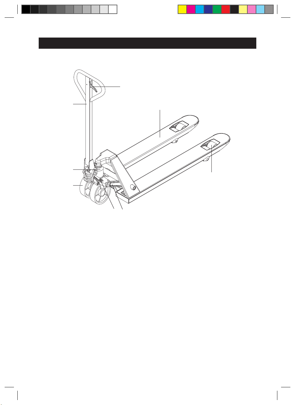
5. Parts description
4
5
6
3
2
1
78
1. Steering wheels
2. Pump unit
3. Tiller arm
4. Control lever
5. Forks
6. Load wheels
7. Lifting mechanism
8. Swing rod
(IM)237‐000413_RHP25_GB-IM_V4_150626.indd 8 7/3/15 17:09
-9-
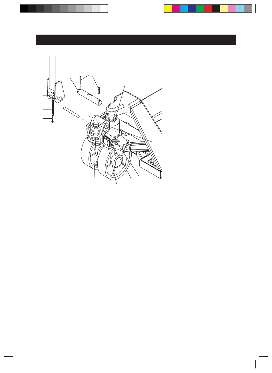
5. Parts description
3
i
j
h
a
bc
2
d
8e
f
g
a) Safety pin
b) Axle
c) Roll pin (x2)
d) Hinge
e) Adjusting screw
f) Hydraulic valve unit
g) Small piston rod
h) Roller
i) Adjusting bolt
j) Chain
(IM)237‐000413_RHP25_GB-IM_V4_150626.indd 9 7/3/15 17:09

-10-
6. Scope of delivery
1 pre-assembled chassis with pump unit
1 pre-assembled tiller arm
1 axle
2 roll pins
Please check the completeness of the delivery and ensure that all parts are free
from any transport-related damage or any damage in general. Please contact the
seller from whom you purchased the product should there be any parts missing
or damaged.
7. Before use
7.1 Unpacking
1. Unpack all parts and lay them on a flat, stable surface.
2. Remove all packing materials and shipping devices if applicable.
3. Make sure the delivery contents are complete and free of any damage. If you
find that parts are missing or show damage do not use the product but contact
your dealer. Using an incomplete or damaged product represents a hazard to
people and property.
4. Ensure that you have all the accessories and tools needed for assembly and
operation. This also includes suitable personal protective equipment.
WARNING!
The product and the packaging are not children’s toys! Children
must not play with plastic bags, sheets and small parts! There
is a danger of choking and suffocation!
7.2 Assembly
1. Insert the tiller arm (3) with the roller (h) facing the small piston rod (g) into
the hinge (d). Use a hammer to insert the axle (b) through the hinge (d) and
the tiller arm (3). Make sure the holes for the roll pins (c) are aligned with the
respective slots on the hinge (d).
2. Set the control lever (4) to the “lower” position. Pass the chain (j) and the
adjusting bolt (i) through the centre hole of the axle (b).
3. Use a hammer to insert the two roll pins (c) into the two outer holes of the axle
(b) aligned to the slots in the hinge (d).
4. Press the tiller arm (3) all the way down and hold it in position with one hand,
while removing the safety pin (a) from the hinge (d). Move the tiller arm (3)
back to the upright position.
(IM)237‐000413_RHP25_GB-IM_V4_150626.indd 10 7/3/15 17:09

-11-
7. Before use
5. Set the control lever (4) to the “lift” position. Raise the swing rod (8) and insert
the adjusting bolt (i) into the slot, with one nut each underneath and above the
swing rod (8).
6. Move the nuts on the adjusting bolt (i) close to the swing rod (8) so that it
cannot fall out of the slot. Do not tighten against each other!
7. Adjust the swing rod (8) (→ 7.3 Swing rod adjustment).
7.3 Swing rod adjustment
The control lever (4) on the tiller (3) and the swing rod (8) are linked to each other
and move respectively in the following three positions:
Control lever Swing rod Action Position
Lower
(pull and hold)
Neutral
(set before moving)
Lift
(set before pumping)
Adjust the swing rod according to following steps if necessary:
1. Set the control lever (4) to the “lift” position.
2. Turn the adjusting screw (e) on the swing rod (8) clockwise until it has contact
with the hydraulic valve unit (f) on the pump unit (2). Do not apply pressure!
3. Check if all three positions of the control lever (4) and the swing rod (8) are
working properly.
4. If the forks (5) elevate while pumping in the “neutral” position, turn the adjusting
screw (e) on the swing rod (8) clockwise until pumping action does not raise
the forks (5) and the “neutral” position works properly.
5. If the forks (5) descend while pumping in the “neutral” position, turn the
adjusting screw (e) on the swing rod (8) counter-clockwise until the forks (5)
do not lower.
(IM)237‐000413_RHP25_GB-IM_V4_150626.indd 11 7/3/15 17:09

-12-
7. Before use
6. If the forks (5) do not descend when the control lever (4) is in the “lower”
position, turn the adjusting screw (e) on the swing rod (8) clockwise until
pulling the control lever (4) lowers the forks (5). Check the “neutral” position
afterwards.
7. lf the forks (5) do not elevate while pumping in the “lift” position, turn the
adjusting screw (e) on the swing rod (8) counter-clockwise until the forks (5)
elevate while pumping in the “lift” position. Check the “lower” and “lift” position
afterwards.
8. Check again if all three positions of the control lever (4) and the swing rod (8)
are working properly and adjust again if not.
9. Tighten the nut on the adjusting screw (e) in swing rod (8).
8. Operation
NOTE: Always perform the “daily inspection” (→ 10.3 Daily
inspection) before putting the product into operation.
8.1 Parking
1. Lower the forks to the lowest position and park the product on a smooth and
even level ground where it will not disturb any other operations.
8.2 Lifting
1. Ensure that the load does not exceed the loading capacity.
2. Roll the product with its forks slowly under the goods until the back end of the
fork resists against the load.
3. The load must be evenly distributed across both forks.
4. Shift the control lever down to the “lift” position.
5. Lift the load by up and down movements of the tiller arm.
8.3 Moving
1. Always lower the forks as far as possible, while maintaining sufficient height
to manoeuvre.
2. Move the product by pushing or pulling the tiller arm.
3. The tiller arm is connected to the steering wheels. The wheels are steered
automatically by moving or steering the tiller arm.
(IM)237‐000413_RHP25_GB-IM_V4_150626.indd 12 7/3/15 17:09

-13-
8. Operation
8.4 Lowering
1. Lower the load by carefully shifting the control lever up to the “lower” position.
Ensure there are no obstacles below the load.
2. By releasing the control lever, the lowering movement will stop.
3. Be sure there is adequate clearance behind to remove the product from the
lowered goods.
9. Troubleshooting
Suspected malfunctions are often due to causes that the users can fix themselves.
Therefore check the product using this section. In most cases the problem can be
solved quickly.
WARNING!
Only perform the steps described within these instructions!
All further inspection, maintenance and repair work must
be performed by an authorised service centre or a similarly
qualified specialist if you cannot solve the problem yourself!
(IM)237‐000413_RHP25_GB-IM_V4_150626.indd 13 7/3/15 17:09

-14-
9. Troubleshooting
Problem Possible cause Solution
1. Forks do not
elevate, do not
elevate fully or
elevate slowly
1.1 Low hydraulic fluid
leveI or impurities in
oil
1.2 Swing rod is out of
adjustment
1.3 Load is too heavy.
Overload release
valve is being
activated
1.4 Temperature is
too low and the
hydraulic oil has
become too thick
1.5 Air in the hydraulic
oil
1. Add approved hydraulic
fluid or change the oil
(→ 10.7 Adding
hydraulic oil to the
pump reservoir)
2. Follow the procedure
for adjusting the swing
rod (→ 7.3 Swing rod
adjustment)
3. Reduce load
4. Move product to a
warmer location
5. Bleed the pump unit
(→ 10.6 Bleeding the
hydraulic system)
2. Forks do not
descend or do not
descend fully
2.1 Obstacle located
under the forks or in
lifting mechanism
2.2 Swing rod is out of
adjustment
2.3 Forks were left in an
elevated position for
an extended time
causing the exposed
big piston rod to rust
2.4 The big piston rod or
pump is deformed
due to over-loading
or uneven loading
1. Use caution removing
the obstacle
2. Follow the procedure
for adjusting the swing
rod (→ 7.3 Swing rod
adjustment)
3. Keep fork in the lowest
position when not
in use and keep the
big piston rod well
lubricated
4. Have the big piston rod
or pump unit replaced
(IM)237‐000413_RHP25_GB-IM_V4_150626.indd 14 7/3/15 17:09

-15-
9. Troubleshooting
Problem Possible cause Solution
3. Forks descend
without putting
the control lever
in the „lower“
position
3.1 Oil impurities are
preventing the
release valve from
fully closing
3.2 Some hydraulic
components or seals
are cracked or worn
3.3 Control lever is out
of adjustment
1. Drain and replace
hydraulic fluid with
approved fluid
2. Inspect and have
components replaced
as needed
3. Follow the procedure
for adjusting the swing
rod (→ 7.3 Swing rod
adjustment)
4. Oil leakage 4.1 Worn or damaged
seals
4.2 Other cracked or
worn parts
1. Have the seals replaced
2. Have the damaged
parts replaced
10. Cleaning, maintenance and repair
10.1 Cleaning
1. Clean the product after each use with a slightly damp cloth and a little soap.
Use brushes for hard to reach places.
2. Remove stubborn dirt with high pressure air (max. 3 bar).
3. Clean off dirt and debris every six month.
NOTE: Do not use chemical, alkaline, abrasive or other aggressive
detergents or disinfectants to clean this product as they might be
harmful to its surfaces.
10.2 Maintenance
1. Only qualified and trained personnel are allowed to do service on this product.
2. Before servicing the product, remove the load and lower the forks to the lowest
position. Completely immobilise the product before working on components
that might pinch fingers or hands if movement was allowed.
3. Spare parts are available from your seller or contact the manufacturer.
4. Consider that oil leakage of hydraulic fluid can cause failures and accidents.
5. It is allowed to adjust the pressure valve only from trained service technicians.
(IM)237‐000413_RHP25_GB-IM_V4_150626.indd 15 7/3/15 17:09

-16-
10. Cleaning, maintenance and repair
6. Waste material like oil, or others must be probably disposed of and recycled
according to the national regulation; if necessary, bring it to a recycling
company.
7. All bushings and bearings have been lubricated at factory. To increase their life
expectancy, regular maintenance is recommended.
8. Harsh environments may require more frequent maintenance.
10.3 Daily inspection
Visually check for structural deformation or cracks of arms, forks, or any other
component and unusual noise or binding of the lifting mechanism. Do not use the
product if any malfunction or fault is detected.
1. Check if there is any oil leakage.
2. Check the vertical movement of the lifting mechanism.
3. Check the smooth movement of the wheels.
4. Check if there are any particles or damages on the wheels.
5. Check if all the bolts and nuts are tightened firmly.
6. Verify that all labels are in place, undamaged and readable.
7. Check if all parts are functional as described within these instructions.
10.4 Monthly inspection
1. Check hydraulic oil level (more frequently for high use applications).
2. All bearings and shafts are provided with long-life grease at factory. Long-life
grease should be applied to the lubrication points at monthly intervals or after
each time the product is cleaned.
3. Change oil (more frequently if colour has substantially darkened or feels gritty)
(→ 10.7 Adding hydraulic oil to the pump reservoir).
NOTE: lf hydraulic oil is milky white in colour and water is in the
hydraulic system, change the hydraulic oil immediately.
10.5 Repair
This product does not contain any parts that can be repaired by the consumer.
Contact a qualified specialist to have it checked and repaired.
WARNING!
Always make sure all guards, if available, have been reinstalled
safely and correctly after each cleaning or maintenance
operation! Never use the product without its guards!
(IM)237‐000413_RHP25_GB-IM_V4_150626.indd 16 7/3/15 17:09

-17-
10. Cleaning, maintenance and repair
10.6 Bleeding the hydraulic system
Air may find its way into the pump during transportation, tilting or usage on uneven
ground. It can result in not elevating forks while pumping in the “lift” position. The
air can be removed in the following way:
1. Move the control handle to the “lower” position, and then move the tiller down
several times. Thereafter normal operation can be resumed.
10.7 Adding hydraulic oil to the pump reservoir
1. Make sure forks are in lowered position.
2. Lay the product on either side. Position the drain plug of hydraulic cylinder up.
3. Remove the screw plug.
4. Add hydraulic oil until level of oil is at bottom of the hole.
5. Change oil (more frequently if colour has substantially darkened or feels gritty).
The required hydraulic fluid type is ISO VG32, its viscosity should be 30 cSt at
400°C, total volume is about 0.3 I.
6. Replace drain plug, upright the product.
11. Storage and transportation
11.1 Storage
1. Clean the product as described above.
2. Remove the load and lower the product to its lowest position.
3. Store the product in a dry, frost-free place. Protect it from any kind of moisture.
4. Always store the product in a place that is inaccessible to children. The ideal
storage temperature is between 10°C and 30°C.
5. We recommend using the original package for storage or covering the product
with a suitable cloth to protect it against dust.
NOTE: Before using it again, use this instruction manual to check
the product for possible wear and damage.
11.2 Transportation
1. Remove the load and lower the product to its lowest position.
2. Lash it safe with dedicated lashing straps.
(IM)237‐000413_RHP25_GB-IM_V4_150626.indd 17 7/3/15 17:09
-18-
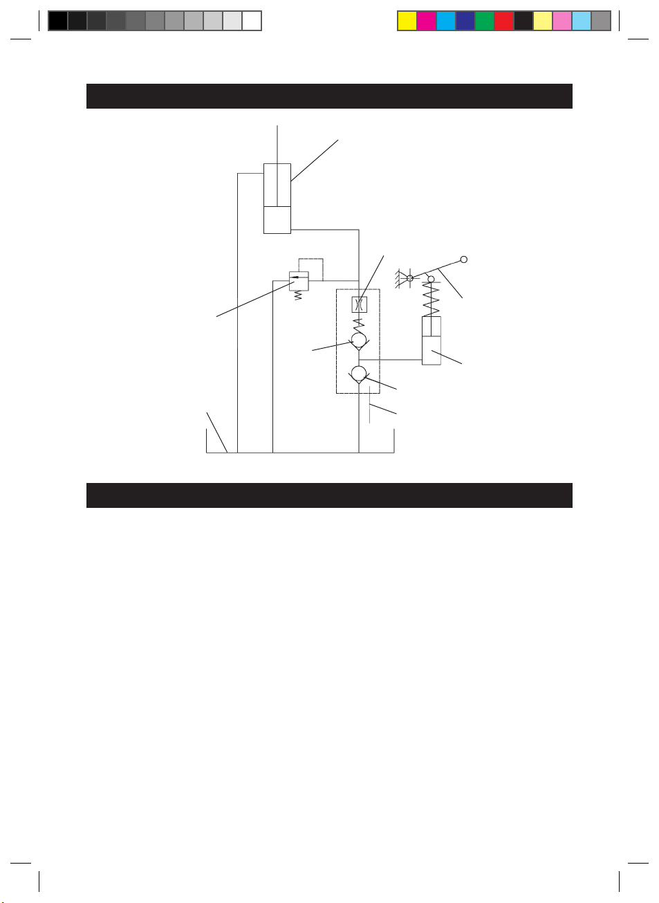
12. Hydraulic diagram
Cylinder
Valve
Valve
Valve
Lever
Oil tank
Tiller
Pump
Safety
valve
13. Disposal
Used products are recyclable materials and therefore do not belong in ordinary
household waste! We would therefore like to ask you to support us in the
conservation of resources and the protection of the environment, and hand this
product to return sites – where available.
(IM)237‐000413_RHP25_GB-IM_V4_150626.indd 18 7/3/15 17:09

-19-
14. Warranty
A statutory warranty applies for this product.
Damages caused by wrong treatment or operation, by false placement or storage,
improper connection or installation, as well as force or other external influences
are not covered by this warranty. We recommend careful reading of the operating
instructions as it contains important information.
Note:
1. In case this product does not function correctly, please firstly check if there are
other reasons, e.g. for electrical appliances interruption of the power supply, or
generally incorrect handling are the cause.
2. Please note that, where possible, the following documents or rather information
should be provided together with your faulty product:
– Purchase receipt
– Model description/Type/Brand
– Describe the fault and problem as detailed as possible
In the case of a claim for guarantee or defects, please contact the seller.
GWL 8/14 EN
RHP25 ENGLISH 150626
(IM)237‐000413_RHP25_GB-IM_V4_150626.indd 19 7/3/15 17:09
Table of contents
Popular Truck manuals by other brands


CUSTOM TRUCK
CUSTOM TRUCK LOAD KING 10 FT. DUMP BODY Operator's manual

Baxtran
Baxtran ARN manual

Still
Still ECH 12C Original instructions

Big Joe
Big Joe PDSR 30 Installation, operation, maintenance & repair parts

Still
Still EXH-SF 20 Original instructions

EP Equipment
EP Equipment CQD15S-E Operation manual


