haacon AX User manual

–1–
haacon hebetechnik gmbh
Geschäftsbereich Nutzfahrzeugtechnik
D-63920 Großheubach
Tel. + 49 (0) 93 71/66804-21
Fax + 49 (0) 93 71/66804-66
www.haacon.com
DE
GB
FR
ES
IT
NL
haacon AX Absattelstütze
Betriebsanleitung
(Originaltext)
haacon AX Landing gear
Manual
(Translation)
haacon AX Béquilles de nivelage
Manuel d‘utilisation et d‘entretien
(Traduction)
haacon AX Apoyo de desacoplamiento
Instrucciones de uso
(Traducción)
haacon AX
Stabilizzatore per semirimorchi
Istruzionie per l‘uso
(Traduzione)
haacon AX Opleggersteun
Gebruiksaanwijzing
(Vertaling)
haacon AX Noga podporowa
Instrukcja obsługi
(Tłumaczenie)
Competence in lifting technology
PL

–2–

–3–
1. BENUTZERGRUPPEN
Aufgaben Qualifikation
Bediener Bedienung,
Sichtprüfung
Einweisung anhand der
Bedienungsanleitung
Fachper-
sonal
Anbau, Abbau,
Reparatur, Wartung
Mechaniker
Prüfungen Befähigte Person
2. SICHERHEITSHINWEISE
Bestimmungsgemäßer Einsatz
Die Absattelstützen sind geeignet für den Anbau an Fahrzeuge mit
Luftfederung und dienen zum Abstellen von Trailern.
– Gerät nach den Angaben dieser Betriebsanleitung
betreiben.
– Nur in technisch einwandfreiem Zustand benutzen.
– Nur durch eingewiesenes Personal bedienen.
– Gerät nur auf ebenem Untergrund mit ausreichender
Tragfähigkeit benutzen.
Sicherheitsbewusstes Arbeiten
– Vor dem ersten Arbeiten Betriebsanleitung lesen.
– Immer sicherheits- und gefahrenbewusst arbeiten.
– Schäden und Mängel sofort dem Verantwortlichen melden.
– Gerät erst reparieren, dann weiterarbeiten!
Nicht erlaubt sind:
– Überlast (--> techn. Daten, Typen-/ Traglastschild)
– Aufenthalt von Personen unter der abgestützen Last.
Organisatorische Maßnahmen
– Abstellbereich von Personen und Hindernissen freihalten.
– Sicherstellen, dass diese Betriebsanleitung immer verfügbar ist.
– Sicherstellen, dass nur eingewiesenes Personal mit dem Gerät arbeitet.
– In regelmäßigen Abständen prüfen, ob sicherheits- und gefahrenbe-
wusst gearbeitet wird.
Weitere Vorschriften, die zu beachten sind
– Betriebssicherheitsverordnung (BetrSichV).
– Länderspezifische Vorschriften.
– Unfallverhütungsvorschrift.
3. TECHNISCHE DATEN
Bestellnr. Stütze
A795-1 A995-1 A520-1
Bestellnr. Paar A795 A995 A520
zul. Last / Stütze t 10 10 10
Zul. Last / Paar t 20 20 20
Fallhub mm 10 x 50 = 500 9 x 50 = 450 7 x 50 = 350
Gewicht / Stütze kg 19,5 21 12
Gewicht / Paar kg 39 42 24
Konstruktionsänderungen vorbehalten.
4. ALLGEMEINES
Die Absattelstützen sind für Stahl- und Aluminiumchassis geeignet und
können mit herkömmlichen Spindelstützen ausgetauscht werden.
Das Fallrohr wird mit einem federbelasteten unverlierbaren Absteckbol-
zen in 50 mm Rasterabstand gesichert.
Der Einsatz erfolgt paarweise oder einzeln.
5. AUFBAU / FUNKTION
Die Absattelstützen sind mit Pendelfuß ausgestattet.
Mit dem Fallrohr können Höhen schnell überbrückt werden.
6. MONTAGE
Montage nur durch Fachpersonal!
Die Absattelstützen mit 10 Schrauben M16 8.8 mit Unterlegscheiben
verschrauben. Anzugsmoment 190 Nm.
7. BEDIENUNG
Vor Inbetriebnahme Betriebsanleitung lesen.
zUnfallverhütungsvorschriften der Berufsgenossenschaft für Fahr-
zeughaltung und das Maschinenschutzgesetz beachten.
zBedienung nur durch eingewiesenes Personal.
zAbstellbereich von Personen und Hindernissen freihalten.
DE
20 t max !

–4–
DE
4. Schritt 3 an der zweiten Absattelstütze wiederholen.
Der Abstand zwischen dem Fuß und dem Boden muss für
beide Stützen gleich sein. Evtl. mit Unterlagen ausgleichen.
5. Zugmaschine mittels Luftfederung langsam ablassen, bis der Trailer
auf beiden Stützen steht.
Eine zu schnelle Absenkung könnte die Stützen beschädigen.
6. Luftleitungen und andere Verbindungen zwischen Zugma-
schine und Trailer trennen. Sattelkupplung öffnen. Zugmaschine
langsam wegfahren.
Ankuppeln
1. Zugmaschine vor den Trailer setzen.
Trailerbremse schliessen und Räder blockieren.
2. Zugmaschine auf Kupplungshöhe korrigieren.
3. Zugmaschine vorsichtig zurücksetzen und ankuppeln.
Trailer nicht zurückschieben wenn er auf den Stützen
steht. Stützen könnten beschädigt werden.
4. Der Kupplungsvorgang ist abgeschlossen, wenn die Sattelverriege-
lung eingerastet ist. Prüfen!
5. Zugmaschine und Trailer anheben. Stütze muss lastfrei sein.
6. Nach Entriegeln (2) Fallrohr (3) an Haltegriff (1) anheben und in Fahr-
stellung verriegeln.
Diesen Schritt an der zweiten Absattelstütze wiederholen.
7. Luftleitungen und andere Anschlüsse verbinden, Bremse lösen und
Unterlegkeile entfernen.
8. Vor Abfahrt korrekten Kupplungsvorgang prüfen!
1
2
3
4
5
Abkuppeln
1.
Zugmaschine und Trailer auf ebenem Untergrund positionieren.
Räder der Zugmaschine blockieren.
2. Am Trailer Feststellbremse betätigen und Räder blockieren.
Abgekoppelte Trailer verlieren nach einiger Zeit Luft aus der
Federung.
Dadurch bewegt sich der Trailer und könnte die Stützen
beschädigen. Abhilfe: Entlüften der Federung vor dem
Abkuppeln.
3. Fallrohr (3) durch Öffnen der Verriegelung (federbelasteter unverlier-
barer Steckbolzen) ausfahren.
ACHTUNG!
Beim Bedienen des Fallrohrs (3)
Haltegriff (1) benutzen. Fallrohr (3) lang-
sam in die jeweilige Endposition bewegen.
Fallrohr (3) nicht durch freien Fall in die je-
weilige Endposition bringen! Eigengewicht
des Fallrohrs beachten!
Ist die zu überbrückende Höhe länger als
das Fallrohr, kann dies aus dem Schaft
herausfallen. Das Fallrohr darf max. nur
bis zur letzten Bohrung herausgezogen
werden (max. Fallhub).
Die Verriegelung (2) nur öffnen, wenn die
Stütze unbelastet ist. Vor dem Belasten
der Stütze muss diese geschlossen sein.
2
1
1
1
2
3
2

–5–
8. WARTUNG
zWartung und Reparatur nur durch Fachpersonal!
zFür die Reparatur nur Original - Ersatzteile verwenden.
zAn sicherheitsrelevanten Teilen keine Änderungen und Umbauten
vornehmen.
zZusätzliche Anbauten dürfen die Sicherheit nicht beeinträchtigen.
zEs gelten die einschlägigen Vorschriften.
zNach Reparaturen Funktionsprüfung durchführen.
Reinigung
Reinigung der Absattelstütze mit der Fahrzeugpflege.
Wartungsanleitung
Wartungsarbeit Wartungsintervall
Sichtprüfung der Absattelstützen
auf Risse und Verformungen
Bei jedem Gebrauch der Absat-
telstützen, ggfs. beschädigte
Absattelstützen ersetzen
Mindestens im Rahmen der Fahrzeuginspektion sind die Absattelstützen
von einem Sachkundigen zu überprüfen; Insbesondere auf Schwergän-
gigkeit. Gegebenenfalls sind Verschleißteile auszutauschen.
10. ENTSORGUNG
Gerät und dessen Inhaltstoffe umweltgerecht entsorgen.
1. USER GROUPS
Duties Qualifications
Operator Operation,
visual inspection
Instruction by means of the operating
instructions
Specialist
personnel
Assembly, disassembly,
repair, maintenance
Mechanic
Tests Authorised person
2. SAFETY INSTRUCTIONS
Appropriate use
The trailer landing legs are suitable for attachment to vehicles with
pneumatic suspension and facilitate parking trailers.
– Only use when in perfect working order.
– Only allow to be operated by personnel instructed on how to do so.
– Only use the equipment on a substrate with sufficient
load-bearing capacity.
Safe working practices
– First read the operating instructions.
– Always be conscious of safety and hazards when working.
– Immediately report any damage or defects to the person in
charge.
– Repair equipment first before continuing work!
Do not:
– Overload (--> technical data, type plate, payload plate)
– Persons dwelling under the suspended load.
Organisational measures
– Keep parking area free of persons and hindrances.
– Ensure that these operating instructions are always at hand.
– Ensure that only trained personnel work with the equipment .
– Check at regular intervals whether it is being used in a safety and
hazard conscious manner.
Further regulations to be observed are
– German Industrial Health and Safety Ordinance.
– Country-specific regulations.
– German Accident prevention regulations.
DE
GB
20 t max !

–6–
GB
1
2
3
4
5
Decoupling
1.
Position the tractor and trailer on level ground.
Block the wheels of the tractor.
2. On the trailer, actuate the parking brake and block the wheels.
After a while, decoupled trailers lose air from their
suspension.
This causes the trailer to move and can damage
the supports. Remedy: Vent the suspension prior to
decoupling.
3. Extend the drop tube (3) by opening the locking mechanism (sprung
captive locking pin).
ATTENTION!
When operating the drop tube (3) use
the handle (1). Slowly move the drop tube
(3) to the respective limit position.
Do not bring the drop tube (3) to the
respective limit position through free-fall!
Observe the net weight of the drop tube!
If the height to be bridged is greater than
the length of the drop tube, this may fall
out of the shaft. The drop tube must not be
drawn out further than the last hole (max.
drop stroke).
Only open the locking mechanism (2)
when the support is not loaded. Before
the support is loaded this must be closed.
2
1
1
1
2
3
2
3. TECHNICAL DATA
O/No.
leg
A795-1 A995-1 A520-1
O/No.
pair
A795 A995 A520
Max. load / leg t 10 10 10
Max. load / pair t 20 20 20
Drop leg mm 10 x 50 = 500 9 x 50 = 450 7 x 50 = 350
Weight / leg kg 19,5 21 12
Weight / pair kg 39 42 24
Modifications of the design and execution reserved.
4. GENERAL
The trailer landing legs are suitable for steel and aluminium chassis and
are interchangeable with conventional spindle supports.
The drop tube is secured with a sprung captive plug-in pin and holes with
50 mm spacing.
Use takes place individually or in pairs.
5. CONSTRUCTION / FUNCTION
The trailer landing legs are equipped with rocking foot.
Using the drop tube it is possible to bridge heights quickly.
6. MONTAGE
Assembly by specialist personnel exclusively!
Bolt on the trailer landing legs with 10 screws of type M16 8.8 with
washers. Tightening torque 190 Nm.
7. OPERATION
Read the operating instructions prior to commissioning.
zObserve accident prevention regulations of the trade association for
vehicle ownership and the Safety of Machinery Act.
zOperation by trained personnel only.
zKeep parking area free of persons and hindrances.

–7–
4. Repeat step 3 with the second trailer landing leg.
The space between the foot and the ground must be
the same with both supports. If nec. balance out with shims.
5. Slowly lower the tractor with the pneumatic suspension, until
the trailer stands on both supports.
Lowering too quickly could damage the supports.
6. Disconnect air lines and other connections between
the tractor and trailer. Open the fifth-wheel coupling. Slowly drive
the tractor away.
Coupling
1. Position the tractor in front of the trailer.
Apply the trailer brake and block the wheels.
2. Adjust the tractor to the coupling height.
3. Carefully reverse the tractor and couple.
Do not push the trailer back whilst it is on the supports.
The supports may be damaged.
4. The coupling process is complete once the fifth-wheel locking
mechanism has latched. Check!
5. Raise the tractor and trailer. Support must be load-free.
6. After unlocking (2) raise the drop tube (3) at the handle (1) and lock in
driving position.
Repeat this step with the second trailer landing leg.
7. Connect air lines and other connections, release brake and remove
shims.
8. Check for correct coupling process prior to driving away!
8. MAINTENANCE RECOMMENDATION
Only allow the device to be serviced and repaired by trained personnel.
Only use genuine spare parts for repair work.
Do not make any modifications or additions to parts with a safety function.
Additional mountings must not adversely affect safety.
The relevant regulations apply.
Test the function after repair.
Cleaning
Clean the support device as part of your normal vehicle care.
Servicing instructions
Servicing work Servicing interval
Conduct a visual inspection of the
landing gears for signs of cracks
an deformation
Each time you use the support
device. Replace damaged trailer
landing legs
The landing gears must be checked by an expert at least during the
normal vehicle inspection routine, particularly for stiffness. If necessary
wear parts are to be replaced.
10. WASTE DISPOSAL
The disposal of the product and its components has to be according to
environmental standards.
GB

–8–
FR
3. DONNÉES TECHNIQUES
N° Code
béquille A795-1 A995-1 A520-1
N° Code
paire A795 A995 A520
Charge autorisée /
béquille t10 10 10
Charge autorisée /
paire
t 20 20 20
Course de descente
mm 10 x 50 = 500 9 x 50 = 450 7 x 50 = 350
Poids / béquille kg 19,5 21 12
Poids / paire kg 39 42 24
Sous réserve de modifications.
4. GÉNÉRALITÉS
Les béquilles télescopiques conviennent aux châssis en acier et en alu-
minium et peuvent se substituer avec des béquilles conventionnels.
Le tuyau de chute se bloque au moyen d’un mécanisme de verrouillage
par broche imperdable avec un espacement de 50 mm.
Il peut être utilisé individuellement ou par paire.
5. EQUIPEMENT / FONCTION
Les béquilles télescopiques sont dotées d‘un patin pivotant.
Le tuyau de chute permet de dompter rapidement les hauteurs.
6. MONTAGE
Montage réservé à un personnel spécialisé !
Visser les béquilles télescopiques avec 10 vis M16 8.8 et des rondelles.
Couple de 190 Nm.
7. UTILISATION
Avant la mise en service, lire la notice d’utilisation.
zRespecter les prescriptions de prévention des accidents édictées par
les syndicats nationals et la loi sur la protection des machines.
zManipulation réservée à du personnel initié.
zPersonne ni rien ne doit se trouver dans la zone de stationnement.
1. GROUPES D’UTILISATEURS
Missions Qualification
Opérateur Commande,
examen visuel
Initiation à l'aide de la notice
d'utilisation
Personnel
spécialisé
Montage, démontage,
réparation, entretien
Mécanicien
Contrôles Personne qualifiée
2. CONSIGNES DE SECURITE
Utilisation conforme
Les béquilles télescopiques peuvent être montées sur des véhicules dotés
d‘une suspension pneumatique et servent à stationner
les remorques.
– Utiliser uniquement dans un parfait état.
– Commande uniquement par le personnel formé.
– L‘appareil ne doit être utilisé que sur une surface
présentant une capacité de charge suffisante.
Travaux effectués en toute sécurité
– Lire préalablement la notice d‘utilisation.
– Toujours travailler en ayant conscience de la sécurité et des dangers.
– Signaler immédiatement au responsable les dommages et défauts.
– Réparer d‘abord l‘appareil, puis poursuivre le travail!
A proscrire:
– Surcharge (--> données techn., plaque signalétique/
de capacité)
– Personnes séjournant sous la charge soulevée.
Mesures organisationnelles
– Personne ni rien ne doit se trouver dans la zone de stationnement
.
– S’assurer que la présente notice d’utilisation est toujours disponible.
– S’assurer que seul le personnel formé travaille avec l’appareil .
– Vérifier, à intervalles réguliers, si le travail est effectué en ayant conscience
de la sécurité et des dangers.
Autres directives à observer
– Ordonnance relative à la sécurité dans l’entreprise.
– Directives nationales.
– Ordonnance relative à la prévention des accidents.
20 t max !

–9–
1
2
3
4
5
Découpler
1.
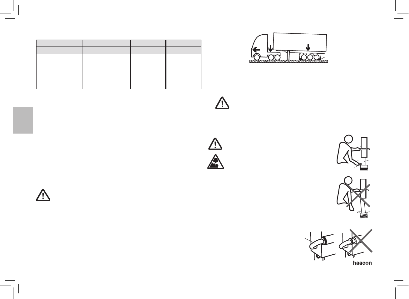
Positionner le tracteur et la remorque sur un sol plan.
Bloquer les roues du tracteur.
2. Actionner le frein de stationnement de la remorque et bloquer les roues.
Au bout d‘un certain temps, de l‘air s‘échappe par la
suspension des remorques découplées.
Sous l‘effet de ce phénomène, la remorque se déplace et
risque d‘endommager les béquilles. Solution : Purge de la
suspension avant découplage.
3. Déployer le tuyau de chute (3) en ouvrant le verrouillage (mécanisme
de verrouillage par broche imperdable).
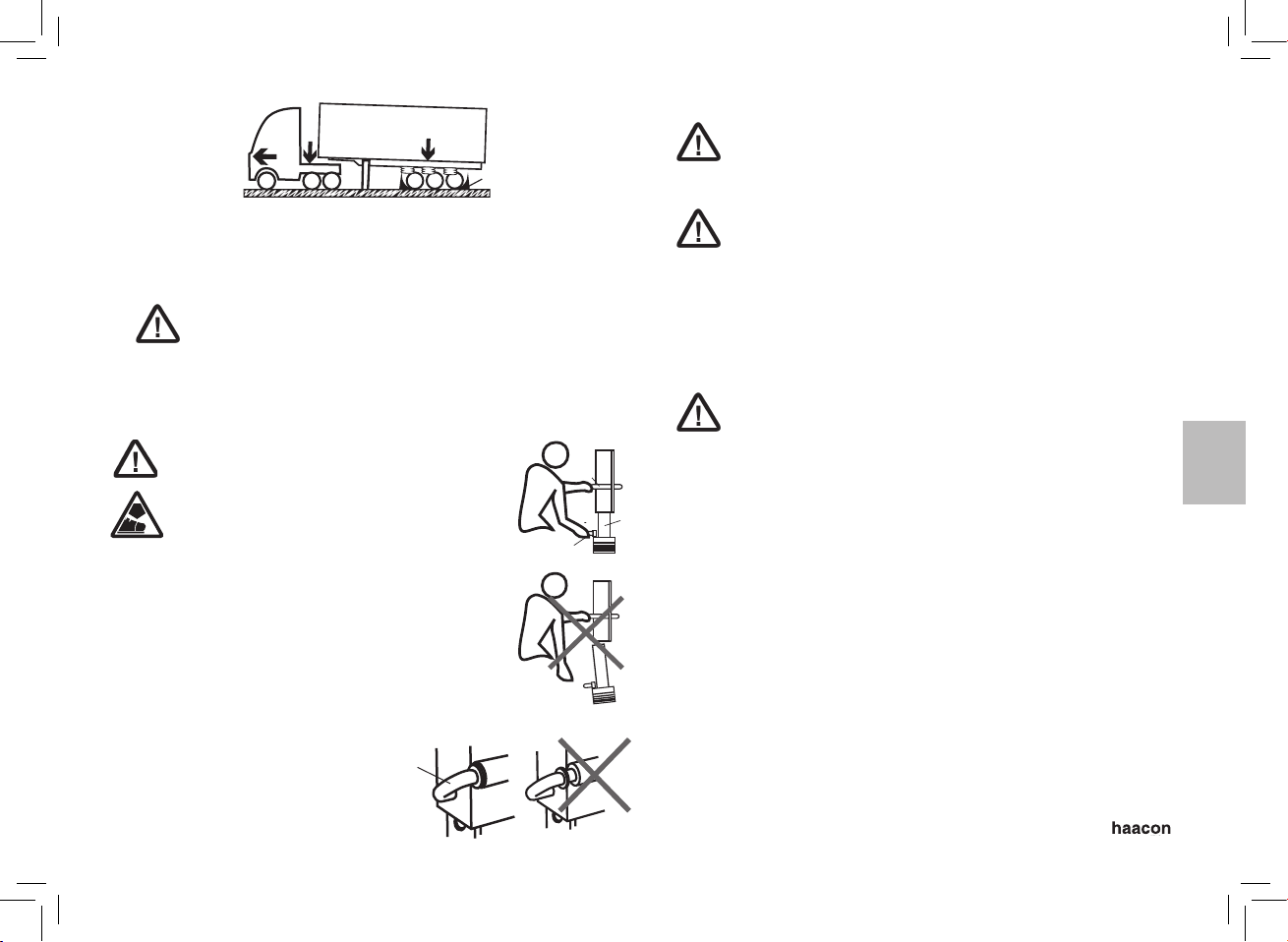
ATTENTION!
Lors de la commande du tuyau de chute
(3), utiliser la poignée (1). Déplacer
lentement le tuyau de chute (3) jusqu‘à
l‘amener en position finale.
Ne pas amener le tuyau de chute (3) en position
finale par le biais d‘une chute libre ! Prendre en
compte le poids propre du tuyau de chute !
Si la hauteur à franchir est plus longue
que le tuyau de chute, celui-ci risque
de tomber de l‘arbre. Le tuyau de chute
ne doit pas être sorti au-delà du dernier
alésage (course de descente max.).
N‘ouvrir le verrouillage (2) que si la
béquille n‘est pas sous charge. Avant
de charger la béquille, celle-ci
doit être fermée.
4. Répéter l‘étape 3 au niveau de la deuxième béquille.
L‘écart entre le pied et le sol doit être identique pour les deux
béquilles. Au besoin, compenser par des supports.
5. Vidanger lentement le tracteur à l‘aide de la suspension pneumatique
jusqu‘à ce que la remorque repose sur les deux béquilles.
Une descente rapide risque d‘endommager les béquilles.
6. Débrancher les conduites pneumatiques et autres raccords
entre le tracteur et la remorque. Ouvrir la sellette d‘attelage. Déplacer
lentement le tracteur.
Coupler
1. Positionner le tracteur devant la remorque.
Fermer le frein de la remorque et bloquer les roues.
2. Corriger la hauteur de couplage du tracteur.
3. Remettre en place prudemment le tracteur et le coupler.
Ne pas faire reculer la remorque s‘il repose sur les
béquilles. Les béquilles risquent d‘être endommagées.
4. Le processus de couplage est terminé une fois le verrouillage
de sellette enclenché. Contrôler !
5. Soulever le tracteur et la remorque. La béquille doit être libérée
de toute charge.
6. Après déverrouillage (2), soulever le tuyau de chute (3) au niveau
de la poignée (1) et le verrouiller en position de conduite.
Répéter cette étape au niveau de la deuxième béquille.
7. Connecter les conduites pneumatiques et autres raccords, desserrer
le frein et retirer les cales.
8. Avant de partir, vérifier que le processus de couplage est correct !
FR
2
1
1
1
2
3
2

–10 –
ES
1. GRUPOS DE USUARIOS
Tareas Cualificación
Operario Manejo,
revisión visual
Instrucción mediante el
manual de instrucciones
Personal
técnico
Montaje, desmontaje, repara-
ciones, mantenimiento
Mecánico
Revisiones Persona capacitada
2. INDICACIONES DE SEGURIDAD
Uso conforme a lo previsto
Las patas de semirremolque son apropiadas para el adosamiento en vehículos
con suspensión neumática y se usan para la colocación de remolques.
– Utilizar solo en perfecto estado técnico.
– Únicamente podrán utilizarlo las personas adecuadamente instruidas.
– Utilizar el aparato únicamente en un suelo con sufici-
ente capacidad de carga.
Trabajar pensando en la seguridad
– En primer lugar, leer el manual de instrucciones.
– Trabajar siempre de forma segura y teniendo en cuenta los
riesgos.
– Avisar de inmediato al responsable si se detectan daños y
defectos.
– Una vez esté reparado se puede seguir trabajando.
No se permite:
– Sobrecarga (--> datos técnicos, placa de
características/cargas admisibles)
– Presencia de personas bajo la carga apuntalada.
Medidas de organización
– Mantener a las personas y los obstáculos fuera la zona de colocación.
– Asegurar la disponibilidad de este manual de instrucciones en cual-
quier momento.
– Asegurarse de que únicamente el personal cualificado trabaja con el aparato.
– Comprobar regularmente que la máquina se utiliza de formasegura y
teniendo en cuenta los riesgos.
Otras normativas que se deben tener en cuenta
– Reglamento de seguridad en el trabajo.
– Disposiciones específicas del país.
– Disposición sobre prevención de accidentes.
20 t max !
FR
8. RECOMMANDATION DE MAINTENANCE
Seul un personnel spécialisé est autorisé à exécuter les travaux de main-
tenance et les réparations!
Utiliser uniquement les pièces détachées d‘origine pour les réparations.
N‘effectuer aucune modification, ni transformation sur les composants
importants pour la sécurité.
Les autres produits rajoutés ne doivent pas nuire à la sécurité. Respecter
les prescriptions applicables.
Après la réparation vérifier la fonctionnement.
Nettoyage
Nettoyer les béquilles télescopiques pendant l‘entretien du véhicule.
Instructions de maintenance
Tâche de maintenance Période de maintenance
Contrôler visuellement si les bé-
quilles de nevilage sont fissurées
ou déformées.
A chaque utilisation des béquilles
de nevilage.
Remplacer les béquilles
télescopiques endommagées
Les béquilles de nevilage doit être contrôlé par un expert, au moins dans
le cadre de l‘inspection du véhicule, en particulier quant au grippage.
Remplacer les pièces usées si nécessaire.
10. DÉMONTAGE ET ÉLIMINATION DES DÉCHETS
L‘élimination des déches de l‘appareil ainsi que de ses composants doit
être conforme aux standards écologiques.

–11 –
3. DATOS TÉCNICOS
O/No.
Soporte A795-1 A995-1 A520-1
O/No. Par A795 A995 A520
Carga / soporte
permitido t10 10 10
Carga / par
permitido t 20 20 20
Carrera de caida mm 10 x 50 = 500 9 x 50 = 450 7 x 50 = 350
Peso / Soporte kg 19,5 21 12
Peso / Par kg 39 42 24
Reservados los derechos de modificación en la construcción y diseño.
4. GENERALIDADES
Las patas de semirremolque son apropiadas chasises de acero
y aluminio y pueden intercambiarse por soportes comunes de husillo.
El tubo bajante se asegura mediante un perno de enganche imperdible
sometido a carga de resorte con una distancia de retícula de 50 mm.
Se utiliza en pares o de forma individual.
5. ESTRUCTURA/FUNCIONAMIENTO
Las patas de semirremolque están provistas de bases reversibles.
Con el tubo bajante pueden puentearse rápidamente las alturas.
6. MONTAJE
Únicamente el personal técnico debe realizar el montaje.
Atornillar las patas de semirremolque con 10 tornillos M16 8.8 con
arandelas. Par de arranque 190 Nm.
7. MANEJO
Leer estas instrucciones de uso antes de usar por primera vez..
zTener en cuenta los reglamentos de las asociaciones profesionales
relativos a la prevención de accidentes de para el mantenimiento
de vehículos y la ley sobre instrumentos técnicos de trabajo.
zEl manejo está a cargo solamente del personal instruido.
zMantener a las personas y los obstáculos fuera la zona
de colocación.
1
2
3
4
5
Desenganche
1.
Posicionar el tractor y el remolque sobre un fondo plano.
Bloquear las ruedas del tractor.
2. Accionar los frenos de bloqueo en el remolque y bloquear las ruedas.
Después de cierto tiempo, los remolques enganchados
pierden el aire de la suspensión.
Debido a esto, el remolque se desplaza y podría dañar las
patas. Solución: Evacua el aire de la suspensión antes del
enganche.
3. Subir el tubo bajante (3) a través del orificio de bloqueo (perno
de enganche imperdible sometido a carga de resorte).
ATTENTION!
Utilizar el pasamanos (1), durante el
manejo del tubo bajante (3). Desplazar
el tubo bajante (3) lentamente hacia la
posición terminal correspondiente.
No desplazar el tubo bajante (3) en caída libre
hacia la posición terminal correspondiente.
Tener en cuenta el peso propio del tubo bajante.
Si la altura por puentear es mayor que la
del tubo bajante, este puede salirse del
vástago. El tubo bajante debe retirarse
como máximo hasta el último orificio (máx.
del tubo bajante).
Abrir el bloqueo (2) solo si la pata se
encuentra sin carga. Antes
de cargar la pata, este última
debe estar cerrada.
ES
2
1
1
1
2
3
2

–12 –
8. MANTENIMIENTO RECOMENDADO
Mantenimiento y reparación sólo por personal especializado!
Emplear para la reparación sólo piezas de recambio originales.
En piezas importantes para la seguridad no efectuar ninguna modifica-
ción ni reconstrucción.
Los dispositivos adicionales no deben comprometer la seguridad.
Hay que cumplir las especificaciones pertinentes.
Realizadas las reparaciones necesarias, efectúe las pruebas de función
requeridas
Limpieza
Limpieza del pie de apoyo al limpiar el vehículo.
Instrucciones de mantenimiento
Trabajos de inspección y mante-
nimiento
Intervalo de mantenimiento
Inspeccionar visualmente las
patas de semirremolque en busca
de grietas y deformaciones
Antes de cada uso de las patas
de semirremolque. Reemplazar las
patas de semirremolque dañadas
Al menos, en el marco de las inspecciones de vehículos, un perito
debe revisar las patas de semirremolque, en particular, en lo relativo
a su dureza. En caso necesario, se deben reemplazar las piezas
desgastadas.
10. DESMONTAJE, ELIMINACIÓN
Eliminar el aparato y los materiales que contiene de forma respetuosa
con el medio ambiente.
ES
4. Repetir el paso 3 en la segunda pata de semirremolque.
La distancia entre la base y el suelo debe ser la misma para
ambas patas. Posiblemente sea necesario nivelar con zapatas.
5. Purgar el tractor lentamente por medio de la suspensión neumática
hasta que ambas patas quedan firmes.
Un descenso demasiado rápido podría dañar las patas.
6. Separar las tuberías de aire y el resto de las conexiones entre
el tractor y el remolque. Abrir la quinta rueda. El tractor se conduce
lentamente.
Enganchar
1. Colocar el tractor delante del remolque.
Ajustar los frenos del remolque y bloquear las ruedas.
2. Corregir la altura del enganche en el tractor.
3. Retirar y enganchar cuidadosamente el tractor.
No empujar hacia atrás el remolque cuando esta sobre
las patas. Las patas podrían dañarse.
4. El procedimiento de enganche concluye cuando encaja el bloqueo
de la silleta. Comprobar.
5. Levantar el tractor y el remolque. La pata debe estar si carga.
6. Después de desbloquear (2), levantar el tubo bajante (3) en el
pasamanos (1) y bloquear en la posición de marcha.
Repetir este paso en la segunda pata de semirremolque.
7. Conectar las tuberías de aire y el resto de las conexiones, soltar los
frenos y retirar las calzas de soporte.
8. Comprobar el procedimiento de enganche correcto antes del
desplazamiento

–13 –
1. GRUPPI UTENTE
Mansione Qualifica
Operatore Uso, controllo visivo Formazione come da
istruzioni per l'uso
Personale
specializ-
zato
Montaggio, smontaggio,
riparazione, manutenzione
Meccanico
Collaudi Persona autorizzata
2. NORME DI SICUREZZA
Utilizzo conforme alla disposizioni
I supporti di sgancio sono idonei per l‘installazione su veicoli
con sospensioni pneumatiche e servono per lo
stazionamento di rimorchi.
– Utilizzare solo in condizioni tecniche perfette.
– Comando solo da personale appositamente istruito.
– Utilizzare l‘apparecchio solo su una superficie di fondo
con una capacità di carico sufficiente.
Lavoro in condizioni di sicurezza
– Leggere le istruzioni prima dell‘uso.
– Lavorare sempre tenendo ben presenti la sicurezza e i rischi.
– Comunicare immediatamente danni e anomalie alla persona responsabile.
– Provvedere alla riparazione dell‘apparecchio prima di riprendere il lavoro!
Non è consentito:
– Sovraccarico (--> dati tecnici, targhetta dati/carico
massimo).
– Sosta di persone sotto ai carichi sospesi.
Misure organizzative
– Mantenere libera da persone e ostacoli l‘area di stazionamento.
– Assicurarsi che le istruzioni per l’uso siano sempre disponibili.
– Assicurarsi che solo personale istruito lavori con l’apparecchio .
– A intervalli regolari controllare se si può lavorare tenendo ben presenti
la sicurezza e i rischi.
Ulteriori disposizioni a cui attenersi sono:
– Normativa inerente la sicurezza sul lavoro.
– Normative nazionali specifiche.
– Normativa antinfortunistica.
3. DATI TECNICI
O/No.
Supporto A795-1 A995-1 A520-1
O/No.
Coppia A795 A995 A520
Carico / supporto
ammessi t10 10 10
Carico / coppia
ammessi t 20 20 20
Corsa di caduta
mm 10 x 50 = 500 9 x 50 = 450 7 x 50 = 350
Peso / Supporto kg 19,5 21 12
Peso / Coppia kg 39 42 24
Modifiche di costruzione e versione riservate.
4. GENERALITÀ
I supporti di sgancio sono idonei per chassis in acciaio e in alluminio
e possono essere sostituiti con supporti a mandrino convenzionali.
Il tubo a scorrimento è fissato mediante un perno di sgancio perenne
e caricato a molla, con una distanza di retinatura pari a 50 mm.
Si possono utilizzare in coppia o singolarmente.
5. STRUTTURA / FUNZIONE
I supporti di sgancio sono corredati di piedini regolabili.
Con il tubo a scorrimento si possono coprire rapidamente le altezze necessarie.
6. MONTAGGIO
Montaggio solo a cura di personale specializzato!
Avvitare i supporti di sgancio con 10 viti M16 8,8 con rondelle.
Coppia di serraggio 190 Nm.
7. UTILIZZO
Prima della messa in servizio leggere le istruzioni per l‘uso.
zOccorre rispettare le norme antinfortunistiche della BGF
(Berufsgenossenschaft für Fahrzeughaltungen - Associazione professionale
degli operatori di veicoli) e la legge sulla protezione delle macchine.
zImpiego solo a cura di personale appositamente istruito.
zMantenere libera da persone e ostacoli l‘area di stazionamento.
IT
20 t max !

–14 –
IT
4. Ripetere il passo 3 per il secondo supporto di sgancio.
La distanza tra il piede e il terreno deve essere uguali per
entrambi i supporti. Event. compensare con .supporti.
5. Scaricare il rimorchio tramite le sospensioni pneumatiche,
lentamente finché il rimorchio si trova su entrambi i supporti.
Un abbassamento troppo rapido potrebbe danneggiare i
supporti.
6. Scollegare le tubazioni dell‘aria e altri collegamenti tra la motrice e il
rimorchio. Aprire la ralla. Spostare lentamente la motrice.
Aggancio
1. Posizionare la motrice davanti al rimorchio.
Chiudere il freno del rimorchio e bloccare le ruote.
2. Modificare la motrice in base all‘altezza del giunto.
3. Spostare indietro la motrice con cautela e agganciare.
Non spostare indietro il rimorchio quando si trova sui
supporti. Si potrebbero danneggiare i supporti.
4. La procedura di aggancio è completata quando le chiusure sono
scattate in posizione. Verificare!
5. Sollevare la motrice e il rimorchio. I supporti devono essere privi
di carico.
6. Dopo aver tolto la chiusura (2) sollevare il tubo a scorrimento (3) sulla
maniglia (1) e bloccare in posizione di marcia.
Ripetere questo passo per il secondo supporto di sgancio.
7. Collegare le tubazioni dell‘aria e gli altri collegamenti. Allentare il
freno e rimuovere i cunei.
8. Prima della partenza verificare che la procedura di aggancio sia stata
eseguita correttamente!
1
2
3
4
5
Sganciamento
1.
Posizionare la motrice e il rimorchio su un terreno piano.
Bloccare le ruote della motrice.
2. Azionare il freno di stazionamento del rimorchio e bloccare le ruote.
I rimorchi sganciati dopo un certo lasso di tempo perdono
aria dalle sospensioni.
Di conseguenza il rimorchio si sposta e potrebbe danneggiare
i supporti. Rimedio: scaricare aria dalle sospensioni prima
dello sganciamento.
3. Estrarre il tubo a scorrimento (3) aprendo la chiusura (perno
di sgancio perenne caricato a molla)
ATTENTION!
Per manovrare il tubo a scorrimento (3) utilizzare
la maniglia (1). Muovere lentamente il tubo a
scorrimento (3) nella rispettiva posizione finale.
Non portare il tubo a scorrimento (3) nella
rispettiva posizione finale in caduta libera!
Fare attenzione al peso specifico del tubo
a scorrimento!
Se l‘altezza da coprire è maggiore della
lunghezza del tubo a scorrimento, questo
potrebbe cadere dall‘asta. Il tubo a
scorrimento deve essere estratto al massimo
fino all‘ultimo foro (max corsa di caduta).
Aprire le chiusure (2) solo quando
i supporti sono scarichi. Prima di caricare
i supporti questi devono essere
chiusi. 2
1
1
1
2
3
2

–15 –
8. MANUTENZIONE CONSIGLIATA
La manutenzione e la riparazione vanno eseguite solo da personale
specializzato!
Per la riparazione vanno utilizzati soltanto pezzi di ricambio originali.
Sulle parti di rilievo per la sicurezza non vanno eseguite modifiche né
trasformazioni.
Eventuali elementi aggiunti non devono pregiudicare la sicurezza.
Valgono le norme specifiche in materia.
Al termine degli interventi di riparazione eseguire il controllo del funzio-
namento.
Pulizia
Pulizia del sollevatore con la cura del veicolo.
Istruzioni per la manutenzione
Lavori di ispezione e manutenzione
Intervalli di manutenzione
Controllo visivo della presenza
di crepe e deformazioni dei
supporti di sgancio
Per ogni utilizzo dei supporti
di sgancio. Sostituire i supporti
di sgancio danneggiati
Almeno nell‘ambito dell‘ispezione del veicolo i supporti di sgancio
devono essere verificati da un esperto; in particolare per quanto riguarda
la rigidità. Eventualmente dovranno essere sostituite le parti soggette a
usura.
10. SMALTIMENTO
Smaltire l’apparecchio e i relativi materiali nel rispetto dell’ambiente.
IT
NL
1. GEBRUIKERSGROEPEN
Taken Kwalificatie
Bediener Bediening, visuele
controle
Instructie aan de hand van de
bedieningshandleiding
Vakperso-
neel
Monteren, demonteren,
reparatie, onderhoud
Mechanisch monteur
Keuringen Bevoegde persoon
2. VEILIGHEIDSVOORSCHRIFTEN
Bedoeld gebruik
De opleggersteunen zijn geschikt voor montage bij voertuigen met
luchtvering en dienen voor het parkeren van trailers.
– Alleen in technisch probleemloze toestand gebruiken.
– Bediening alleen door geïnstrueerd personeel.
– Apparaat alleen gebruiken op een ondergrond met
voldoende draagvermogen.
Veiligheidsbewust werken
– Eerst gebruiksaanwijzing lezen.
– Altijd veiligheids- en gevarenbewust werken.
– Schade en gebreken direct aan de verantwoordelijke melden.
– Toestel eerst repareren, daarna verder werken!
Niet toegestaan zijn:
– Overbelasting (--> technische gegevens, type-/
draaglastplaatje)
– Personen onder de afgesteunde last.
Organisatorische maatregelen
– Parkeerlocatie vrijhouden van personen en hindernissen.
– Waarborgen dat deze gebruiksaanwijzing altijd beschikbaar is.
– Waarborgen dat alleen geschoold personeel met het apparaat werkt.
– Regelmatig controleren of veiligheids- en gevarenbewust wordt gewerkt.
Overige voorschriften die moeten worden opgevolgd
– Bedrijfsveiligheidsverordening.
– Landspecifieke voorschriften.
– Ongevalpreventievoorschrift.
20 t max !

–16 –
NL
1
2
3
4
5
Afkoppelen
1.
Trekker en trailer op een vlakke ondergrond plaatsen.
Wielen van de trekker blokkeren.
2. Op de trailer de handrem activeren en de wielen blokkeren.
Afgekoppelde trailers verliezen na enige tijd lucht uit
de vering.
Hierdoor beweegt de trailer en kan de steun worden
beschadigd. Oplossing: Vering ontluchten voor het
afkoppelen.
3. Valbuis (3) door het openen van de vergrendeling (veerbelaste
en tegen verlies beveiligde insteekpen) uitschuiven.
ATTENTION!
Bij het bedienen van de valbuis (3)
greep (1) gebruiken. Valbuis (3) langzaan
naar betreffende eindpositie bewegen.
Valbuis (3) niet door vrije val in de
betreffende eindpositie brengen! Houd
rekening met het eigengewicht van de
valbuis!
Is de te overbruggen hoogte groter dan
de valbuis, kan deze uit de schacht vallen.
De valbuis mag maximaal tot de laatste
boring worden uitgetrokken (max. valslag).
De vergrendeling (2) alleen openen als
de steun onbelast is. Voor het belasten
van de steun moet de vergrendeling
gesloten zijn.
3. TECHNISCHE GEGEVENS
O/No.
Steun
A795-1 A995-1 A520-1
O/No. Paar A795 A995 A520
Toegestane last /
Steun t10 10 10
Toegestane last /
paar t 20 20 20
Verstelling mm 10 x 50 = 500 9 x 50 = 450 7 x 50 = 350
Gewicht / Steun kg 19,5 21 12
Gewicht / Paar kg 39 42 24
Wijzigingen in de constructie en uitvoering voorbehouden.
4. ALGEMEEN
De opleggersteunen zijn geschikt voor chassis van staal en aluminium
en kunnen onderling worden gewisseld met de gebruikelijke
spindelsteunen.
De valbuis wordt met een veerbelaste en tegen verlies beveiligde
insteekpen in boringen om de 50 mm geborgd.
De toepassing gebeurt in paren of individueel.
5. OPBOUW/FUNKTIE
De opleggersteunen zijn uitgerust met pendelvoeten.
Met de valbuis kunnen hoogten snel worden overbrugd.
6. INSTALLATIE
Montage alleen door vakpersoneel!
De opleggersteunen met 10 bouten M16 8.8 met onderlegringen
vastschroeven. Aanhaalmoment 190 Nm.
7. BEDIENING
Lees voor het in gebruik nemen de gebruiksaanwijzing.
zOngevalpreventievoorschriften van de bedrijfsvereniging voor
voertuigbeheer en de machinerichtlijn opvolgen.
zBediening alleen door geïnstrueerd personeel.
zParkeerlocatie vrijhouden van personen en hindernissen. 2
1
1
1
2
3
2

–17 –
4. Stap 3 herhalen bij de tweede opleggersteun.
De afstand tussen de voet en de ondergrond moet voor beide
steunen hetzelfde zijn. Evt. met onderlegmateriaal compenseren.
5. Trekker via luchtvering langzaam laten zakken, tot de trailer op
beide steunen staat.
Door het te snel laten zakken kunnen de steunen worden
beschadigd.
6. Luchtleidingen en andere verbindingen van de trekker en trailer
scheiden. Opleggerkoppeling openen. Trekker langzaam wegrijden.
Koppelen
1. Trekker voor trailer plaatsen.
Trailerrem sluiten en de wielen blokkeren.
2. Trekker corrigeren naar koppelhoogte.
3. Trekker voorzichtig achteruit rijden en koppelen.
Trailer niet achteruit schuiven als hij op de steunen
staat. De steunen kunnen worden beschadigd.
4. De koppelprocedure is afgesloten, als de vergrendeling van
de opleggerkoppeling is vergrendeld. Controleren!
5. Trekker en trailer heffen. Steun moeten onbelast zijn.
6. Na het ontgrendelen (2) valbuis (3) bij greep (1) optillen
en vergrendelen in de rijstand.
Deze stap herhalen bij de tweede opleggersteun.
7. Luchtleidingen en andere verbindingen aansluiten, rem lossen
en wielblokken verwijderen.
8. Voor het wegrijden de koppelprocedure controleren!
8. ONDERHOUDSAANBEVELINGEN
Onderhoud en reparatie uitsluitend door vakbekwaam personeel!
Voor reparatie alleen originele onderdelen gebruiken.
Aan veiligheidsgerelateerde onderdelen mag niets worden gewijzigd of
aangepast.
Aangebouwde opties mogen de veiligheid niet beïnvloeden.
Geldende voorschriften blijven van kracht.
Na reparaties een werkingscontrole verrichten.
Reiniging
Reiniging van de steunen tijdens voertuigonderhoud.
Onderhouds voorschrift
Inspectie- en onderhoudswerk-
zaamheden
Onderhoudsvoorschrift
Visuele controle van
de opleggersteunen op scheuren
en vervormingen
Bij elk gebruik van
de opleggersteunen. Beschadigde
opleggersteunen vervangen
Minimaal moeten de opleggersteunen in het kader van
de voertuiginspectie door een deskundige worden gecontroleerd, vooral
op stroef bewegen. Eventueel moeten de slijtdelen worden vervangen.
10. AFVOER AAN HET EINDE VAN DE LEVENSDUUR
Apparaat en materialen volgens de milieuregels afvoeren.
NL

–18 –
PL
3. DANE TECHNICZNE
O/No.
podpora A795-1 A995-1 A520-1
O/No. para A795 A995 A520
Dop. obciążenie /
podpora t10 10 10
Dop. obciążenie /
para t 20 20 20
Wysokość
teleskopowa mm 10 x 50 = 500 9 x 50 = 450 7 x 50 = 350
Ciężar / podpora kg 19,5 21 12
Ciężar / para kg 39 42 24
Zastrzega się prawa do zmian konstrukcyjnych i wykonawczych.
4. INFORMACJE OGÓLNE
Nogi podporowe są przystosowane do stalowych i aluminiowych ram
podwoziowych i można je wymieniać na tradycyjne wrzecionowe nogi
podporowe.
Element regulacji wysokości jest zabezpieczony za pomocą
sprężynującego, niewyjmowanego sworznia w odstępie rastrowym 50 mm.
Podpory stosowane są parami lub pojedynczo.
5. BUDOWA/ FUNKCJONOWANIE
Nogi podporowe są wyposażone w stopy wahadłowe.
Za pomocą elementu regulacji wysokości można szybko zmieniać wysokość.
6. MONTAŻ
Montaż wykonuje tylko wykwalifikowany personel!
Przykręcić stopy podporowe przy użyciu 10 śrub M16 8.8 z podkładkami.
Moment dokręcania 190 Nm.
7. OBSŁUGA
Przed uruchomieniem przeczytać instrukcję obsługi.
zPrzestrzegać przepisów bhp zrzeszeń zawodowych dotyczących
utrzymywania pojazdów praz ustawy o ochronie maszyn.
zObsługa wyłącznie przez poinstruowany personel.
zNa obszarze parkowania nie mogą znajdować się osoby, ani żadne
przeszkody.
1. GRUPY UŻYTKOWNIKÓW
Zadania Kwalifikacje
Operator Obsługa,
kontrola wzrokowa
Poinstruowanie na podstawie
Instrukcji obsługi
Personel wykwa-
lifikowany
Montaż, demontaż,
naprawa, konserwacja
Mechanik
Kontrole Osoba uprawniona
2. ZASADY BEZPIECZEŃSTWA
Użytkowanie zgodne z przeznaczeniem
Nogi podporowe są przystosowane do montażu na pojazdach z zawieszeniem
pneumatycznym i służą do podpierania przyczep.
– Używać tylko w nienagannym stanie technicznym.
– Obsługa wyłącznie przez poinstruowany personel.
– Użytkować urządzenie wyłącznie na podłożu o odpo-
wiedniej nośności.
Świadoma i bezpieczna praca
– Najpierw należy się zapoznać z instrukcją obsługi!
– Zawsze pracować zachowując świadomość istniejących
niebezpieczeństw.
– Zauważone uszkodzenia czy braki natychmiast zgłaszać osobie odpo-
wiedzialnej.
– Pracę wolno kontynuować dopiero po naprawie!
!Zabrania się:
– Przekraczania dopuszczalnej nośności (patrz dane
techn. na tabliczce znamionowej / nośności)
– Przebywania osób pod podniesionym ładunkiem.
Przedsięwzięcia organizacyjne
– Na obszarze parkowania nie mogą znajdować się osoby, ani żadne
przeszkody.
– Zapewnić zawsze dostęp do instrukcji obsługi.
– Upewnić się, że podnośnik jest obsługiwany wyłącznie przez osoby
przeszkolone.
– Regularnie sprawdzać, czy prace są wykonywane zgodnie z zasadami
bezpieczeństwa ize świadomością występujących zagrożeń.
Inne przepisy, których należy przestrzegać
– Rozporządzenie w sprawie bezpieczeństwa w procesie produkcji.
– Przepisy krajowe.
– Przepisy bhp.
20 t max !

–19 –
PL
1
2
3
4
5
Rozprzęganie
1.
Ustawić ciągnik i przyczepę na równym podłożu.
Zablokować koła ciągnika.
2. Zaciągnąć hamulec postojowy przyczepy i zablokować koła.
Po rozprzęgnięciu przyczep powietrze ucieka po pewnym
czasie z zawieszenia pneumatycznego.
Wskutek tego przyczepa może się poruszyć i uszkodzić
podporę. Środek zaradczy: Odpowietrzyć zawieszenie
pneumatyczne przed rozprzęganiem.
3. Wysunąć element regulacji wysokości (3) otwierając blokadę
(sprężynujący, niewyjmowany sworzeń).
ATTENTION!
Podczas obsługi elementu regulacji
wysokości (3) używać uchwytu (1).
Element regulacji wysokości (3) przesunąć
powoli do odpowiedniej pozycji końcowej.
Nie dopuszczać do ustawiania pozycji
końcowej poprzez swobodny spadek
elementu regulacji wysokości (3)! Uwzględnić
ciężar własny elementu regulacji wysokość!
Jeżeli wysokość do pokonania jest większa
niż element regulacji wysokości, może on
wypaść trzonka. Element regulacji wysokości
można wyciągać maks. do ostatniego
otworu (maks. wysokość teleskopowa).
Blokadę (2) otwierać tylko jeśli podpora nie
jest obciążona. Przed nałożeniem
obciążenia musi ona być zamknięta.
4. Powtórzyć krok 3 dla drugiej nogi podporowej.
Odstęp między stopą i podłożem musi być identyczny dla obu
podpór. Ewent. wyrównać przy pomocy podkładek.
5. Ciągnik opuszczać powoli przy użyciu zawieszenia pneumatycznego,
aż przyczepa oprze się na obydwu podporach.
Zbyt szybkie opuszczanie może spowodować uszkodzenie
podpór.
6. Odłączyć przewody pneumatyczne i inne połączenia między
ciągnikiem i przyczepą. Otworzyć sprzęg siodłowy. Powoli odjechać
ciągnikiem.
Sprzęganie
1. Ustawić ciągnik przed przyczepą.
Zaciągnąć hamulec przyczepy i zablokować koła.
2. Dopasować wysokość ciągnika do wysokości sprzęgu.
3. Przesunąć ciągnik ostrożnie do tyłu i połączyć.
Nie odsuwać przyczepy, jeśli jest ustawiona
na podporach. Podpory mogą ulec uszkodzeniu.
4. Proces sprzęgania jest zakończony, jeśli siodło zatrzaśnie się.
Sprawdzić!
5. Podnieść ciągnik i przyczepę. Podpora musi być bez obciążenia.
6. Po odblokowaniu (2) elementu regulacji wysokości (3) unieść
za uchwyt (1) i zablokować w kierunku jazdy.
Powtórzyć ten krok dla drugiej nogi podporowej.
7. Podłączyć przewody pneumatyczne i inne przyłącza, zwolnić hamulec
i usunąć kliny spod kół.
8. Przed odjazdem sprawdzić, czy sprzęganie zostało wykonane
prawidłowo!
2
1
1
1
2
3
2

–20 –
8. ZALECENIE DOTYCZĄCE KONSERWACJI
Prace konserwacyjne i naprawy mogą być wykonywane tylko przez
wykwalifikowany personel!
Do napraw stosować tylko oryginalne części zamienne.
Zabronione jest modyfikowanie i przerabianie części istotnych z punktu
widzenia bezpieczeństwa.
Dodatkowy osprzęt nie może wywierać negatywnego wpływu na
bezpieczeństwo pracy.
Obowiązują właściwe przepisy.
Po wykonaniu napraw sprawdzić działanie.
Czyszczenie
Czyszczenie nóg podporowych przy użyciu środków do czyszczenia
pojazdów.
Instrukcja konserwacji
Czynność konserwacyjna Częstotliwość konserwacji
Kontrola wzrokowa nóg
podporowych pod kątem pęknięć i
deformacji
Przed każdym użytkowaniem
nóg podporowych. Wymienić
uszkodzone nogi podporowe
Nogi podporowe należy poddać kontroli przez rzeczoznawcę,
co najmniej podczas przeglądu pojazdu; w szczególności pod kątem
oporów ruchu. Ewentualnie wymienić części ulegające zużyciu.
10. UTYLIZACJA
Urządzenie i zawarte w nim substancje należy utylizować w sposób przy-
jazny dla środowiska.
PL
Table of contents
Languages: