manuals.online logo
Brands
  1. Home
  2. •
  3. Brands
  4. •
  5. Sealey
  6. •
  7. Truck
  8. •
  9. Sealey PT1150SC.V2 User manual

Sealey PT1150SC.V2 User manual

Thank you for purchasing a Sealey product. Manufactured to a high standard this product will, if used according to these instructions and properly maintained, give
you years of trouble free performance.
1. SAFETY INSTRUCTIONS
IMPORTANT: PLEASE READ THESE INSTRUCTIONS CAREFULLY. NOTE THE SAFE OPERATIONAL REQUIREMENTS, WARNINGS & CAUTIONS.
USE THE PRODUCT CORRECTLY AND WITH CARE FOR THE PURPOSE FOR WHICH IT IS INTENDED. FAILURE TO DO SO MAY CAUSE
DAMAGE AND/OR PERSONAL INJURY AND WILL INVALIDATE THE WARRANTY. PLEASE KEEP INSTRUCTIONS SAFE FOR FUTURE USE.
2. INTRODUCTION & SPECIFICATION
Do not use a faulty or damaged truck.
Do not adapt or modify the truck.
Before using the truck all parts and working mechanisms should be checked for wear or damage. Pay particular attention to the wheels,
handle and fork lifting and lowering mechanism. Any parts found to be worn, damaged or suspect should be repaired or replaced before
the truck is used.
All repairs must be carried out by an authorised Sealey service agent.
Personnel who operate the truck and those in the vicinity of operation should wear safety shoes with reinforced toe caps at all times.
Never place any part of your body in the lifting mechanism or under the forks or load.
Do not allow others to ride on the truck.
Do not lift or move unstable or loosely stacked loads.
Take special care when moving long, high or wide loads in order not to dislodge the load by striking any architectural features, permanent
fixtures, vehicles or people in the area of operation.
Always ensure that the load is evenly distributed across the forks with the centre of the load being at the halfway point of the length of the
forks.
Do not overload the truck - refer to the specification for maximum permitted load.
If a load is left unattended even for a very short period of time it should be lowered to the ground.
When not in use the truck should be left in the lowered position.
Ensure that the width and length of the forks is correct for the pallet to be lifted.
Ensure that the truck is sufficiently inserted into the pallet to lift the full width and depth of the pallet.
Do not use truck on sloping or uneven ground and do not attempt to negotiate curbs, steps or ramps. Use the truck on level, flat, hard
surfaces.
The operator of the truck must be physically capable of controlling the load selected; particularly in relation to stopping a rolling load.
Do not use the truck in areas of low lighting (minimum 50 lux or less).
3. ASSEMBLY
3.1. Attaching the Console to the Pallet Truck
3.1.1. Firstly remove the bracket (fig.1A) to get to the connector.
3.1.2. Connect the two 9-pin sub D connectors together (fig.1C).
3.1.3. Replace the bracket to secure the connectors in place, making sure that the connectors
are through the centre of the bracket and held inside the main body of the console.
3.1.4. Lower the main console (fig1.B) onto the bracket and fix with two Allen bolts.
Introduction.
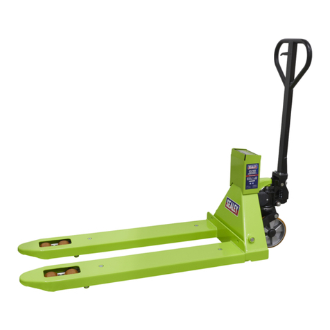
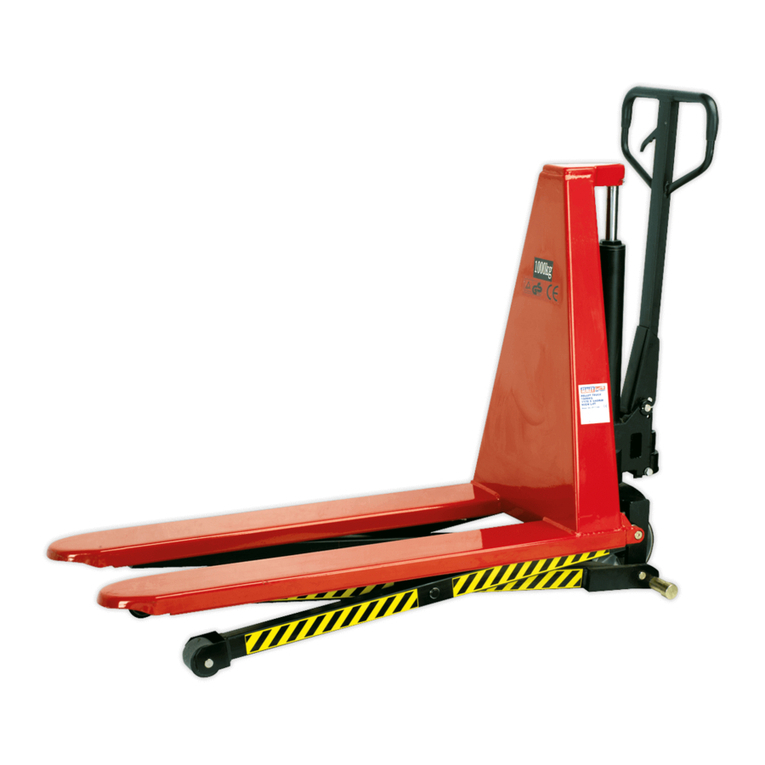
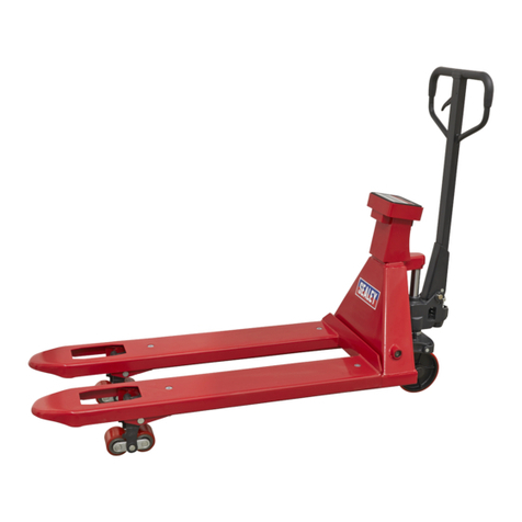
Heavy-duty pallet truck suitable for warehouse and general handling duties. Features built-in weighing scales with an accuracy of +/-1kg. Six-
digit, high contrast LCD display. Control panel has a Tare function to make an allowance for packaging weight. Scales powered by four AA
batteries allowing up to 70 hours of use. Automatic sleep mode ensures battery life is prolonged when not in use. Ergonomic handle for
comfortable operation.
Specification.
Model No ............................................................PT1150SC
Capacity . . . . . . . . . . . . . . . . . . . . . . . . . . . . . . . . . . . . . . . . . . . . . . . . . . . . . . . . . . . . . . . .2000kg
Power source ........................................................4 x AA cells
Environment ................................................. General purpose, dry
Operating temperature ..................................-10°C to 40°C (14°F to 104°F)
Min/Max fork height ....................................................88/200mm
Fork Spread ............................................................ 200mm
Width ................................................................. 555mm
Fork length .............................................................1150mm
Display ............................................................Six-digit LCD
Weighing Units ................................................. Pounds, Kilograms
fig.1
INSTRUCTIONS FOR:
2000KG PALLET TRUCK WITH SCALES
MODEL No: PT1150SC.V2
Original Language Version PT1150SC.V2 Issue:3(SP)-26/04/13
© Jack Sealey Limited
5.1. The operating handle control lever can be set to one of three positions, as shown in fig.4.
They are:
5.1.1. RAISE: Control lever in the DOWN position.
5.1.2. DRIVE: Control level in the CENTRAL position.
5.1.3. LOWER: Control lever in the UP position.
5.2. If the above positions have been altered, they can be restored by carrying out the
following adjustments.
5.2.1. If the forks rise whilst pumping in the DRIVE position, turn the adjusting nut (fig.2D)
on the adjusting bolt (fig.2E) or the screw (fig.3F) clockwise, until the pumping
action does not raise the forks and the DRIVE position functions normally.
5.2.2. If the forks lower whilst pumping in the DRIVE position, turn the adjusting nut (fig.2D)
or the screw (fig.3F) counterclockwise, until the pumping action does not lower the
forks.
5.2.3. If the forks do not lower when the control lever is in the LOWER position, turn the
adjusting nut (fig.2D) or the screw (fig.3F) clockwise, until raising the control lever
lowers the forks.
NOTE: Check the DRIVE position again by repeating paragraphs 5.2.1 and 5.2.2 to ensure
that the adjusting nut (fig.2D) and the screw (fig.3F) are still in the correct position.
5.2.4. If the forks do not rise when pumping in the RAISE position, turn the adjusting nut
(fig.2D) or the screw (fig.3F) counterclockwise until the forks rise.
NOTE: Check the LOWER and DRIVE positions again from paragraphs 5.2.1 to 5.2.3 to
ensure that the LOWER and DRIVE positions are functioning correctly.
5. OPERATING HANDLE ADJUSTMENT
fig. 3
fig.4
6. OPERATION
6.1. Operating the Pallet Truck
WARNING! An operator must be fully conversant with the safety instructions in Section 1.
6.1.1. Prior to operating the pallet truck, check the wheels, the operating handle and the fork unit to
ensure they are fit for purpose.
6.1.2. Move the truck with the operating handle control lever in the DRIVE position, as this makes the
operating handle easier to move and also depressurises the hydraulic pump. DO NOT overload
the pallet truck.
6.1.3. Ensure that the goods being transported are placed on the middle of the pallet truck forks. Refer
to fig.5. Depress the power ON switch on the right-hand side of the console.
6.2. Measuring Gross Weight
6.2.1. Set the operating handle control lever to the LOWER position and lower the pallet truck.
6.2.2. Place the pallet forks under the load to be weighed. Ensure that the load is correctly balanced.
Refer to fig.5.
6.2.3. Set the operating handle control lever to the RAISE position and pump the operating handle.
Ensure that the pallet is clear of the floor.
NOTE: The reading indicated on the console is the gross weight, i.e the weight of the goods and the
pallet.
6.3. Measuring Net Weight
NOTE: This method is used for goods packed on a standard pallet.
6.3.1. With an empty pallet on the forks, pump the operating handle with the control level in the RAISE
position until the pallet is clear of the ground, press the “TARE” key refer to fig.7. The console
will then display 0kg.
6.3.2. If you were to remove the pallet from the pallet truck forks. The console will then display minus
the weight of the pallet, (e.g. -20kg)
6.3.3. Add items to the pallet to see the weight then depress the "TARE" key (fig.7). Add another item
observe the weight and repeat until the pallet is full, press and hold the totalling key (fig.6) for 3
seconds to reveal the amount of items weighed and their combined weight excluding the pallet.
NOTE: To switch measurement between kilograms and pounds, depress the “FUNCTION” key (fig.8).
fig.5
fig.6
fig.7
fig.8
TOTALLING
KEY
TARE KEY
FUNCTION
KEY
4.1. Connect the operating handle to the hydraulic pump body using the pivot pin
(fig.2B) with a hole in the centre. Insert from left to right.
4.2. Align the pivot hole on the base of the handle with the pivot holes on the main
casting.
4.3. Insert the pivot shaft (using a soft hammer) insuring that the holes in either end of
the shaft (fig.2B) are aligned with the grooves on the outer sides of the main
casting (fig.2C).
4.4. When the shaft is properly aligned drive a roll pin through either end of the shaft.
4.5. Using thin nosed pliers, pass the end of the chain and with adjusting nut through
the hole in the centre of the pivot shaft.
4.6. Put the handle (fig.4) into its lowest position (RAISE).
4.7. Lift the actuating lever (fig.3E) against its spring pressure and slide the adjusting
bolt underneath so the chain (fig.2E) rests in between the forks.
fig. 2
4. OPERATING HANDLE ATTACHMENT
Original Language Version PT1150SC.V2 Issue:3(SP)-26/04/13
© Jack Sealey Limited
Problem Cause Solution
The forks cannot be raised to their maxi-
mum height,
- Their is insufcient oil in the reservoir. - Replenish the oil to the correct level.
The forks cannot be raised. - No hydraulic oil or impurities or air in the oil.
- The adjusting nut (g.2D) is too high keeping the
pumping valve open.
- Air has entered the hydraulic system.
- Replenish or change the oil.
- Reset the adjusting nut or bolt (g.2E).
- Purge the air from the hydraulic system.
The forks cannot be lowered - The piston rod (g.2A) or the pump is
deformed.
- Forks have been kept in the rise position
resulting in the rod jamming.
- The adjusting nut or bolt is incorrectly positioned.
- Replace the piston rod or pump.
- Keep the forks in the lowest position when
not in use.
- Adjust the nut or bolt.
The forks lower without the release valve
operating.
- Impurities, or air, has got into the release valve
oil.
- Parts of the hydraulic system have been
damaged.
- Adjusting nut (fig.2D) or bolt (fig.3F) incorrectly
positioned.
- Replace the oil and/or purge the air from
valve.
- Inspect and replace the damaged parts.
- Adjust the nut (fig.2D) or screw (fig.3F).
7.1. Daily Maintenance Check
7.1.1. Check the state of the wheels and the axles since thread, rags and other foreign objects can jam the wheels making safe, effective
operation difficult.
7.1.2. On completion of each task, unload the forks and return them to the lowest position.
7.2. Oil Check
7.2.1. Check the oil level at six monthly intervals. Sealey hydraulic jack oil is used with the pallet truck. The viscosity of the oil should be
30cSt at 40°C. The amount used in the pallet truck is approximately 0.4 litres.
7.3 Lubrication
7.3.1. The bearings and shafts of the pallet truck have long-life grease applied to them during manufacture. The bearings will only require
.greasing at monthly intervals or after the pallet truck had been serviced down to the lubrication points.
7.4. Purging Air from the Hydraulics
7.4.1. Air can get into the hydraulic oil through transportation, or the pump becoming misaligned. As a result, the forks will not elevate.
7.4.2. The air can be purged by setting the control level to the LOWER position and pumping the operating handle up and down for 30 - 40
seconds.
7.4.3. When the pallet truck is not in use, lower the forks and park the truck where it will not be a hazard.
8. TROUBLESHOOTING
8.1. Troubleshooting on the pallet truck.
8.2. Fault-finding on the weighing unit.
Problem Cause Solution
HELP1 on display - The load is too heavy for the scale. - Remove the load immediately
Scale is not accurate - The fork shoe is touching the bottom part of the
scale.
- Cable in junction box is loose.
- One of the load cells is broken.
- Remove anything that restricts movement
of the scale.
- Check the connection in the junction box
and conrm it is secure.
- Apply weight to all four corners of the
scale and the load cell with the different
weight should be replaced.
Display won't turn on. - Battery voltage is too low.
- Battery life is complete.
- Change the batteries.
7.5. Battery Replacement
7.5.1. To insert batteries, first remove the back cover at the rear of the console display unit.
7.5.2. Insert 4XAA cells making sure that they are correctly placed in the display unit.
7.5.3. Replace the cover on the display unit
NOTE: It is our policy to continually improve products and as such we reserve the right to alter data, specifications and component parts without prior notice.
IMPORTANT: No liability is accepted for incorrect use of this product.
WARRANTY: Guarantee is 12 months from purchase date, proof of which will be required for any claim.
INFORMATION: For a copy of our latest catalogue and promotions call us on 01284 757525 and leave your full name and address, including postcode.
01284 757500
01284 703534
sales@sealey.co.uk
Sole UK Distributor, Sealey Group,
Kempson Way, Suffolk Business Park,
Bury St. Edmunds, Suffolk,
IP32 7AR
www.sealey.co.uk
Web
email
7. MAINTENANCE
Original Language Version PT1150SC.V2 Issue:3(SP)-26/04/13
Parts support is available for this product. To obtain a parts listing and/or diagram, please log on to www.sealey.co.uk, email
sales@sealey.co.uk or phone 01284 757500.
© Jack Sealey Limited
Other Sealey Truck manuals

Sealey PT2500 User manual

Sealey

Sealey PT2500 User manual

Sealey CST806 User manual

Sealey

Sealey CST806 User manual

Sealey CST997.V2 User manual

Sealey

Sealey CST997.V2 User manual

Sealey CST989.V3 User manual

Sealey

Sealey CST989.V3 User manual

Sealey HPT1000 User manual

Sealey

Sealey HPT1000 User manual

Sealey PT1150LD User manual

Sealey

Sealey PT1150LD User manual

Sealey CST806 User manual

Sealey

Sealey CST806 User manual

Sealey PT2200.V2 User manual

Sealey

Sealey PT2200.V2 User manual

Sealey PT2200 User manual

Sealey

Sealey PT2200 User manual

Sealey PT1150SC.V4 User manual

Sealey

Sealey PT1150SC.V4 User manual

Sealey CST801 User manual

Sealey

Sealey CST801 User manual

Sealey CST985.V3 User manual

Sealey

Sealey CST985.V3 User manual

Sealey CST983.V2 User manual

Sealey

Sealey CST983.V2 User manual

Sealey DH01.V2 User manual

Sealey

Sealey DH01.V2 User manual

Sealey PT1150SC.V2 User manual

Sealey

Sealey PT1150SC.V2 User manual

Sealey CST991.V2 User manual

Sealey

Sealey CST991.V2 User manual

Sealey CST980.V2 User manual

Sealey

Sealey CST980.V2 User manual

Sealey CST800.V2 User manual

Sealey

Sealey CST800.V2 User manual

Sealey Premier CST990HD User manual

Sealey

Sealey Premier CST990HD User manual

Sealey Premier CST989HD User manual

Sealey

Sealey Premier CST989HD User manual

Sealey CST997.V2 User manual

Sealey

Sealey CST997.V2 User manual

Sealey PT1150SC.V3 User manual

Sealey

Sealey PT1150SC.V3 User manual

Sealey PT1150 User manual

Sealey

Sealey PT1150 User manual

Sealey Power Products HPT1000 User manual

Sealey

Sealey Power Products HPT1000 User manual

Popular Truck manuals by other brands

Scheppach DP4500 Translation of original instruction manual

Scheppach

Scheppach DP4500 Translation of original instruction manual

Komatsu HD465-7 brochure

Komatsu

Komatsu HD465-7 brochure

HERKULES AHW 2500 Original operating instructions

HERKULES

HERKULES AHW 2500 Original operating instructions

Kenworth SmartWheel KM816010 troubleshooting guide

Kenworth

Kenworth SmartWheel KM816010 troubleshooting guide

Mercedes-Benz 963 2022 Series manual

Mercedes-Benz

Mercedes-Benz 963 2022 Series manual

Mortuary Lift Stepper ERGO Operator's manual

Mortuary Lift

Mortuary Lift Stepper ERGO Operator's manual

Komatsu 930E-4 brochure

Komatsu

Komatsu 930E-4 brochure

Ravas 1100 manual

Ravas

Ravas 1100 manual

Mercedes-Benz Unimog BlueTec 6 Technical manual

Mercedes-Benz

Mercedes-Benz Unimog BlueTec 6 Technical manual

P.Lindberg 9050466 manual

P.Lindberg

P.Lindberg 9050466 manual

Clarke CPF300 Assembly instructions

Clarke

Clarke CPF300 Assembly instructions

Kimble Custom Chassis T00510 Safety manual

Kimble Custom Chassis

Kimble Custom Chassis T00510 Safety manual

Linde E25 Service training

Linde

Linde E25 Service training

Moxy MT 26 Shop Manual

Moxy

Moxy MT 26 Shop Manual

Noblelift PS E12B Service maintenance manual

Noblelift

Noblelift PS E12B Service maintenance manual

allen AT14S Operations & parts manual

allen

allen AT14S Operations & parts manual

Trail-Gear Duraline installation instructions

Trail-Gear

Trail-Gear Duraline installation instructions

jcb 505-20 Operator's manual

jcb

jcb 505-20 Operator's manual

manuals.online logo
manuals.online logoBrands
  • About & Mission
  • Contact us
  • Privacy Policy
  • Terms and Conditions
Copyright 2025 Manuals.Online. All Rights Reserved.