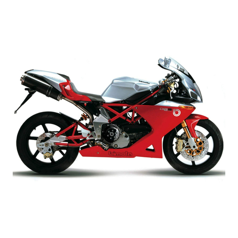
bimota DB7 Instruction manual


3
BIMOTA DB7
WORKSHOP MANUAL
2008, Bimota Spa.
All rights reserved.
The reproduction, in whole or part, of the topics covered in this
publication, is forbidden: all rights are reserved to Bimota to
which will require (written) authorization specifying the reasons.
Bimota

4
MANUAL PURPOSE – WARNINGS
This manual has been written by Bimota SpA primarily intended for use by dealers Bimota and their skilled
mechanics. Describes the service procedures for maintenance, repair and replacement of original parts of the
motorcycle in question. The technicians, that this manual is intended to, must have the adequate experience
and competence: some information has been deliberately omitted, because they have to be part of the indi-
spensable basics that a technician must have. The technicians in the use phase of the manual must comply
with the original technical specications given by the original manufacturer. Bimota assumes no responsibility
for errors or omissions of technical nature, produced in the writing of this manual. All the information provided
shall be updated at the time of printing, Bimota pursues a policy of continuous research and development, the-
refore, reserves the right to make changes of its products without prior notice and without obligation to make
the same changes to products already sold. The modications or signicant changes made to the specica-
tions or procedures will be reported to all Bimota authorized dealers and, where possible, will be included in
subsequent editions of this manual.
SIMBOLS
All indications right or left refer to the direction of travel of motorcycle.
Caution
The non-compliance with the instructions may create a situation of danger and cause serious personal injury
and even the death of the pilot, persons in the proximity, or person intent to repair the bike.
Important
Indicates the possibility of damage to the vehicle and/or its components if the instructions are not performed.
Notes
Provides useful information on the current operation.

5
USE OF THE MANUAL
This manual is an easy guide for technicians. All the procedures indicated in the manual are illustrated in a
detailed way and regards the operations of disassembly, assembly, inspection and repair.
The manual is divided in chapters. The name and the relative number, placed in a frame on the right upper1.
corner of each page, indicating the current chapter.
Each chapter is divided in sections. In the left upper part of each page is reported the title of the current2.
section, written in capital letters.
Paragraph title, written in small letters respect to the section title.3.
At the beginning of some sections, to make the procedures of disassembly more clear and to help the iden-4.
tication of the bike components, are reported the exploded drawings. It is possible to identify by number
the related piece.
The exploded drawing is accompanied by a list with the piece name and relative characteristics.5.
The instructions for the disassembly/assembly operations are described in sequence.6.
Some operations are accompanied by symbols with the purpose to supply more information and/or possi-7.
ble danger situation for the pilot or motorcycle.

Sez11-1
ENGINE 11
Summary
MANUAL PURPOSE – WARNINGS 4
SIMBOLS 4
USE OF THE MANUAL 5
11.1 - REMOVAL – REFITTING OF THE ENGINE ASSEMBLY SEZ11-4
Removal of the engine ............................................................................................................Sez11-5
Retting engine .......................................................................................................................Sez11-5
11.2 - LUBRICATION SYSTEM: OIL PUMP SEZ11-6
Removal of the oil pump .........................................................................................................Sez11-7
Disassembly of the oil pump ...................................................................................................Sez11-8
Reassembly of the oil pump ...................................................................................................Sez11-9
Retting the oil pump ..............................................................................................................Sez11-10
11.3 - LUBRICATION SYSTEM: OIL COOLER SEZ11-12
Removal of the lubrication system ..........................................................................................Sez11-13
Oil cooler inspection ................................................................................................................Sez11-14
11.4 - COOLING SYSTEM: WATER TANK SEZ11-15
Removal of the water tank .......................................................................................................Sez11-16
11.5 - WATER COOLING: WATER COOLER SEZ11-17
Disassembly water cooler .......................................................................................................Sez11-18
Water cooler inspection ..........................................................................................................Sez11-19
Renewal of the cooling fan ......................................................................................................Sez11-20
Removal of the cooling system hoses and unions ..................................................................Sez11-21
11.6 - COOLING SYSTEM: WATER PUMP SEZ11-25
Removal of the water pump ...................................................................................................Sez11-26
Retting the water pump .........................................................................................................Sez11-29
11.7 - CYLINDER HEAD ASSEMBLIES: CHECKS AND ADJUSTMENTS SEZ11-34
Checking and adjusting the valve clearances .........................................................................Sez11-35
Checking the closing clearance ..............................................................................................Sez11-36
Checking valve lift ...................................................................................................................Sez11-37
Checking the engine timing .....................................................................................................Sez11-39
11.8 - CYLINDER HEAD ASSEMBLIES: TIMING SEZ11-42
Removal of the timing belt covers ..........................................................................................Sez11-43
Removal of the tensioner pulley / timing belt ..........................................................................Sez11-44
Removal of the camshaft pulleys/idler pulley ..........................................................................Sez11-45
Removal of the tensioner and idler pulley mounting studs ......................................................Sez11-46
Disassembly of the camshaft pulleys ......................................................................................Sez11-46
Removal of the timing belt driveshaft pulleys ..........................................................................Sez11-47
Retting the timing belt driveshaft rollers ................................................................................Sez11-49
Retting the idler and tensioner pulley mounting studs ...........................................................Sez11-51
Reassembly of the timing pulleys ............................................................................................Sez11-52
Rimontaggio puleggie testa / tenditori ssi ..............................................................................Sez11-53
Retting the timing belts ..........................................................................................................Sez11-55
Retting the timing covers .......................................................................................................Sez11-58
11.9 - CYLINDER HEAD ASSEMBLIES: CAMSHAFTS SEZ11-59
Removal of the camshafts .......................................................................................................Sez11-60

Sez11-2
ENGINE 11
* Click on the desired item to go to the related section.
Checking the camshafts and supports ....................................................................................Sez11-62
Retting the camshafts ............................................................................................................Sez11-64
Oil seals ...................................................................................................................................Sez11-67
Rocker cover ...........................................................................................................................Sez11-68
Removal of the intake manifold and coolant union ..................................................................Sez11-71
11.10 - CYLINDER HEAD ASSEMBLIES: VALVES - ROCKER ARMS SEZ11-72
Removal of the cylinder heads ................................................................................................Sez11-73
Removal of the valves .............................................................................................................Sez11-74
Removing the valve rocker arms .............................................................................................Sez11-75
Overhaul of cylinder head components ...................................................................................Sez11-79
Valve seat ................................................................................................................................Sez11-80
Valve guides ............................................................................................................................Sez11-82
Checking the valve ..................................................................................................................Sez11-84
Checking the valve seal ..........................................................................................................Sez11-86
Checking the rocker arms .......................................................................................................Sez11-86
Opening and closing shims - Springs ......................................................................................Sez11-87
Reassembly of the cylinder head ............................................................................................Sez11-87
Valve guide seals ....................................................................................................................Sez11-88
Reassembly of the closing rocker arms. .................................................................................Sez11-88
Retting the valves, closing shims and half rings ....................................................................Sez11-91
Retting the opening shims and opening rocker arms ............................................................Sez11-93
Fitting the cylinder head assemblies .......................................................................................Sez11-96
11.11 - CYLINDER / PISTON ASSEMBLIES SEZ11-98
Removal of the cylinder/piston assembly ................................................................................Sez11-99
Overhaul of the cylinder barrel/piston components .................................................................Sez11-103
Checking the piston-cylinder clearance ...................................................................................Sez11-104
Checking the piston ring-grooves clearance ...........................................................................Sez11-106
Checking the piston ring/cylinder clearance ............................................................................Sez11-107
11.12 - CLUTCH ASSEMBLY: CLUTCH SEZ11-108
Description ..............................................................................................................................Sez11-109
Removal of the clutch ..............................................................................................................Sez11-110
Inspection and overhaul of the clutch components .................................................................Sez11-115
11.13 - CLUTCH ASSEMBLY: RIGHT-HAND SIDE CRANKCASE COVER SEZ11-117
Removal of the right-hand side crankcase cover ....................................................................Sez11-118
11.14 - CLUTCH ASSEMBLY: PRIMARY DRIVE GEARS SEZ11-121
Removal of the primary drive gears ........................................................................................Sez11-122
Retting the primary drive gears and checking backlash ........................................................Sez11-125
11.15 - GEARBOX ASSEMBLY: GEARCHANGE MECHANISM SEZ11-128
Removal of the gearchange mechanism .................................................................................Sez11-129
Disassembly of gear interlock plunger and pawl assembly .....................................................Sez11-131
11.16 - GEARBOX ASSEMBLY: GEARBOX SHAFTS SEZ11-132
Removal of the gearbox assembly ..........................................................................................Sez11-133
Disassembly of the gearbox shafts .........................................................................................Sez11-135
Disassembly of the gearbox output shaft ................................................................................Sez11-135
Disassembly of the gearbox input shaft ..................................................................................Sez11-138
Overhaul of the gearbox ..........................................................................................................Sez11-141
Inspection of the gear selector forks .......................................................................................Sez11-142
Inspection of the gear selector drum .......................................................................................Sez11-143

Sez11-3
ENGINE 11
* Click on the desired item to go to the related section.
11.17 - FLYWHEEL-ALTERNATOR SEZ11-144
Removal of the left-hand side crankcase cover ......................................................................Sez11-145
Disassembly of the left-hand crankcase cover ........................................................................Sez11-147
Removal of the ywheel/alternator assembly ..........................................................................Sez11-149
Overhaul of the ywheel/alternator assembly .........................................................................Sez11-150
Disassembly of the ywheel/alternator ....................................................................................Sez11-151
Reassembly of the ywheel-alternator assembly ....................................................................Sez11-152
11.18 - CRANKCASE ASSEMBLY: EXTERNAL COMPONENTS SEZ11-157
Removal of external components ............................................................................................Sez11-158
Retting the external components ...........................................................................................Sez11-161
Removal of the timing gears ....................................................................................................Sez11-166
Removal of the starter motor idler gear ...................................................................................Sez11-167
Checking the engine sensor air gap ........................................................................................Sez11-168
11.19 - CRANKCASE ASSEMBLY: CRANKCASE HALVES SEZ11-170
Separation of the crankcase halves ........................................................................................Sez11-171
Overhaul of the crankcase halves ...........................................................................................Sez11-174
Main bearings ..........................................................................................................................Sez11-178
Shimming the shafts ................................................................................................................Sez11-179
Shimming the crankshaft .........................................................................................................Sez11-180
Shimming the gearbox shafts ..................................................................................................Sez11-183
Shimming the gearbox selector drum ......................................................................................Sez11-184
11.20 - CRANKCASE ASSEMBLY: CONNECTING RODS SEZ11-185
Removal of the connecting rods assembly ..............................................................................Sez11-186
Disassembly of the connecting rods ........................................................................................Sez11-186
Overhaul of the connecting rods .............................................................................................Sez11-187
Renewal of the small end bushing ..........................................................................................Sez11-188
Connecting rod bearings .........................................................................................................Sez11-188
Crankshaft ...............................................................................................................................Sez11-189
Big-end bearing shell-journal clearance ..................................................................................Sez11-192
Reassembly of the connecting rods ........................................................................................Sez11-192
Retting the connecting rods. ..................................................................................................Sez11-195

Sez11-4
ENGINE 11
11.1 - REMOVAL – REFITTING OF THE ENGINE ASSEMBLY
1) Engine spindle
2) Nut M12x1,25
3) Spacer

Sez11-5
Removal of the engine
In order to remove engine you must rst remove a series of other components from the motorcycle.
Most of these removal procedures are described in the relative sections of this manual.
This section describes only the operations to be carried out after having removed all the parts listed belowe:
- Tail, Fuel tank, side fairing, front fairing
- Throttle control, airbox, throttle body, exhaust system
- Foot lever gearshift assembly, rear brake pump, Clutch piston assembly, engine driving pinion
- Engine wiring, battery box mount, oil cooler and pipes, cooling system
- Swingarm, swingarm plate dx-sx, shock absorber rocker
Place a stand beneath the engine to support it during removal from the frame.
Loosen the two spindle nuts (2) on the left or the right side.
Take the spindles (1) off. In this moment the engine unit is detached by the frame.
Take the engine off from the frame pulling it down and forward.
Retting engine
To reassemble repeat the assembling operation in reverse order.
Important
Add grease under the nuts (2) and tighten to specied torque.
ENGINE 11

Sez11-6
ENGINE 11
1) Complete oil pump assembly
2) O-ring
3) Circlip
4) O-ring
5) Pump body
6) Circlip
7) Reducer bush
8) Spring washer
9) Bolt
10) Bolt
11) Spring washer
12) Pump drive gear
13) Key
14) By-pass plug
15) Locating dowel
16) By-pass spring
17) By-pass valve
11.2 - LUBRICATION SYSTEM: OIL PUMP

Sez11-7
ENGINE 11
Removal of the oil pump
Drain the oil from the lubrication system
Remove the engine from the frame
Remove the right-hand side crankcase cover
Undo and remove the bolts (9) and (10) securing the pump assembly.
Remove the oil pump assembly (1) and extract O-rings (2) and (4) from the crankcase half together with two
centring bushes (15).

Sez11-8
ENGINE
Disassembly of the oil pump
Hold the oil pump (1) in a vice taking care not to damage the drive gear (12).
Warning
Make sure that vice jaws are faced with soft material.
Remove the plug (14) and extract the spring (16) and by-pass valve (17).
Check the condition of the above components.
Remove the circlip (6) and withdraw the pump drive gear (12).
11

Sez11-9
ENGINE
Reassembly of the oil pump
Check that the circlip (3) and Woodruff key (13) are both present on the pump.
Fit the pump drive gear (12) on to the oil pump and secure it by installing the circlip (6) in its groove.
Install in the pump the by-pass valve (17) and the spring (16); screw in the plug (14) and tighten to the specied
torque, after applying a medium strength threadlocker.
11

Sez11-10
ENGINE
Retting the oil pump
Position the locating dowels (15) and the O-rings (2) and (4) in correspondence with the crankcase lubrication
oilways.
Position the oil pump on the crankcase and tighten the bolts (9) and (10) to the specied torque.
Check the gear backlash with the driving pinion by xing dial gauge part no. 88765.1518, equipped with the
relevant stylus, to the crankcase.
Set dial gauge stylus on one tooth of oil pump gear and zero set instrument in this position.
Move gear slightly to measure play; take four readings in diametrically opposed positions of the gear.
The backlash should be 0.10 mm.
11

Sez11-11
ENGINE
Ret the right-hand crankcase cover
Ret the engine to the frame
Fill the lubrication system with oil
11

Sez11-12
ENGINE
11.3 - LUBRICATION SYSTEM: OIL COOLER
1) Bolt M6x25 TCEI CZ
2) Gasket 6x18x1.6
3) Rubber mounting
4) Aluminium gasket sp.2
5) Nipple
6) Gasket
7) Oil hose
8) Support
9) Nut M6
10) Spacer
11) Oil cooler
12) Bolt M6X12 TE
13) Gasket
14) Oil hose
11

Sez11-13
ENGINE
Removal of the lubrication system
Remove the side fairings
Drain the oil from the lubrication system
Undo the nuts (A) on the feed and return hoses (7) - (14) and the nipples (5) and disconnect them from the
engine.
Unscrew the nipples (5) on the crankcase and recover the gaskets.
During removal, take care not to lose the O-rings (1) which ensure a tight seal.
11

Sez11-14
ENGINE
Unscrew and remove the bolt (14) - (5) securing the oil cooler to the support (8).
The support (8) can now be removed by unscrewing the bolts (12).
Unscrew the feed and return hoses (7) - (14) from the oil cooler (1).
Oil cooler inspection
Make a visual inspection of the oil cooler. Renew the cooler in the presence of damage or leaks.
11

Sez11-15
ENGINE
11.4 - COOLING SYSTEM: WATER TANK
1) Water tank
2) Tank cap
3) ECU mounting plate
4) Screw M5x10 TBEI
5) Water return hose
6) Water delivery hose
7) H. cylinder hose
8) V. cylinder hose
9) Clamp
10) Hose
11) Clamp
12) Clamp
13) Thermostat
14) Hose guide clamp
15) Clamp
16) Water temperature sensor
17) Screwed bush
18) Clamp
19) Sensor
20) O-Ring
21) Water outlet union (horizontal)
22) Water outlet union (vertical)
23) Plate
24) Screw
11
Other manuals for DB7
1
Table of contents
Other bimota Motorcycle manuals
